HAL Id: pastel-00564365
https://pastel.archives-ouvertes.fr/pastel-00564365
Submitted on 8 Feb 2011HAL is a multi-disciplinary open access archive for the deposit and dissemination of sci-entific research documents, whether they are pub-lished or not. The documents may come from teaching and research institutions in France or abroad, or from public or private research centers.
L’archive ouverte pluridisciplinaire HAL, est destinée au dépôt et à la diffusion de documents scientifiques de niveau recherche, publiés ou non, émanant des établissements d’enseignement et de recherche français ou étrangers, des laboratoires publics ou privés.
NiTi/ époxyde : effets de la transformation
martensitique sur le comportement mécanique et sur la
décohésion interfaciale
Yousef Payandeh
To cite this version:
Yousef Payandeh. Elaboration et caractérisation de composites intelligents NiTi/ époxyde : effets de la transformation martensitique sur le comportement mécanique et sur la décohésion interfaciale. Mécanique des matériaux [physics.class-ph]. Arts et Métiers ParisTech, 2010. Français. �NNT : 2010ENAM0032�. �pastel-00564365�
Arts et Métiers ParisTech - Centre de Metz Laboratoire de Physique et Mécanique des Matériaux
2010-ENAM-0032
École doctorale n° 432 : Science des Matériaux de l’Ingénieur
présentée et soutenue publiquement par
Yousef PAYANDEH
le 14 décembre 2010
Elaboration et caractérisation de composites intelligents NiTi/
époxyde
Effets de la transformation martensitique sur le comportement
mécanique et sur la décohésion interfaciale
Doctorat ParisTech
T H È S E
pour obtenir le grade de docteur délivré par
l’École Nationale Supérieure d'Arts et Métiers
Spécialité “ Mécanique et Matériaux ”
Directeur de thèse : Fodil MERAGHNI Co- directeur de thèse : Etienne PATOOR
T
H
È
S
E
Jury :Mme Shabnam ARBAB CHIRANI Maitre de conférences HDR, LBMS, ENIB- Brest Rapporteur M. Joris DECRIECK Professeur, Université de Gent, Belgique, Rapporteur
M. Frédéric JACQUEMIN Professeur, Université de Nantes Examinateur
M. André EBERHARDT Professeur Examinateur
M. Fodil MERAGHNI Professeur, LPMM, ENSAM, Metz Examinateur M. Etienne PATOOR Professeur, LPMM, ENSAM, Metz Examinateur
In this work a near equiatomic NiTi shape memory wire epoxy matrix composite is studied. The NiTi wire in as drawn condition was subjected to three heat treatments in order to prepare the wires with different transformation characteristics. Three metallic moulds were designed for different types of samples, namely pull-out, tensile and heterogeneous test specimens. The composite specimens were elaborated by casting followed by curing and post curing process. The tests were conducted at three temperatures (20, 80 and 90 °C) and at a constant cross-head speed.
The single NiTi wire specimens with a long embedded length were subjected to the pull-out test in order to study the effect of martensitic transformation/reorientation on the debonding initiation and also on the debonding propagation. For comparison, several steel wire samples were prepared through the same procedure. From in-situ observations, the debonding begins from wire entry point and proceeds to the embedded end. It was observed that when no phase transformation occurs in the wire, the debonding propagates rapidly whilst it is slow when there is wire phase transformation or martensitic reorientation. It was found that the debonding rate depends on the displacement rate as well as the length change during phase transformation. It has been experimentally found that, the interfacial shear strength increases when the martensitic transformation takes place.
The mechanical behavior of the resin matrix and the effect of test temperature, wire volume fraction have been determined using standard tensile test. The tests have been conduced at three temperatures. It is found that the martensitic transformation occurring in the wire affect the mechanical behavior of the composite specimens. In this way, using the wire with larger transformation stress enhances the composite tensile strength. This is achieved either by increasing the test temperature or by using the wires heat treated at lower temperatures. It is proposed that on the constraint of matrix, the transformation occurs simultaneously at several points that result in intermittent debonded and bonded zones.
In this work the samples with complex geometry were designed and fabricated in order to estimate the elastic properties of the composite material in two directions (perpendicular and parallel to the wire axis). The specimens with random speckle were then subjected to the simple loading. The heterogeneous displacement/strain fields generated due to the complex geometry of the composite samples were measured. An inverse method was established in this work and the material parameters were identified. The results were then compared to the results obtained by Mori-Tanaka method. Moreover, the numerical strain fields obtained using the identification parameters was compared to the experimental ones. A good correlation was found in both cases.
ii
My parents
my wife
and
i I am deeply grateful to my supervisors Fodil Meraghni, Etienne Patoor and André Eberhardt for their scientific ideas and help during my five years in “Arts et Metiers ParisTech”. I also wish to thank them for their kind and encouragements. I would like to express my gratitude to Professor Joris Degrieck, Shabnam Arbab Shirani and Frederic Jaquemin for accepting to be on my thesis committee.
I would like to thank all my colleagues who helped me during this work, Bagher, Abderrahim, Nadine, Laurent, Oussama, Hedi, Rachid, Célia, Stephan, Alain, Gael, Olivier, Daniel, Marc and Badis.
Although a 5000-Km distance separates me from my parents, family and friends in Iran, please be assured that you are very close in my heart! I am grateful to all my friends for helping me from this long distance, in particular Hossein, Abbas, Mehrdad, and Hassan.
I am thankful to Ali Siadat and Fathallah Qods for advises and helps during my life in Metz. I wish to thank Bagher, Behrooz, Esmaeil, Somayeh, Hojat, Sahar, Shahab, Mohammad, Amir, Hossein and Vahid for their kind.
iii
Part I: Thesis
Table of figures ... viii
List of tables ... xiii
Introduction ... 1
Chapter 1. shape memory alloys and smart composites
4
1.1. Description of Shape Memory Alloys ... 4
1.1.1. General Properties ... 4
1.1.1.1. Introduction... 4
1.1.1.2. Martensitic phase transformation ... 5
1.1.1.3. Shape memory effect (SME) ... 7
1.1.1.4. Superelasticity (SE) ... 8
1.1.2. Martensitic transformation in NiTi based alloys ... 12
1.2. State of the art of SMA composites ... 14
1.2.1. SMA-Polymer composite ... 15
1.2.1.1. NiTi-Epoxy matrix composite ... 17
1.2.1.2. Interfacial properties ... 19
1.2.2. SMA/metal matrix composites ... 19
1.2.3.1. Al matrix ... 20
1.2.3.2. Sn / In matrix ... 20
1.3. Identification techniques and Digital Image Correlation ... 21
1.3.1. Techniques d‟identification ... 21
1.3.1.1. Introduction... 21
1.3.1.2. Méthode de recalage par éléments finis ... 22
1.3.1.3. Méthode de l‟erreur en relation de comportement ... 23
1.3.1.4. Méthode de l‟écart à l‟équilibre ... 24
1.3.1.5. Méthode des champs virtuels ... 25
1.3.2. Techniques de mesure de champs cinématiques ... 26
1.3.2.1. Généralités ... 26
1.3.2.2. Techniques de corrélation d‟images numériques ... 28
1.3.2.2.1. Logiciel de corrélation d‟images numériques Correli LMT et Q4 ... 33
Algorithme de calcul et traitement numérique ... 33
Les particularités du logiciel Correli Q4 ... 34
Performances sur les déplacements et les déformations ... 36
1.3.2.2.2. Logiciel de corrélation d‟images numériques Vic2D ... 39
iv
2.1. Objectives ... 57
2.2. Materials description ... 57
2.2.1. SMA wire ... 59 2.2.2. Epoxy matrix ... 662.3. Sample preparation ... 72
2.4. Pull-out test ... 74
2.5. Uniaxial tensile test ... 76
2.6. Heterogeneous test ... 77
References ... 80
Chapter 3. Characterization of the matrix/wire interface- influence of the
martensitic transformation
83
3.1. Introduction ... 83
3.2. Analytical method ... 84
3.3. Effect of martensitic transformation on debonding initiation ... 88
3.4. Effect of martensitic transformation on debonding propagation ... 93
3.5. Conclusion ... 97
References ... 99
Chapter 4. Tensile properties: characterization and micromechanical
modeling- influence of the martensitic transformation
102
4. 1. Introduction ... 102
4. 2. Experimental results ... 104
4. 3. Micromechanical analysis ... 111
4.3.1. Model development ... 111 4.3.2. Numerical results ... 1174.4. Discussion ... 119
4.4.1. Comparison of micromechanical and experimental results ... 119
4.4.2. Effect of martensitic transformation on the mechanical behavior ... 127
4.4.3. Effect of martensitic transformation on the debonding mechanism ... 129
4.5. Conclusion ... 134
v
5.1. Introduction ... 139
5.2. Inverse Method ... 140
Identification algorithm ... 140 Cost function ... 140 Optimization algorithms ... 141 a- Gauss-Newton method ... 141 b- Levenberg-Marquardt ... 143Determination of the sensitivity matrix ... 144
Stop criteria ... 145
5.3. Application to the NiTi wire composite ... 145
5.3.1. Convergence and stability analysis ... 148
5.3.1.1. Convergence test ... 148
Influence of the experimental database ... 148
Influence of the number of element and mesh size ... 149
Influence of the initial estimation ... 151
Influence of the regularization parameter (μ) ... 153
5.3.1.2. Stability analysis ... 154
5.4. Application for experimental strain fields ... 155
Correli-Q4 software ... 155
Vic2D software ... 156
5.4. Identification results ... 157
5.4.1. Identification results using Correli-Q4 ... 157
4.4.2. Identification results using Vic2D ... 159
5.5. Conclusion ... 164
References ... 165
Conclusion
169
Appendix A: Mechanical behavior of the composite samples
172
A.1. Experimental results ... 172
vi
Part II: Résumé étendu
Résumé étendu
180
Résumé ... 180
1. Introduction ... 182
2. Processus de fabrication et méthodologie de caractérisation ... 183
3. Caractérisation de l'interface matrice/ fils - Influence de la transformation
martensitique ... 189
4. Propriétés en traction : caractérisation et modélisation micromécanique,
influence de la transformation martensitique ... 197
5. Identification des paramètres ... 204
6. Conclusion ... 210
vii Chapter 1
Fig. 1.1. Free energy changes during martensitic phase transformation
Fig. 1.2. Schematic representation of the SME. The SMA material is deformed (AB) and unloaded (BC) at a temperature below Mf (MMf). The resulting deformation is restored during heating to a
temperature above Af (CD). The original dimensions are re-gained (DA) [Parlinska et al. 2001]. Fig. 1.3. Isothermal and isobaric pseudoelastic loading paths. The two most commonly encountered pseudoelasticity loading paths - and isothermal and isobaric one. For clarity, the initial loading from austenite to achieve the required constant stress for the isobaric path is not shown [Patoor et al. 2006]. Fig. 1.4. Schematic of isothermal, pseudoelastic stress-strain curve. The critical stresses σMs, σMf, σAs and σAf
required for initiation and completion of the forward and reverse transformation are obtained from the phase diagram on Figure 3. The maximum uniaxial transformation strain Ht is also shown [After Patoor et al. 2006].
Fig. 1.5. Schematic of isobaric, cooling/heating cycle. The critical temperatures Mσs , Mσf , Aσs and Aσf required for initiation and completion of the forward and reverse transformation are obtained from the phase diagram on Figure 3. [After Patoor et al. 2006].
Fig. 1.6. Typical Stress-Strain-Temperature curves for the Shape Memory alloys [Bernal 2004]. Fig. 1.7. Schematic representation for the appearance of shape memory effect and superelasticity, which is termed as „„Transformation Pseudoelasticity‟‟ here, in temperature–stress space [Otsuka and Shimizu 1986].
Fig. 1.8. Three transformation paths in Ti–Ni-based alloys [Otsuka and Ren 2005]
Fig. 1.9. Stress–strain curves as a function of temperature of a Ti–50.5Ni single crystal, which was aged at 673 K for 1 h after solution-treatment. The S–S curves are related with R-phase transformation or deformation of R-phase. T„R= Rs [Miyazaki et al. 1988].
Fig. 1.10: Schématisation des termes métrologiques de résolution, incertitude et limite de détection [Triconnet 2007].
Figure 1.11: Schéma d‟un montage de corrélation d‟images numériques bidimensionnel, [Sutton et al. 1999].
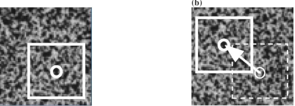
Figure 1.12 : Exemple pour un déplacement de corps rigide du mouchetis (a) image et imagette de référence et (b) image et imagette déformée à l‟instant t.
Fig. 1.13 : Principe de la technique de corrélation d‟images numériques avec Correli Q4 [El Bartali 2007]
viii
Fig. 2.1. DSC for M-550 and M450 with 5 K/min in Ar and M-400 wires with 10 K/min in He atmosphere
Fig. 2.2. Stress -Strain diagram for a) M-400, b) M-450 and c) M-550 wires at room temperature Fig. 2.3. Stress -Strain diagram for a) M-400, b) M-450 and c) M-550 wires at 80 °C
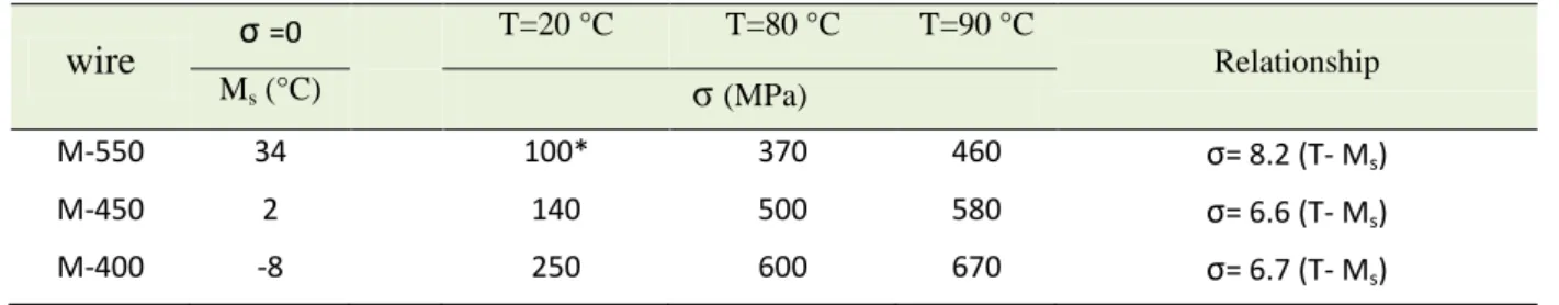
Fig. 2.4.Stress --Strain diagram for a) M-400, b) M-450 and c) M-550 wires at 90 °C Fig. 2.5. Variation of Ms under stress for all three wires
Fig.2.6. DSC results for TR3, TR4 and TR5, 10 K/min in air atmosphere Fig. 2.7. Mechanical behavior of epoxy matrix at room temperature.
Fig. 2.8. Mechanical behavior of the epoxy matrix at different temperatures (TR4).
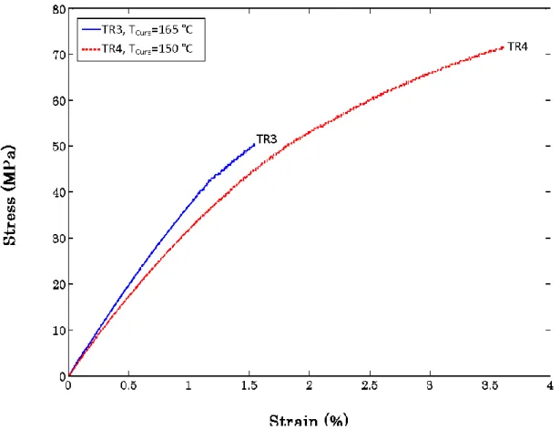
Fig. 2.9. Mechanical behavior of the epoxy matrix for two post curing temperatures (TR3 and TR4). Fig.2.10. The mould for pull-out specimensFig. 2.11. The mould using to prepare the simple tensile samples and the specimens with complex geometry
Fig. 2.12. Macroscopic cracks existing in the samples fabricated with a brittle matrix
Fig.2.13. Residual thermal stress for a M-550 NiTi wire epoxy matrix composite using photoelastisity Fig.2.14. Experimental set-up
Fig.2.15 (a) Experimental set-up (b) side section (c) up view Fig. 2.16. The simple tensile test specimen
Fig. 2.17. Heterogeneous strain fields generated in Meuwissen-type sample, applied displacement: 0.6 mm
Fig. 2.18. The Heterogeneous test specimen
Fig. 2.19. The experimental set-up with a Meuwissen sample. View of the random speckle pattern.
Chapter 3
Fig. 3.1- Maximum shear stress vs. applied stress, τi and σp *
are interfacial shear strength and debonding stress, respectively
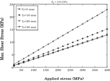
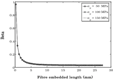
Fig. 3.2. Maximum shear stress vs. applied stress for different embedded wire lengths Fig3.3- Beta vs. embedded wire length for different applied stresses
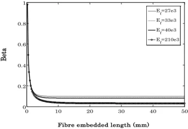
Fig. 3.4- Beta vs. embedded wire length for different specimen diameters Fig. 3.5- Beta vs. embedded wire length for different wire‟s Young moduli Fig3.6- Beta vs. embedded wire length for different wire radius
ix
the first case the last one was taken just after completed debonding. The arrows show the position of debonding.
Fig. 3.8- Force - Displacement diagram for the specimens with (a) M-550 and (b) M450 wire Fig. 3.9- Force - Displacement diagram for the specimens with M-400 wire (a) without and (b) with transformation
Fig. 3.10 - Force - Displacement diagram for the specimens with steel wire Fig. 3.11- Maximum shear stress vs. applied stress for different wire‟s Young moduli
Fig. 3.12- Debonding rate for a specimen with a) M-550, b) M-400 and c) M-400 wires d) a, b and c for comparisonFig. 3.13- Normalized force and debonding rate for the specimen of Fig. 3.9-b and 3.12-c,the force is divided by transformational load and the DR is divided by the average rate.
Chapter 4
Fig. 4.1- Stress -Strain diagram for the composite samples with M450 wire, at 80 °C and with vf=0.06. Fig. 4.2- Stress -Strain diagram for the composite samples with M550 wire, at 80 °C and with vf=0.06. Fig. 4.3- Stress -Strain diagram for the composite samples with M550 wire, at 80 °C and with vf=0.12. Fig. 4.4. Stress -Strain diagram for the composite samples with M550 wire at 80 °C for different wire volume fractions.
Fig. 4.5. Stress -Strain diagram for the composite samples with M550 wire with Vf=0.06, at different temperatures.
Fig. 4.6. Stress -Strain diagram for the composite samples with M550 wire with vf=0.12, at different temperatures.
Fig. 4.7. Stress -Strain diagram for the composite samples with vf=0.06 at 80 °C for two different wires.
Fig. 4.8. Stress -Strain diagram for the composite samples with vf =0.12 at 90 °C for three different wires.
Fig. 4-9. Axial and shear stress distribution along an embedded wireFig. 4-10. Axial and shear stress distribution along an embedded wire
Fig. 4-10. Axial and shear stress distribution along an embedded wire Fig. 4-11. Stress-strain behavior of the matrix, wire and composite at 20 °C
Fig. 4.12. Stress -Strain diagram for the composite samples with different wires at 20°C for Vf=0.12. Fig. 4.13- Stress -Strain diagram of composite samples with M550 wire vf=0.12 at three temperatures. Fig. 4.14- Stress -Strain diagram for the composite samples with M550 wire at 90°C for three Vf. Fig. 4.15. Mechanical behavior of the M550 wire composite for Vf=0.06 at 80 °C
x
Fig. 4.17. Mechanical behavior of the M550 wire composite for Vf=0.12 at 80 °C Fig. 4.18. Mechanical behavior of the M550 wire composite for Vf=0.06 at 90 °C Fig. 4.19. Mechanical behavior of the M450 wire composite for Vf=0.06 at 80 °C Fig. 4.20. Mechanical behavior of the M450 wire composite for Vf=0.12 at 90 °C Fig. 4.21. Mechanical behavior of the M400 wire composite for Vf=0.12 at 90 °C Fig. 4.22. Young modulus vs. temperature for three volume fractions
Fig. 4.23. Young modulus vs. volume fraction for three temperatures Fig. 4.24. Tensile strength vs. temperature for three volume fractions Fig. 4.25. Tensile strength vs. volume fraction for three temperatures Fig. 4.22. Tensile strength for samples with three wires (Vf=0.12 ) at 90 °C
Fig. 4.27. Normalized debonded length (Ld) vs. applied strain for different wires at 20 °C. Fig. 4.28. Normalized debonded length (Ld) in 0. 5% applied strain for different wires at 20 °C. Fig. 4.29. Normalized debonded length (Ld) in 0. 5% applied strain for NiTi wires vs. temperature. Fig. 4.30. Applied strain at which the debonding begins vs. temperature for NiTi wire samples Fig. 4.31- Interfacial shear stress vs. length for steel wire in three strain levels.
Fig. 4.32- Interfacial shear stress vs. length for M550 wire in three strain levels.
Fig. 4.33- Stress -Strain diagram for the composite samples with M450 and M550 wires, at 80 °C. Fig. 4-33. The debonded regions taking place in NiTi wire composites
Fig. 4.34- longitudinal stress distribution for M550 wire composite samples in four strain levels (at 20°C, Vf=0.06).
Fig. 4.35. Stress distribution in the embedded M550 wire with martensitic reorientation at T=20 °C Fig. 4.36. Stress distribution in embedded steel wires (without MT) at 20 °C
Fig. 4.37. Stress distribution in embedded M450 wires with MT at 20 °C
Chapter 5
Fig. 5.1. Identification method
Fig. 5.2. Calculation of sensitivity matrix for n parameters Fig. 5.3. Effect of mesh size on the reaction force
Fig. 5.4. The zones of interest (ZOI) with a) 656, b) 400, c) 336 elements
xi
Fig. 5.7. Variation of a) the cost function and b) the parameters versus iteration number.
Fig. 5.8. Variation of a) the cost function and b) the parameters versus iteration number for 5% error. Fig. 5.9. Variation of a) the cost function and b) the parameters versus iteration number for 10% error. Fig. 5.10- The element size and the sub-image location in a) FE and b) experimental studied areas Fig.5.11- Strain ε22 calculated numerically in each element using the identified parameters compared to the experimental values
Fig.5.12- Strain ε11 calculated numerically in each element using the identified parameters compared to the experimental values
Fig.5.13- Strain ε12 calculated numerically in each element using the identified parameters compared to the experimental values
Fig. 5.14. Strain fields determined experimentally using VIC2D are compared to the numerical ones Fig. 5.15. Displacement fields determined experimentally using VIC2D are compared to the numerical ones
Fig. 5.16. Identification results compared to the results obtained from tensile test
Fig. 5.17. Identification results compared to the results calculated by Marfia and Sacco [25] Fig. 5.18. Identification results compared to the results obtained using Mori-Tanaka‟s model
xii Chapter 2
Table 2.1. Some characteristics of NiTi wires subjected to different heat treatments Table 2.2. Transformation temperatures (°C) of NiTi alloys after selected heat treatments Table 2.3- The stress at which the transformation begins in the wires
Table 2.4. The preparation and curing conditions and obtained glass transition temperatures (Tg ° C)
Chapter 3
Table 3.1. Variation of the parameters in the model of Fu [2] for different wire lengths and Young‟s moduli using a = 0.5 mm, b = 7.5 mm, σp = 100 MPa
Table 3.2. The calculated model dimensionless constants for different wire lengths and Young‟s moduli using a = 0.5 mm, b = 7.5 mm
Table 3.3. Results summary
Table 3.4- Debonding rate, vd, displacement rate Vi (mm/min) and ε tr
and their relationship
Chapter 4
Table 4.1. Young modulus and stress at 2% strain for M550 wire composites at different temperatures Table 4. 2. Stress at 2% strain for composites with different wires at 90 °C
Table 4. 3. Change of trend in stress-strain curve at different temperature for M550 wire samples Table 4. 4. Change of trend in stress-strain curve for composites with different wires at 90
Chapter 5
Table 5.1. Identification results obtained using artificial database for three sets of reference parameters Table 5.2. Effect of applied displacement on method‟s convergence, using 336-element set
Table 5.3. Effect of the mesh size on the identifiably of parameters, applied displacement=0.6 mm Table 5.4. Effect of the number of elements on method‟s convergence, applied displacement=1.2 mm Table 5.5. Identification results for three different sets of initial guess
Table 5.6- Variation of the cost function and the parameters with iteration number. Table 5.7. Identification results using perturbed experimental database (stability study) Table 5.8- Identification results, the experimental database created using Correli-Q4 software Table 5.9- Identification results, the experimental database created using VIC2D software
Table 5.10. Material parameters and results obtained by Jarali et al. [26] and Marfia and Sacco [25] Table 5.11. Material parameters obtained using Mori-Tanaka‟s model (Ef=30000 MPa, νf=0.3)
1 Shape Memory Alloys (SMAs) are a group of alloys that exhibit a phenomenon known as the shape memory effect, (SME). This effect gives these alloys the ability to "recover" their original shape after being heated above a certain transition temperature. These materials present a large recovery strain, of up to 8%, associated with the transition.
Shape recovery, constraint recovery and superelastisity are the most important properties associated with SMAs. A large number of innovative applications is now developed from these properties in many different areas like aerospace, oil industry and biomedical. In recent years, SMAs properties found new applications with the development of smart composites for shape control, vibration control and damage resistance.
There is a need to produce "smart" materials which are able to sense, actuate and respond to the surrounding environment. Much research is being directed towards these new "smart" materials. The term "adaptive" is used also for these materials which become increasingly popular. This thesis focuses on SMAs reinforced matrix and investigates several aspects of these new materials.
With the possibility of using SMA-composites in real structures such as in aviation, high speed transport industry and the automotive industry, there are increasing demands on knowing how these composites will react under everyday conditions. A special attention is required because some SMA fiber characteristics change during phase transformation that can affect the interfacial properties. Therefore, prior to implementing these composites into functional structures, it needs to work on the fiber phase transformation in embedded situation and interfacial characteristics of these kinds of composite.
In this work, near equiatomic NiTi wires were embedded into the matrix material which consists of epoxy resin and an amine hardener. The experimental procedure including the elaboration process and testing the composite samples is detailed in chapter 2. Thermo-mechanical characterization of the SMA wires and epoxy matrix is also studied and discussed in this chapter.
The strain recovery of NiTi wire embedded in the matrix induces a high interfacial stress which can generate an interfacial debonding. Moreover, during the mechanical test the interface can be debonded because the properties of the matrix and wire are different. Thus it is necessary to study the wire/matrix interface in order to evaluate its mechanical response
2 and developing a well designed interface. Chapter 3 focuses mainly on the mechanical characterization of NiTi/epoxy interface.
Chapter 4 deals with the investigation of thermo-mechanical behavior of composite samples. In this chapter the effects of wire volume fraction, type of wire and test temperature have been investigated. To this end, specimens with three different wires and different wire volume fractions (0, 6, and 12%) are studied when subjected to the tensile load at room temperature (20), 80 and 90 °C. The influence of the martensitic transformation in wires on the overall behavior of the composite specimens is discussed. A micromechanical model is developed to better understanding the role of NiTi wires in the composite.
When a material is isotropic, it is possible to identify the parameters just by performing a standard tensile test. But for an anisotropic material, such as studied composites material, several standard tests are required to identify the material parameters. For this purpose, a heterogeneous test was carried out by applying simple load on the samples with complex geometry. This kind of tests allows the simultaneous identification of different parameters. The main problem is to measure the heterogeneous displacement/strain fields generated during these types of tests. Another problem is the fact that for heterogeneous tests there is no explicit relationship between displacement and the applied load which means that the stress tensor would be unknown. Therefore, an inverse method is required to identify the material parameters. In chapter 5 of this work the identification procedure is explained. This strategy is developed to identify the four independent elastic constants E11, E22, G12 and ν12 of the composite samples.
Shape memory alloys and smart composites
1.1. Description of Shape Memory Alloys
1.1.1. General Properties
1.1.1.1. Introduction
1.1.1.2. Martensitic phase transformation 1.1.1.3. Shape memory effect (SME) 1.1.1.4. Superelasticity (SE)
1.1.1.5. Two way shape memory effect (TWSME)
1.1.2. Martensitic transformation in NiTi based alloys
1.2. State of the art of SMA composites
1.2.1. SMA-Polymer
1.2.1.1. Epoxy matrix composite 1.2.1.2. Interface
1.2.2. SMA/metal matrix composites
1.2.3.1. Al matrix 1.2.3.2. Sn / In matrix
1.3. Identification techniques and Digital Image Correlation
1.3.1. Techniques d‟identification
1.3.1.1. Introduction
1.3.1.2. Méthode de recalage par éléments finis
1.3.1.3. Méthode de l‟erreur en relation de comportement 1.3.1.4. Méthode de l‟écart à l‟équilibre
1.3.1.5. Méthode des champs virtuels
1.3.2. Techniques de mesure de champs cinématiques
1.3.2.1. Généralités
1.3.2.2. Techniques de corrélation d‟images numériques
1.3.2.2.1. Logiciel de corrélation d‟images numériques Correli LMT et Q4
Algorithme de calcul et traitement numérique Les particularités du logiciel Correli Q4
Performances sur les déplacements et les déformations
1.3.2.2.2. Logiciel de corrélation d‟images numériques Vic2D
4
1.1. Description of Shape Memory Alloys
1.1.1. General Properties
1.1.1.1. Introduction
Shape Memory Alloys (SMAs) are metallic alloys exhibiting martensitic phase transformations when they are subjected to thermo-mechanical loads. They can return to the original shape which yields to recover some percents of permanent strains after heating to a
certain temperature (Af). At this temperature the crystal undergoes the reverse transformation
from martensite to parent austenitic phase with a high symmetry. The martensitic phase transformation is the key characteristic of SMAs. The martensitic transformation is a shear-dominant diffusionless solid-state phase transformation occurring by nucleation and growth of the martensitic phase from the parent austenitic phase [Olson and Cohen 1982]. The Shape Memory Effect (SME) and superelasticity (Pseudoelasticity) are the main characteristics of SMAs which make them to be different from other materials.
During Martensitic Transformation (MT), the SMAs transform from a high-symmetry (austenitic) phase to a low-symmetry phase (martensitic). In absence of applied stresses, the MT takes place in a self-accommodating manner in which the variants of the martensitic phase usually arrange themselves through twinning. In this case neither macroscopic shape change nor inelastic strain is observable. By applying a load, however, the martensitic reorientation occurs in which the martensitic variants reorient into a single variant (detwinning). This phenomenon leads to large inelastic strains which can be as large as 8%. After heating above certain temperature, the reverse transformation takes place and the inelastic strains are recovered. This effect is known as the SME. Superelasticity occurs when the crystal in austenitic phase is subjected to thermo-mechanical loading. In this case, the MT is induced by applied load (Stress Induced Martensite: SIM) and detwinned martensite is directly produced from austenite. The large inelastic strains produced in this process are recovered upon unloading due to the reverse phase transformation [Wayman 1983]. The extensive list of alloys exhibiting SME and superelasticity includes the Ni-Ti alloys, and many copper-, iron-, silver- and gold-based alloys [Nishiyama 1978].
Martensitic transformations are usually divided into two groups: thermoelastic and nonthermoelastic [Popov 2005]. The nonthermoelastic transformations occur mainly in ferrous alloys. They are associated with non-mobile martensite-parent phase interfaces pinned by permanent defects and proceed by successive nucleation and growth. Due to re-nucleation of austenite during the reverse transformation, these transformations are crystallographically nonreversible in the sense that the martensite can not revert to the parent phase in the original orientation [Patoor et al. 2006]. The thermoelastic martensitic transformations, on the other
5 hand, are associated with mobile interfaces between the parent and martensitic phases. These interfaces are capable of “backward” movement during the reverse transformation by shrinkage of the martensitic plates rather than nucleation of the parent phase, which leads to a crystallographically reversible transformation [Otsuka and Wayman 1999]. The unique properties of SMAs (i.e. SME, SE) are the result of thermoelastic martensitic transformation [Patoor et al. 2006].
The MT takes place when the chemical free energy of the martensitic phase is less than that of
the austenitic phase. According to Tamura [Tamura 1992] the free energy change (∆GA→M)
during martensitic transformation can be described as:
∆GA→M = ∆GC + ∆GNC (1.1)
where ∆GC is the chemical free energy change resulting from the structural change (austenite
to martensite) and ∆GNC is the non chemical energy. The ∆GNC which opposing the
transformation involves two terms: an elastic strain energy change (stored in the system when the transformation proceeds on cooling) and a surface energy change resulting from the
production of internal interfaces during the transformation. ∆GA→M is the driving force for the
transformation. By applying an external load or cooling to a certain temperature (Mf), the transformation goes right and the reverse transformation takes place by heating or removing the external load. Fig. 1.1 explains schematically the transformation in the term of free energy.
Fig. 1.1. Free energy changes during martensitic phase transformation
1.1.1.2. Martensitic phase transformation
The martensitic transformation is diffusionless, inelastic deformation of the crystal lattice; it is a result of cooperative and collective motion of atoms (i.e. atomic layer by atomic layer) in which each atom moves over a distance smaller than the lattice parameters [Otsuka and
6 Wayman 1999]. The crystal structure of transformed material will be different and occupies a different volume in comparison to the austenite [Tsoi 2002]. The phase transformation is highly sensitive to temperature and applied stresses [Delaey 1990].
During the martensitic transformation, new structure must change shape via slip or twinning accommodation. Twinning accommodation is fully reversible. For the shape memory effect, to be reversible, twinning must be and is the dominant process. Twin boundaries have a very low energy and are also very mobile. If a stress is applied to the structure the twin boundaries are able to move very easily to accommodate the stress [Tsoi 2002].
When the martensitic transformation takes place, numerous physical properties are modified. During the transformation, the latent heat is released or absorbed depending on the transformation direction. The forward, austenite-to-martensite transformation (denoted A → M) is an exothermic phase transformation and the reverse one is accompanied by the absorption of heat corresponding to a change in the transformation enthalpy [Patoor et al. 2006, Tsoi 2002]. Thus, the release or absorption of latent heat allows measuring the transformation temperatures using a differential calorimetry. The two phases also have different electrical resistance due to their different crystallographic structures. The change in electrical resistance is used to determine the transformation temperatures [Popov 2005]. In this section, at first the zero applied stress is considered because, as mentioned, the phase transformation is sensitive to applied external stress. The forward A→M transformation occurs when the free energy of martensite becomes lower than the free energy of austenite
(i.e. ∆GA→M<0). The free energy depends on the temperature and at a critical temperature T0
the free energies of the two phases are equal (Fig. 1.1) which leads the system to be in
thermodynamic equilibrium. As the temperature is lowered below T0, the transformation does
not begin exactly at T0. Like a solidification process, there is a nucleation barrier to the formation of martensite. Thus significant supercooling is necessary to provide enough free
energy which acts as the driving force for the nucleation of the M phase. At a temperature Ms
(martensite start temperature at zero stress), the required free energy difference is available for the transformation [Delaey 1990]. The transformation continues as the temperature decreases to a temperature Mf (martensitic finish temperature at zero stress) is reached. The same argument applies to the reverse transformation (denoted M→ A) where considerable superheating is required. In this case the transformation begins at the temperature As, higher
than T0. When a temperature Af is reached the material is entirely in the austenitic phase. The
terms As and Af are used to signify the austenite start and finishing temperatures at zero stress.
The equilibrium temperature T0 is approximately (Ms + As)/2 [Tong and Wayman 1974].
For shape memory alloys, the transformation temperatures Ms, Mf, As, Af, are important factors in characterizing shape memory behavior. The transformation temperatures depend mainly on the alloy‟s composition and processing such as heat treatment conditions.
7 Microstructural defects, degree of order and grain size of the parent phase can also alter the transformation temperatures [Macqueron et al. 1991]. Note that the existence of exact temperatures Ms, Mf, As and Af is an assumption. In reality, small amounts of either phase can exist beyond the finish temperatures and be formed before the start temperatures [Patoor et al. 2006].
Upon cooling of the SMA, the martensite is generated in twinned structures [Otsuka and Wayman, 1999], which accommodate the transformation strain of the individual martensitic variants. Two twinned variants are formed on each side of a mirror plane, so that no observable macroscopic strain is generated. The defects and inhomogeneities introduced during the manufacturing or treating the material can hinder the formation of twins [Otsuka and Wayman 1999].
Due to the displacive character of the martensitic transformation, applied stress plays a very important role. The application of stress on a volume of austenite has the effect of orienting the different martensitic variants in the direction of the stress during the A→M phase transformation. This leads to the development of large inelastic strains composed of a shearing component that induces shape change and an expansion component that effects volume change. The shearing component is the dominating one and is oriented in the direction of the stress [Popov 2005]. As a result positive work (the inelastic strains and stress have the same direction) is done by the material, thus its total energy is reduced. Therefore, the A→M phase transformation starts at higher temperature compared to the zero stress case. Moreover, if an appropriate stress field is applied, twinned martensite (denoted by Mt) is forced to
reorient or detwin which forms detwinned martensitic (denoted by Md) [Popov 2005].
1.1.1.3. Shape memory effect
As mentioned earlier, the shape memory effect (or SME) is a property of SMAs undergoing thermoelastic martensitic transformation. It is exhibited when the SMA is deformed while in the martensitic phase and then unloaded while still at a temperature below Mf. When subsequently heated above Af it regains its original shape by transforming back into the austenitic phase. During the cooling of the parent phase to a temperature lower than Mf it
transforms to twinned martensite. Fig. 1.2 shows the shape memory effect schematically.
Loading the material at this temperature causes stress induced detwinning and development of inelastic strains. Upon unloading the material remains in detwinned state and the inelastic strains are not recovered. Finally, when it is heated above Af, the SMA returns to its parent phase and the inelastic strains are recovered.
The stress-free cooling of austenite produces self-accommodating growth of the martensitic variants such that there is no macroscopic transformation strain [Saburi et al. 1980]. The self-accommodated morphology is a characteristic of the crystallography of the alloy used. For
8 example, in copper-based alloys, twenty-four variants of martensite constitute six self-accommodated groups scattered around the 011 poles of austenite with typical diamond morphology. The growth of such groups produces no macroscopic transformation strain, but the multiple interfaces present in these structures (boundaries between the martensite variants and twinning interfaces) are very mobile. This great mobility is at the heart of the shape memory effect. Movement of these interfaces accompanied by detwinning is obtained at stress levels far lower than the plastic yield limit of martensite. This mode of deformation, called reorientation of variants, dominates at temperatures lower than Mf.
Fig. 1.2. Schematic representation of the SME. The SMA material is deformed (AB) and unloaded (BC) at a temperature below Mf (MMf). The resulting deformation is restored during heating to a temperature
above Af (CD). The original dimensions are re-gained (DA) [Parlinska et al. 2001].
During the second stage, the mechanical loading in the martensitic phase leads to reorientation of the variants and results in development of large inelastic strains. This inelastic strain is not recovered upon unloading. During the last step, heating the sample above Af induces the reverse transformation and recovers the inelastic strain. When the material
approaches Af, the martensitic phase becomes unstable in the absence of stress. This results in
a complete transformation to the parent phase. Since martensite variants have been reoriented by stress, the reversion to austenite produces a large transformation strain having the same amplitude but opposite direction to the inelastic strain. As a result, the SMA returns to the original shape that it had in the austenitic state.
1.1.1.4. Superelasticity
The superelastic behavior of SMAs is associated with stress induced strain recovery upon unloading at temperatures above Af. Under most general conditions, superelastic
thermo-9 mechanical loading paths start at zero stress in the austenitic region, then move to the detwinned martensite region and then unload again to the starting point. An example is the isothermal loading paths shown schematically on Figure 1.3. Note that isothermal condition can be achieved only by quasi-static (small strain increments) loadings, so that the latent heat generated/absorbed during the phase transformation has time to dissipate.
Fig. 1.3. Isothermal and isobaric pseudoelastic loading paths. The two most commonly encountered pseudoelasticity loading paths - and isothermal and isobaric one. For clarity, the initial loading from austenite to achieve the required constant stress for the isobaric path is not shown [Patoor et al. 2006].
To better illustrate the uniaxial stress strain response, consider the (quasi-static), isothermal
loading path shown on Figure 1.3, and the corresponding schematic of the stress-strain
response in Figure 1.4. The path begins at zero-stress, zero strain state in the austenitic region
and proceeds by monotonously increasing the stress level. The initial material response is elastic, until the critical stress σMs
is reached. At this point on the stress-temperature diagram,
the material hits the forward A→Md
transformation strip and begins to develop large inelastic strains. The transformation proceeds until the critical stress σMf
is reached. The maximal
uniaxial transformation strain is denoted by Ht (Figure 1.4). Further increase in stress leads to
elastic material response. The transformation region is characterized by significant decrease in
stiffness as can be seen from stress-strain response in Figure 1.4. Upon unloading, the
material response is again linear until the stress decreases to the critical level σAs
, when the
reverse transformation strip Md→A is reached. The completion of the reverse transformation
occurs at a critical stress level σAf
. Further unloading is characterized again by elastic response.
10
Fig. 1.4. Schematic of isothermal, pseudoelastic stress-strain curve. The critical stresses σMs, σMf, σAs
and σAf required for initiation and completion of the forward and reverse transformation are obtained from the phase diagram on Figure 1.3. [After Patoor et al. 2006].
Fig. 1.5. Schematic of isobaric, cooling/heating cycle. The critical temperatures Mσs, Mσf, Aσs and Aσf required for initiation and completion of the forward and reverse transformation are obtained from the phase diagram on Fig. 1.3. [After Patoor et al. 2006].
The response of an SMA under isobaric cooling/heating exhibits similar hysteretic behavior.
Under cooling at constant applied stress σ (Figures 1.3 and 1.5) the material initially shows
small thermoelastic change in strain until the critical temperature Mσs is reached. The forward
phase transformation A→Md
is characterized again by development of large transformation strain Ht and is complete when the martensitic finish temperature Mσf is reached. Further cooling leads to only thermoelastic change in strain. The reverse transformation occurs when the material is heated to temperature Aσs and is complete by Aσf.
In some cases aging of martensite phase can enable reversal of martensitic twins. This phenomenon of reversible detwinning and twinning of the martensitic variants creates an S-S curve similar to the pseudoelastic curve. This phenomenon is called rubber-like effect [Otsuka and Wayman 1999]. This effect, first observed in an Au-Cd alloy [Olander 1932], constitutes the first studied manifestation of shape memory effect. This type of behavior is a
characteristic of the martensitic phase (T < Mf). It is observed in specific SMA materials, and
unlike the superelastic phenomenon, this involves reorientation within the same phase. Since twin boundaries are very mobile, the critical stress required to move them is very small (a few MPa). Temperature plays only a secondary role in this behavior since there is no phase change. When the motion of twin boundaries is not reversible, the loading/unloading path results in an inelastic strain. However, when the twin boundary motion is reversible during unloading (e.g., in Au-Cd alloys), the macroscopic strain thus obtained is composed of the usual elastic strain and a reversible component associated with the movement of these interfaces. Some authors [Otsuka et al. 1976; Otsuka and Wayman 1999] use the term pseudoelasticity to denote both austenite to detwinned martensite phase transformations and the rubber-like effect of reversible detwinning of twinned martensite. In order to distinguish
T ε H t Mσ f Mσ s Aσs Aσf
11 between the two, the term superelasticity is used for the first process. In this work the term superelasticity will be used.
Figure 1.6 shows the relationship between stress, strain and temperature with respect to the SME and SE effects of SMAs [Bernal 2004].
Fig. 1.6. Typical Stress-Strain-Temperature curves for the Shape Memory alloys [Bernal 2004].
The Clausius–Clapeyron relationship [Burkart and Read 1953, Wollants et al. 1979] helps to analyze the stress-induced martensitic transformation and can be summarized in the following form:
dσ/dT = -∆Str/ ε = -∆Htr
/ Tε (1.2)
where σ is a uniaxial applied stress, ε a transformation strain, ∆Str
and ∆Htr are the entropy and enthalpy of transformation per unit volume, respectively. When a crystal in austenitic state transforms to martensite, ∆Str and ∆Htr are negative. Thus the slope of dσ/dT must be
positive for SIM. In Fig. 1.7, the critical stress for stress-induced transformation is shown.
Fig. 1.7. Schematic representation for the appearance of shape memory effect and superelasticity, which is termed as ‘‘Transformation Pseudoelasticity’’ here, in temperature–stress space [Otsuka and Shimizu 1986].
However, it is almost impossible to observe superelasticity in NiTi alloys in solution-treated condition, because the critical stress for slip is so low. This critical stress for slip corresponds
12 to the case (B) in Fig. 1.7. Thus, when a specimen is subjected to an applied stress at a temperature above Af slip occurs before the onset of the stress-induced transformation, and thus the superelasticity does not appear. This is one of the characteristics of NiTi alloys compared to other ß-phase shape memory alloys. In NiTi alloys, the critical stress for slip must be increased using adequate thermo-mechanical treatments (cold working, precipitation strengthening, grain refinement) [Otsuka and Ren 2005]. In these alloys for a given chemical composition, the shape memory properties can be strongly modified by thermal treatments. This large versatility is one of the advantages presents by these alloys. This ability to adjust the thermo-mechanical response of a given alloy, will be an advantage in the present study (see chapter 2, SMA wire properties in section 2.2.1)
1.1.2. Martensitic transformation in NiTi based alloys
There are three distinct types of martensitic transformations in NiTi-based alloys. The first type is obtained when binary NiTi alloys are quenched from high temperature (parent phase). The martensite in this case is called B19‟ (monoclinic).
The second type is a two-step transformation. The first transformation upon cooling is called „„R-phase transformation‟‟. The second one is the transformation from R-phase to B19‟. The R-phase has a trigonal structure [Otsuka and Ren 2005]. It was shown that the R-phase
transformation is a martensitic transformation [Hwang et al. 1983, Miyazaki and Otsuka 1984,
Khachin et al. 1979, Khachin et al. 1978, Ling and Kaplov 1980, Ling and Kaplov 1981]. The phase transformation competes with the subsequent martensitic transformation from R-phase to B19‟ [Otsuka and Ren 2005].
The third type of transformation is obtained when Ni is substituted by Cu in a binary NiTi alloy. In this case the transformation occurs in two steps upon cooling. The martensite upon the first transformation is called B19 (orthorhombic), and the second transformation
represents the one from B19 to B19‟. The martensitic transformations in Ti50Ni50-xCux alloys
depend on composition [Otsuka and Ren 2005]. Thus the three types of transformations may be classified as shown in Fig. 1.8.
13
There are three cases in which the R-phase transformation occurs [Miyazaki and Otsuka
1986]:
A few % of Ni in Ti–50Ni alloy is substituted by Fe or Al;
Ni-rich NiTi alloys are aged at proper temperatures (say 400 °C) to cause the precipitationof Ti3Ni4 phase;
Heat-treatment of NiTi alloys after cold-working to create rearranged dislocation structures.
In these cases, both R-phase and B19‟ phase are affected by the third element (Fe or Al), stress field of precipitates (recently it turned out that the effect of precipitates is more complex), and stress field of high density rearranged dislocations, respectively [Otsuka and Ren 2005].
The mechanical behavior associated with the R-phase was first observed by Khachin and co-workers [Khachin et al. 1979, Khachin et al. 1978] by tensile tests on binary NiTi alloys. They observed two-stage yielding in the S–S curve, and ascribed the first stage due to the rearrangement of R-phase variants, and the second stage to the stress-induced martensitic transformation from the R-phase to B19‟ martensite. They also observed the strain recovers by heating to a temperature above Rs.
Fig. 1.9. Stress–strain curves as a function of temperature of a Ti–50.5Ni single crystal, which was aged at 673 K for 1 h after solution-treatment. The S–S curves are related with R-phase transformation or deformation of R-phase. T‘R= Rs [Miyazaki et al. 1988].
14 Miyazaki et al. [Miyazaki et al. 1988] measured S–S curve associated with R-phase transformation as a function of temperature for various orientations. One example of such S–S
curves is shown in Fig. 1.9. They found that the recovered strain is a function of deformation
temperature and increases with decreasing temperature. They reported also that in ordinary shape memory alloys, the lattice parameters of martensite do not change significantly with temperature whilst the parameters of R-phase changes sharply with temperature.
Miyazaki and co-workers [Miyazaki et al. 1988, Miyazaki and Otsuka 1986] studied the shape memory and superelasticity effects for NiTi polycrystals. From these studies, the flow stress for detwinning/ twinning of R-phase in the alloy with high density of dislocation is much higher than that for the alloy with precipitates. This means that high density of dislocations compared to precipitates is more resistant for twin boundary movement of R-phase.
The R-phase transformation in SMAs does produce a SME and superelasticity [Otsuka 1990]. The austenite to R-phase transformation is fully reversible and the size of the hysteresis is dependent on the interfacial energies of the phase boundaries [Otsuka and Ren 2005].
The details of the R-phase transformation can be found in many papers, including Ling and Kaplow (1981), Stachowiak and McCormick (1988), Leclerq et al. (1994) and Sittner et al. (2006). Tobushi et al. (1996) showed that the thermo-mechanical properties, including the shape memory effect and superelasticity, due to the R-phase transformation, are stable under cyclic deformation. Ling and Kaplow (1981) showed that a recoverable strain of 1.37% can be obtained with the R-phase transformation, before the martensitic transformation occurs. Due to the properties of the R-phase transformation, these alloys can be used for such devices as thermal actuators, where a small temperature hysteresis and reliability are required.
1.2. State of the art of SMA composites
A large numbers of SMA composite materials have been studied by the researchers. The metallic matrices such as Al and Sn were used as well as the polymeric ones. Various kinds of smart hybrid composites can be designed by incorporating shape-memory material
components with composite materials. Wei and co-workers [Wei et al. 1998] have reviewed
the design, fabrication, characterization and performance of various hybrid smart composites based on the shape-memory materials.
Researchers have investigated many applications for SMA embedded composite structures including their use in changing the camber of aircraft wings [Beauchamp et al 1992], as well as in vibration control [Friend and Mattey 1998, Bidaux et al. 1997, Gotthardt and Bidaux 1988, Bidaux et al. 1996, Hebda et al. 1995 and Simpson and Boller 2002] and reduction of impact damage [Tsoi et al. 2003, Paine and Rogers 1994a, Paine and Rogers 1994b and Paine and Rogers 1994c]. They also used them to enhance the performance of structures [Tsoi et al.
15 2004]. The shape-memory hybrid composites can be utilized to tailor or tune the overall performance of a smart structural system due to some unique properties such as self-strengthening, active modal modification, damage resistance and control [Wei et al. 1998]. This type of composite can be used for noise reduction in rotor blade systems [Lau 2002a] and sound transmission/radiation of composite panels [Liang et al. 1991]. Lau [Lau 2002a] has demonstrated that the natural frequency and damping properties of composite structures could be actively controlled by using embedded pre-strained SMA wires. It is reported that the use of embedded SMA actuators for composite beams deflection and buckling controls provided very promising results in which the composite beams could sustain further external loads without failures by high deflection or buckling. The embedded SMA actuators could induce an additional bending moment, in order to provide an additional strength to the composite beams. It therefore altered the overall beams' stiffness [Lau 2002]. It has already been demonstrated the ability of SMA fiber to enhance the mechanical properties of composites by adding a compressive stress to the matrix when the shape-memory effect is activated [Liu et al. 2008].
Several authors have been studied the material properties of composite structures embedding SMA components. The integrity of SMA wires with respect to the shape memory effect has been investigated by Paine and Rogers [Paine and Rogers 1991]. Jonnalagadda and Sottos [Jonnalagadda and Sottos 1997] investigated the internal stresses induced by actuation of a thin SMA ribbon embedded in a polymer matrix. Rogers et al. [Rogers et al. 1991] conducted experimental and analytical analyses of embedded SMA hybrid composites using photoelastic techniques to determine the stress–strain distribution. The stress distribution in the SMA composites during activation of the wires is also investigated by other researchers [Psarras et al. 2001 and Parthenios et al 2001].
Tsoi and co-workers studied the thermo-mechanical behavior of SMA-composites [Tsoi et al. 2004]. Some researchs have been conducted to determine the transformational behavior of SMA composites [Zheng et al. 2003a, Tsoi et al. 2002, Stalmans et al. 2000, Schrooten et al 2000]. Li et al. [Li et al. 2001] studied the reverse martensitic transformation characteristics of pre-strained TiNi shape memory alloy (SMA) wires embedded in metal, polymer and cement composite matrixes.
1.2.1. SMA-Polymer composites
Since the initial attempts of embedding Nitinol wires into polymers [Liang et al. 1989, Roger 1990a], much efforts have been made to study the properties of SMA-polymer composites. General aspects of hybrid systems consisting of polymers and NiTi SMAs were discussed by Neuking et al. [Neuking et al. 2005]. Investigations concerning the design of shape memory hybrid polymer matrix composites have shown the influence of volume fraction [Schrooten et
16 al. 2001], surface treatment [Jonnalagadda et al. 1997], pre-strain of the shape memory components [Schrooten et al. 2001, Zheng et al. 2002], and matrix curing process [Vokoun et al. 2003] on the properties of SMA hybrid composites. Some other works have been performed in the last decade. Kim [Kim 2006] developed a polymer-composite actuator with thin SMA strips. Tahiri et al. [Tahiri et al. 2004] and Winzek et al. [Winzek et al. 2003] increased the functionality of a SMA actuator by combining the SMA with a polymer and exploiting the difference between the phase transition temperature of the SMA and the glass transition temperature of the polymer. Murasawa et al. [Murasawa et al. 2004] investigated mechanical behaviour and failure of SMA/polymer-composites. It was highlighted that surface quality strongly affects the adhesion between the polymer and the metal [Neuking et al. 2008]. Good adhesion between polymer and NiTi shape memory alloys is necessary for all potential applications of this type of hybrid system [Poon et al. 2005] and [Ehrenstein 2004]. Smith et al. [Smith et al. 2004] reported recently, that they could increase the adhesive force between NiTi and a polymer matrix by using silane coupling agents. The effect of mechanical, chemical and physical parameters on the adhesion between a NiTi /polymer matrix has been studied by Neuking [Neuking et al. 2008]. They found that surface treatments can strongly improve adhesion between a NiTi shape memory ribbon and polyamide (PA6) [Neuking et al. 2008]. The damping capacity and toughness of NiTi fibers polymer matrix was evaluated by Raghavan et al. [Raghavan et al. 2010]. Appreciable improvement was observed in damping, tensile, and impact properties of the polymer matrix due to
reinforcement with superelastic SMA fibers. However a slight loss in toughness was observed
when the SMA fibers were pre-strained to enhance the damping capacity.
Schrooten et al. [Schrooten et al. 2001] predicted the behavior of the SMA-composites
starting from the experimental results on SMA-wires and the knowledge of composite
materials. The results were compared to the experimental ones obtained from
thermo-mechanical experiments which were performed on the SMA-composites [Schrooten et al.
2001]. Jonnalagadda [Jonnalagadda et al. 1998] studied a thin SMA ribbon in a polymer matrix to quantify the internal stresses induced by the actuation [Jonnalagadda et al. 1998]. The research carried out by Yamashita and Shimamoto [Yamashita and Shimamoto 2004] deals with the mechanical strengthening and crack closure effect of shape-memory alloy (TiNi) fiber reinforced polycarbonate (PC) composite [Yamashita and Shimamoto 2004]. It is reported that increasing the pre-strain level enhances the ability of the composites to close crack tips [Shimamoto et al. 2004] and results higher yield strength [Yamada et al. 1993]. However, according to research performed by Zheng and co-workers, a high pre-strain does not improve significantly the thermo-mechanical behavior of shape memory hybrid composites [Zheng et al. 2005a], but reduces significantly the quality of the interface and the actuating ability of the composites [Zheng et al. 2002] and [Zheng et al.2003a].
17
1.2.1.1. NiTi/ epoxy matrix composite
There are numerous systems consisting of an epoxy matrix in which SMA elements in the form of wires, ribbons or strips have been incorporated [Bollas et al. 2007] [Lau et al. 2002b] [Lau et al. 2002c] [Lau et al. 2002d] [Shimamoto and Taya 1997]. The integrity of the SMA– epoxy resin interface, the integrated SMA displacements, the development of stress contours along the SMA and the host deformation are some of the parameters that have been studied [Jonnalagadda et al. 1997], [Jonnalagadda et al. 1998], [Yamashita and Shimamoto 2004] and [Murusawa et al. 2004].
In some works, SMA elements have been incorporated into composite materials that consist of an epoxy matrix reinforced by conventional fibers such as glass, graphite or aramid. Representative systems studied are beams of epoxy/graphite fibers/SMA wires and epoxy/glass fibers/SMA wires [Hebda et al. 1995] and [Xu et al. 2004]. The reason for using a fibrous composite as a host material is the excellent mechanical properties per unit weight that these materials offer, which make them ideal for structural “adaptive” or “smart” systems [Bollas et al. 2007].
Turner [Turner 2001] studied an epoxy resin/glass fiber/SMA ribbon system in which they recorded the generated stress as a function of the activation temperature for various pre-strain levels. A great deal of data concerning the deformation of an epoxy resin/glass fiber/NiTiCu system as a function of the activation duration, deformation rate and the SMA pre-strain level, for different volume fractions of SMA wires, have been generated by Zheng and co-workers [Zheng et al. 2003a] [Zheng et al. 2005a] and [Zheng et al. 2005b]. Bollas et al. [Bollas et al. 2007] made an effort to assess the capability of pre-strained SMA wires as stress generators in epoxy resin/aramid fiber composites, at the macro and micro-scale. Tsoi et al. [Tsoi et al. 2002] investigated the transformational behaviour of NiTi binary and NiTiCu ternary wires embedded into a Kevlar 29 fibre reinforced epoxy composite. According to the work of Tsoi and co-workers the constraining matrix effectively suppresses the progress of the transformation of the oriented martensite, which is related to the generation of recovery stresses [Tsoi et al. 2002].
The impact resistance of the graphite/epoxy composites can be improved by hybridizing them with NiTi fibers [Paine and Rogers 94b, 94c]. The thermo-mechanical response of SMA-composites has been investigated by Tsoi et al. [Tsoi et al. 2004]. The SMA-SMA-composites consisted of two layers of Kevlar epoxy system and one layer of pre-strained NiTiCu wires [Tsoi et al. 2004]. Hybrid SMA composites based on Kevlar-epoxy host composite matrix and thin embedded NiTiCu wires were investigated by Parlinska et al. [Parlinska et al. 2001]. Upon activation, the composites showed a recovery stress and corresponding shift of the resonance frequency to higher values [Parlinska et al. 2001]. Shape memory alloy (SMA) wires have been integrated in an epoxy/aramid fibres composite laminates in order to measure
18 the internal stress distribution [Psarras et al. 2001]. A similar work has been performed by Parthenios to measure the internal stress distribution of NiTiCu/Kevlar-epoxy composite at relatively high activation temperatures of 80 and 100°C. The results show that the higher stresses appear in the middle of the mid-wire distance [Parthenios et al 2001]. TiNi12 wt%Cu shape memory alloy wire reinforced Kevlar/epoxy composites were produced and the thermo-mechanical behaviors of the composites were studied by Zheng et al [Zheng et al. 2005a]. Results showed that the pre-strain level does not affect significantly the stress-strain and stress–temperature behaviors of the TiNiCu composites. Only the strain-temperature behavior of the composites is sensitive to the pre-strain level. Composites with a small pre-strain level show a larger hysteresis and a larger strain rate upon heating than those with a large pre-strain level [Zheng et al. 2005a].
Thin NiTiCu wires were incorporated into a glass-epoxy unidirectional laminate during
lay-up. Then the whole structure was subjected to differentcuring procedures [Grando and Salvia
1996]. The thermal response of glass fibre/epoxy composites embedded with TiNiCu wires was studied by Zheng et al. [Zheng et al. 2002]. Pre-strained TiNiCu wires can generate large recovery stresses in a constrained condition and, therefore, modify the physical and mechanical properties of the composites if they are heated above the reverse transformation temperature of the wires [Zheng et al. 2002].
Roger [Roger 1990] found that the dynamic behavior, vibration amplitude, and structurally radiated noise of composite structures could be modulated by using embedded SMA elements. Ostachowicz et al. [Ostachowicz et al. 1999] provided a detail study on the effects of natural frequency of composite plates with embedded SMA actuators using a computation method. They reported that the natural frequency of the plates could be controlled by the embedded SMA actuators under a condition of heat applied. Since the SMA materials possess
super-elastic property at a temperature greater than Af, the superelasticity of SMA fibers is able to
suppress or damp structural vibration by applying internal forces (distributed and/or localized) to structures in such a way as to dissipate the energy within the structures. Therefore, the superelastic SMA fibers could reduce vibration amplitudes and increase the damping ratio of the structure [Lau 2002].
1.2.1.2. Interfacial properties
Most SMA composite applications require transfer of strain from the wire to the matrix. In these applications, maximum interfacial adhesion between the SMA wire and the polymer matrix is desirable. A strong interfacial bond also increases the structural integrity of the final composite. Thus it is essential to have some measure of the interfacial bond strength between the SMA wire and host matrix for the evaluation of mechanical response and the development
![Fig. 1.10: Schématisation des termes métrologiques de résolution, incertitude et limite de détection [Triconnet 2007]](https://thumb-eu.123doks.com/thumbv2/123doknet/2827952.68122/43.892.124.702.566.847/schématisation-termes-métrologiques-résolution-incertitude-limite-détection-triconnet.webp)
![Fig. 1.13 : Principe de la technique de corrélation d’images numériques avec Correli Q4 [El Bartali 2007]](https://thumb-eu.123doks.com/thumbv2/123doknet/2827952.68122/51.892.122.611.826.1020/fig-principe-technique-corrélation-images-numériques-correli-bartali.webp)