HAL Id: hal-00609536
https://hal.archives-ouvertes.fr/hal-00609536
Submitted on 19 Jul 2011
HAL is a multi-disciplinary open access
archive for the deposit and dissemination of
sci-entific research documents, whether they are
pub-lished or not. The documents may come from
teaching and research institutions in France or
abroad, or from public or private research centers.
L’archive ouverte pluridisciplinaire HAL, est
destinée au dépôt et à la diffusion de documents
scientifiques de niveau recherche, publiés ou non,
émanant des établissements d’enseignement et de
recherche français ou étrangers, des laboratoires
publics ou privés.
High performance underwater UHF radio antenna
development
Hector Fabian Guarnizo Mendez, François Le Pennec, Christian Gac,
Christian Person
To cite this version:
Hector Fabian Guarnizo Mendez, François Le Pennec, Christian Gac, Christian Person. High
per-formance underwater UHF radio antenna development. Oceans 2011, Jun 2011, Santander, Spain.
�hal-00609536�
OCEAN 2011
OCEANS 2011, June 6th -9th, Santander SPAIN
High Performance Underwater UHF Radio Antenna Development
Hector Fabian GUARNIZO MENDEZ1,2, François LE PENNEC2, Christian GAC1, Christian PERSON21IFREMER, - Marine Geosciences / CTDI - B.P. 70 - 29280 Plouzané Cedex, France
2
Lab-STICC, Telecom Bretagne/Dpt Microwave - Technopole Brest Iroise, CS83818, 29238 Brest Cedex 03 [email protected] : Corresponding Main
Abstract
This study presents the development of a UHF radio antenna for underwater transmissions in order to rapidly transmit large size files and real-time video.
1.
Introduction
New developments of underwater observatories involve an increase of the transmission data rate between autonomous mobile subsystems and fixed platforms. Actual acoustic or optical wireless transmission technologies in this context do not meet the requirements concerning both relative low cost and several tens of Mbit/s. The work under development is ongoing within the perspective of responding to those needs over short distances, also for deep underwater observatories, thanks to the support of the French “Pôle Mer Bretagne” actions (axis 5). After a comparison between electromagnetic models of the seawater needed for antennae simulations, we present the conception of an innovative radio antenna compatible with common UHF WLAN standards. We relate first experimental results at 2.4 GHz.
2.
EM modeling of the seawater
2.a. Electromagnetic model of the seawater
In the liquid state, the evolution of the relative dielectric permittivity εr of the water according to the frequency
yields to a first order Debye equation (1). For seawater, salinity is due to the presence of various ionic components. It induces conductivity σ (S/m), depending on location, depth, temperature...
0
1
2
2
s ri
i
f
f
ε ε
σ
ε
ε
πτ
∞πε
∞−
=
+
+
−
Eq (1)The typical parameters of the model are the static permittivities εs, asymptotic ε∞, and relaxation time τ. In
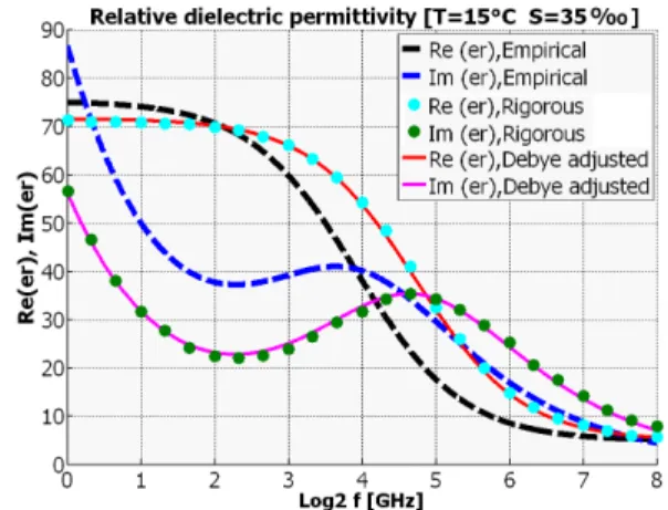
published literature, simple empirical formulas are proposed for these parameters [1]. Moreover, a rigorous model based on the electrophysiology of seawater [2] demonstrates an excellent correspondence between simulations and measurements. Unfortunately, the calculation of the rigorous model involves substantial experimental characterization, thus considerably reducing the possibilities of use. Fig. 1 illustrates that for standard conditions of underwater medium, variations of predictions between the two models (empirical [1] and rigorous [2]) could induce a significant impact on the
attenuation assesment in seawater of electromagnetic waves at around 2.4 GHz frequency.
Fig. 1. Comparison of the dielectric permittivity models of seawater
Furthermore, Fig. 1 also demonstrates that the empirical model can be adjusted (Debye adjusted) to obtain an excellent correspondence with the rigorous model
2.b. Attenuation
The expression of the linear attenuation α (m-1) for the plane wave in a medium is calculated from the homogeneous Helmholtz equation. It leads to:
( )
(
)
1/ 2 21
'
1 tan
1
2
α ω µε
=
+
δ
−
Eq (2)where ε’ is the real part of the dielectric permittivity and tanδ the loss tangent which integrates the conductivity contribution. Considering the frequency at 2.4 GHz, while the rigorous model predicts an attenuation of 7.2 dB / cm, the empirical model provides an additional 4 dB / cm, notably due to a difference in the imaginary parts. Significant uncertainties remain in the theoretical evaluation of the attenuation of radio waves according to the different compared models. Moreover, special care to the sensitivity of the antenna's performances will have to be taken, due to the natural electrical properties variability of the sea water regarding the various local conditions.
OCEANS 2011, June 6th -9th, Santander SPAIN
3.
Ongoing study of the underwater
antenna
3.a. Specification of constraints and objectives
There is a need for fast wireless transmission of large computer video files, or even real-time video using an antenna system integrated in underwater mobile module. Another important requirement is the effective low cost. Moreover, there are some constraints concerning biofouling and hydrostatic pressure, bearing in mind that the oceanic trenches are a part of the objectives of operational implementation.
3.b. Antenna solution for transmission
In the context of air radio transmissions through biological tissues, the solutions combining radiating elements and element protection (buffer) have been successfully developed [3]. In this way, the additional use of circular polarization was firstly suggested to overcome any constraints regarding the azimuthal alignment between transmitter and receiver. But the usual shapes of underwater equipment led us to consider a cylindrical buffer. The study of eigen modes in this buffer demonstrates that the resonant frequency of the TM010 mode does not depend on the height and results in
an azimuthal symmetry; thus this obviates the complexification added for a circular polarization while maintaining the advantages of lack of constraint concerning azimuthal alignment.
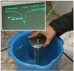
The electromagnetic simulations and optimizations were made by using ANSYS/HFSS ® software (implementing the finite element numerical method FEM). The proposed antenna system is very insensitive to variations of seawater electrical properties dispersions. As shown in Figure 2, we conducted the first experiments which demonstrate the very good abilities to match the system in seawater. Indeed, the return loss (S11) is close to -20
dB, while we verified that the water level variations in the buffer do not shift the working frequency of 2.370 GHz.
Figure 2. Matching measurements on prototype at 2.4 GHz.
4.
Conclusion
A first prototype of underwater antenna at 2.4 GHz has been developed with a very good return loss of -20 dB. The experiment confirms the specific properties selected for applications in various seawater conditions (temperature, salinity, depth ...) without the requirements imposed by azimuthal alignment between the transmitter and the receiver. The experimental study of the transmission is in progress and will permit to verify the hypothesis of the medium modeling and permit to measure the reachable distance of the transmission. For instance it is expected to reach about 10 cm to 15 cm with wireless Wi-Fi conventional systems.
5.
Bibliography
[1] A.Stogryn, “Equations for calculating the Dielectric Constant of saline water”,IEEE Trans on Microwave Theory and Techniques, August 1971, pp 733-736
[2] R. Somaraju, J. Trumpf. ‘Frequency, Temperature and Salinity Variation of the Permittivity of Seawater’’, Antennas and Propagation, IEEE Transactions on Volume 54, Issue 11, Part 2, Nov. 2006, pp 3441 - 3448
[3] J. Kim, Y. Rahmat-Samii “Implanted Antennas Inside a Human Body: Simulations, Designs, and Characterizations”, IEEE Transactions on Microwave Theory and Techniques, Vol. 52, No. 8, August 2004, pp1934-1943