HAL Id: hal-02920621
https://hal.archives-ouvertes.fr/hal-02920621
Submitted on 24 Aug 2020
HAL is a multi-disciplinary open access archive for the deposit and dissemination of sci-entific research documents, whether they are pub-lished or not. The documents may come from teaching and research institutions in France or abroad, or from public or private research centers.
L’archive ouverte pluridisciplinaire HAL, est destinée au dépôt et à la diffusion de documents scientifiques de niveau recherche, publiés ou non, émanant des établissements d’enseignement et de recherche français ou étrangers, des laboratoires publics ou privés.
Highly efficient collective coupling between laser diode
array and lensed fibre ribbon
Philippe Chanclou, Monique Thual, Jean Lostec, Patrick Auvray, J. Caulet,
G. Joulie, A. Poudoulec, Benedicte Clavel
To cite this version:
Philippe Chanclou, Monique Thual, Jean Lostec, Patrick Auvray, J. Caulet, et al.. Highly efficient collective coupling between laser diode array and lensed fibre ribbon. Electronics Letters, IET, 1998, 34 (3), pp.273. �10.1049/el:19980108�. �hal-02920621�
Reprinted from ELECTRONICS LETTERS, 5th February 1998, Vol. 34, N°3, pp. 273-274
Reprinted from ELECTRONICS LETTERS, 5th February 1998, Vol. 34, N°3, pp. 273-274
Highly Efficient Collective Coupling Between
Laser Diode Array and Lensed Fibre Ribbon.
Philippe Chanclou, Monique Thual, Jean Lostec,
Patrick Auvray, J. Caulet, G. Joulié, A. Poudoulec, and Benedicte Clavel. FRANCE TELECOM, CNET, DTD/CAI
2, avenue Pierre Marzin, 22307 LANNION CEDEX
Abstract A new concept is proposed for lensed fibres fabricated according to a collective and low cost process. This process is based on cleaving and splicing of optical fibre ribbons and is suitable for the coupling of laser diode arrays and fibre ribbons.
1. Introduction
The introduction of optical communications into the access network involves reducing the cost of optical components. Regarding transceiver modules in the central office, a way to lower packaging cost, could be to apply the collective and passive alignment process ( without activating the laser array during alignment ). For this the reason the characteristics of optics should be compatible with the packaging tolerances and allow to achieve an effective coupling [1]. The main features [2,3] of this coupling arrangement are high efficiency coupling, relaxed alignment tolerances, long working distance, small packaging volume and low cost fabrication process.
2. Principle and fabrication
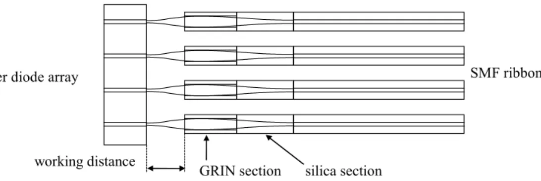
Fig. 1. Schematic representation of optical coupling arrangement between the LD array and SMF ribbon.
In the present paper, a new concept [4] proposed for a lensed fibre ribbon, requires a simple collective fabrication process. As shown in Fig. 1., this optics consists of a graded index (GRIN) fibre section which acts as a GRIN lens [5]. This latter is maintained at the proper distance to the single-mode fibre (SMF) by a coreless silica fibre section. The micro-optics are made with standard ribbons composed of four 250 µm spaced fibres. We used the G652 single-mode fibre and 85/125/250-Alcatel graded index fibre.
silica section GRIN section
working distance
SMF ribbon laser diode array
Reprinted from ELECTRONICS LETTERS, 5th February 1998, Vol. 34, N°3, pp. 273-274
Reprinted from ELECTRONICS LETTERS, 5th February 1998, Vol. 34, N°3, pp. 273-274
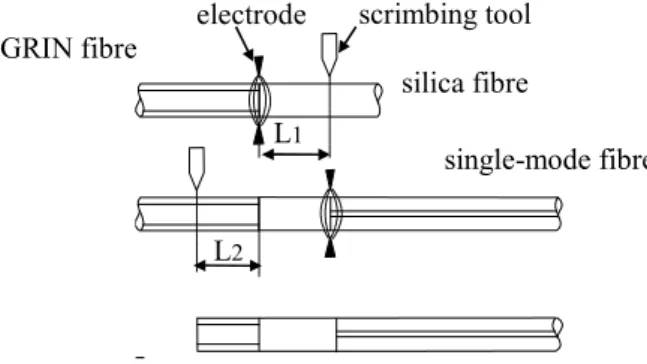
Fig. 2. Schematic illustration of the micro-optics Fig. 3. Photograph of the micro-optics ribbon. fabrication process.
The fabrication process is illustrated in Fig. 2. Using an arc-discharge fibre splicer, the GRIN ribbon is first spliced to the silica ribbon. The silica ribbon is then cut at a distance L1
from the silica/GRIN splicing. The GRIN and silica ribbon are spliced to the SMF ribbon. Finally the GRIN part of ribbon is cut at a distance L2 from the silica/GRIN splicing. The two
splicing losses are below 0.1 dB. Fig. 3 shows a view of the micro-optics ribbon. The reproducibility of the lengths is about 2 µm for each section of ribbon. The external fibre diameter of 125 µm is maintained along the lensed fibres. Note that this collective micro-optics ribbon only requires a collective fibre splicer and cleaver.
3. Optical Coupling Characteristics
The micro-optic ribbon is held in a silicon fibre-carrier fitted with four 250 µm spaced v-grooves. The LD used in experiments had an operating wavelength of 1.3 µm. Light emitting half angles (and radius mode) defined by the far-field at 1 e of the maximum 2
intensity are 25° ( = 0.89 µm) and 30° ( = 0.71 µm) in the parallel and perpendicular directions against the epitaxial surface, respectively. Fig. 4. shows the lensed ribbon coupled with the LD array. In order to measure the homogeneity of the micro-optic ( Fig. 5. ), the coupling efficiency of each fibre of the ribbon is measured at the optimum position in front of the same LD. The coupling efficiency defined as 10log(Pcoupled/Pemitted LD) is -4.540.04 dB for
a working distance of 480.8 µm.
Theoretical coupling loss either by beam propagation method, or by propagation of gaussian beam [6] is -4.5 dB ( not detailed in this paper ).
Laser Diode Coupling Loss dB Working Distance µm fibre 1 -4.5 48.7 fibre 2 -4.58 48.2 fibre 3 -4.55 47.6 fibre 4 -4.54 47.2
Fig. 4. Photograph of four-channel LD array Fig. 5. Optical coupling efficiency of each fibre of the ribbon chip coupled with a micro-optic ribbon. measured at the optimum position in front of the same LD.
The measurements of the coupling loss as a function of axial and lateral displacements are shown in Fig. 6. The optical coupling of the micro optic is compared with a butt coupling of SMF. Loss increments due to displacements in the x and y directions are roughly the same, that is why only one curve is plotted. The optical alignment tolerance is 9 µm for the axial
GRIN fibre silica fibre single-mode fibre L1 L2 scrimbing tool electrode
Reprinted from ELECTRONICS LETTERS, 5th February 1998, Vol. 34, N°3, pp. 273-274
Reprinted from ELECTRONICS LETTERS, 5th February 1998, Vol. 34, N°3, pp. 273-274
direction for 1 dB loss. The micro-optics is better than SMF in the range between +20 µm and -40 µm for axial displacement. The lateral tolerance is 1 µm for 1 dB loss. For this displacement the micro-optic is better than SMF in the 2.4 µm range.
Since no anti-reflecting coating was applied, the -26 dB Fresnel reflection of the air/GRIN interface was measured using an optical coherent domain reflectometer. The two other splicing interface reflections were as low as -80 dB. Nevertheless the oscillation amplitude of the coupling loss along z axis was less than 0.2 dB due to the rather long working distance.
(a) -16 -14 -12 -10 -8 -6 -4 -2 0 0 20 40 60 80 axial displacement (µm) c o u p li n g l o s s ( d B ) (b) -35 -30 -25 -20 -15 -10 -5 0 -4 -2 0 2 4 lateral displacement (µm) co u p lin g lo ss ( d B )
Fig. 6. Coupling-loss characteristics as a function of axial displacement (a) and lateral displacement (b).
4. Conclusion
Our arrangement provides several attractive features with respect to conventional coupling techniques. The lensed fibre ribbon is fabricated using a collective and simple process which allows reproducibility and mass-production. Long working distances, relatively high coupling efficiency and large positioning tolerances have been obtained. The new concept is promising for production of multichannel optoelectronic modules.
Acknowledgement
The authors would like to thank, N. Devoldère for preparing silicon submounts, P. Grosso for providing silica fibres.
References
[1] L. G. Cohen, Microlenses for coupling junction lasers to optical fibers, Appl. Opt, Jan 1974, Vol. 13., N°1, pp 89-94.
[2] N. Kalonji, J. Semo, High efficiency long working distance laser diode to single-mode fiber coupling arrangement, Electronics Letters, 1994, Vol.30 N°11, pp. 892-893. [3] K. Shiraishi, A fiber with a long working distance for integrated coupling between laser diodes and single-mode fibers, Journal of Lightwave Technology ,August 1995, Vol.13, N°8, pp 1736-1744.
[4] M. Thual, J. Lostec, P. Auvray, B. Clavel, French patent N° 96 10327, August 1996. [5] William L. Emkey, Curtis A. Jack, Analysis and evaluation of graded-index fiber lenses, Journal of Lightwave Technology, sept. 1987, Vol. 5, N°9, pp 1156-1164.
[6] H. Kogelnick, Laser Beams and Resonators, Proc. IEEE, Oct. 1966, vol.54, N°10,
pp. 1312-1329.
micro-optic
butt coupling x y z