Science Arts & Métiers (SAM)
is an open access repository that collects the work of Arts et Métiers Institute of Technology researchers and makes it freely available over the web where possible.
This is an author-deposited version published in: https://sam.ensam.eu
Handle ID: .http://hdl.handle.net/10985/6759
To cite this version :
Julien GOMAND, Ghislain REMY, Abdelmounaïm TOUNZI, Pierre-Jean BARRE, Jean-Paul HAUTIER - Impact of Permanent Magnet Field on Inductance Variation of a PMLSM - In: 2007 European Conference on Power Electronics and Applications, Denmark, 2007-09-02 - 2007 European Conference on Power Electronics and Applications - 2007
Any correspondence concerning this service should be sent to the repository Administrator : archiveouverte@ensam.eu
Impact of Permanent Magnet Field on Inductance Variation of a PMLSM
Julien Gomand
1, Ghislain Remy
1, Abdelmounaïm Tounzi
2, Pierre-Jean Barre
1,
and Jean-Paul Hautier
1Laboratoire d’Electrotechnique et d’Electronique de Puissance de Lille (L2EP)
1
Ecole Nationale Supérieure d'Arts et Métiers
8 boulevard Louis XIV
59046 Lille, France
2
Université des Sciences et Techniques de Lille
Bâtiment P2
59655 Villeneuve d’Ascq, France
Tel.: +33 / (0) – 320.622.246.
Fax: +33 / (0) – 320.622.759.
E-Mail:
pierre-jean.barre@lille.ensam.fr
URL: http://l2ep.univ-lille1.fr
Acknowledgements
This work has been supported by Ralph Coleman of ETEL’s Motion Control Research Team, who works actively with the L2EP laboratory of Lille, France.
Keywords
Linear drive, Modelling, Estimation technique, Synchronous motor, Harmonics.
Abstract
Analytical models of Surface Mounted Permanent Magnet Linear Synchronous Motors are generally presented with constant inductances. However, the impact of powerful rare-earth PMs in the saturation phenomena cannot be neglected anymore. In this paper, a new non-linear model of PMLSM inductances is suggested. This model is defined as a function of the current value as well as of the magnet position. So, an analytical study, a finite-element analysis and experimental results are presented and confronted.
1. Introduction
Surface Mounted Permanent Magnet Linear Synchronous Machines (PMLSM) are widely used in the industrial framework [1]. These structures permit to achieve very high performances (power to weight ratio, high dynamics) [2]. The PMLSM’s are often used as components for high-speed positioning systems, such as “Pick & Place” applications with a Gantry system [3]. Most of the time, the typical duty cycle uses high accelerations during short times, according to the energetic limitation induced by the I²t value of the actuator. So the supply pulse current could be greater than the continuous rated current, which could imply saturation phenomena in the ferromagnetic sheets.
On the other hand, the PMLSM performances have been increased using rare-earth permanent magnets which have a very high residual magnetic flux density [4]. Besides, during the last decades, the price of PM such as Nd-Fe-B becomes more and more accessible [5]. The use of such PM leads to consider some modifications on the operating of the PMLSM. Indeed, due to the significant value of their residual flux density, the PM thickness needed is much smaller than in the case of the ferrite PM. This leads to a smaller equivalent air-gap with a high value of magnetic flux density, which is often close to the saturation level of the ferromagnetic sheets. Usually, for surface mounted PM synchronous motors, the inductances are assumed to be constant in classical models [6]. With the saturation phenomena, the inductances have to be taken as functions of both the current value and the magnet position.
First, an analytical model of the inductance variations is presented. The influence of both current and position variables is explained from an asymptotical point of view. The representation of the model is then obtained using the Causal Ordering Graph formalism. In a second part, the finite-element analysis using 2D-FEM software is presented. In the final part, experimental results are presented and compared with the finite element analysis. The measurement procedure is particularly detailed.
The investigated PMLSM is a flat ironcore LMD10-050 from Etel (Fig. 1). Table 1 lists some specifications of the PMLSM. This linear motor is a one pole pair structure with a pole pitch
τp = 16mm, and a force constant Kt of 88.8N/A. The air gap thickness is about 0.8mm and the Neodymium-Iron-Boron permanent magnets have a residual flux density of approximately 1.23Tesla.
Table I: Specifications of the LMD10-050 [7]
Rated Current Maximal Current Detent Force Rated Thrust Maximal Thrust
2Arms 7.9Arms 5N 130N 554N
Fig. 1: Structure of the linear actuator LMD10-050 [8]
2. Analytical model
The PMLSM studied is shown in figure 1. It is composed of a moving part (primary) and a fixed magnetic way (secondary). It is different from classical linear synchronous machines, as the magnet pole pitch τp is smaller than the tooth pitch of the primary. Moreover, the ratio between both pole pitches has been designed so that the induced electromotive forces are sinusoidal functions of the secondary position [9], [10]. Besides, each armature phase of the machine is composed of two pole concentrated coils (Fig. 1). The electrical model of this PMLSM can be described by the classical relation [11]:
[ ] [ ] [ ]
abc abc abcd
v
R i
dt
φ
= ⋅
+
(1)The three phase windings are star-connected, and the neutral-wire is accessible, but not connected. The winding distribution causes the mutual inductances to be negligible. Thus, the study of the non-linearity effects on a phase is independent from the other two. So, the flux of phase a is only a function of the current ia and the position of the magnets x:
( )
,
a a a a a ad
x i
di
dx
dt
i
dt
x dt
φ
∂
φ
∂
φ
=
⋅
+
⋅
∂
∂
(2)Then, we define the dynamic inductance La_dyn as the partial derivative of the flux linkage with regard to the current, for a given position [12]:
( )
( )
_,
,
a a a dyn a ai x
L
i x
i
φ
∂
=
∂
(3)The general shape of the evolution of dynamic inductances can be deduced from a relatively simple reasoning based on the study of the variation of the magnetic permeability µ of the material, according to the magnetic field H. In Fig. 2a, the simplified magnetic characteristic B(H) is composed of two different values of permeability: µ0 in the saturated part, and µ0·µr in the linear part of the material, where µr = 4500. These values relate to the lower (saturated material) and the higher (linear zone) values, respectively Lsat and Llin, on the dynamic inductance curve (Fig. 2b). The tooth magnetic field due to the magnets, Hm, varies with respect to the secondary position. It then constitutes a variable offset magnetic value. For a given position, the current Isat+, which is necessary to reach the “positive saturation” level Hsat in the teeth, is proportional to ΔH+ = Hsat - Hm. For the same position, the current
Isat-, necessary to reach the “negative saturation” level -Hsat, is proportional to ΔH- = Hsat + Hm. These values, Isat+ and Isat-, obviously depend on Hm and then on the secondary position, as shown in Fig. 2b. For the other two phases, the inductance variations can be deduced from those of phase a by a spatial phase shifting of ± 2·τp/3.
Fig. 2: Simplified B(H) and dynamic inductance curves
In order to analyse the influence of the dynamic inductance evolution on the PMLSM model, we use the Causal Ordering Graph (COG) formalism [13]. Indeed, the COG is based on a located energy representation with the theory of causal ordering [14]. It is undeniable that this approach is connected with that of links graphs such as the Bond Graphs [15]. But it differs from them by the analysis process, which is only based on integral causality. The COG is a tool that structures the synthesis of a state model, but that aims at maintaining, for a given system, a representation that stays as close as possible to its physical behaviour. In general, the expression of the transformation relations by means of the state equations is the best warranty against physical misinterpretation.
In the COG formalism, two complementary definitions of the causality are used. The corresponding COG symbols are presented in Fig.3:
• If an object accumulates information, the causality is internal. The output is necessarily a function of the energy state. The relation, thus oriented, is known as causal. The corresponding causal processor is given in Fig. 3a. Time and the initial state are implicit inputs and are not represented.
• On the contrary, if an object does not accumulate any information, causality is external. The output is thus an instantaneous function of the input. The relation, which is not oriented, is then known as rigid (Fig. 3b).
R R
( )
u t y t( )
u t( )
y t( )
0 0 ( ) ( ( )) ( ) ( ) ( ) t t R y t y t u u t dt a α = → = +∫
( ) ( , ). ( ) ( ) R y t u t u t b α → = R R( )
u t y t( )
u t( )
y t( )
0 0 ( ) ( ( )) ( ) ( ) ( ) t t R y t y t u u t dt a α = → = +∫
( ) ( , ). ( ) ( ) R y t u t u t b α → = R R( )
u t y t( )
u t( )
y t( )
0 0 ( ) ( ( )) ( ) ( ) ( ) t t R y t y t u u t dt a α = → = +∫
( ) ( , ). ( ) ( ) R y t u t u t b α → =Fig.3: COG symbols:
The Causal Ordering Graph of the PMLSM is presented in Fig. 4. To facilitate the knowledge of the three phase modelling, this model is defined as a vector scheme. We notice in Eq.2 that the time derivative of the flux in the saturated case is considered as the sum of the flux partial derivative of the current function and flux partial derivative of the magnet position function. Using the COG, the calculation of these two partial derivatives is represented in the R6 processor. Indeed, in the saturated case, the flux has to be considered as a global function of the current and the magnet position. The ∂Φ/∂i is then used in the R2 processor, as the dynamic inductance to calculate the current value. The ∂Φ/∂x is used in the R5 processor, as the back electromotive force coefficient. The ∂Φ/∂x term is also used in the R4 processor for the electromechanical conversion. As the ∂Φ/∂x and the ∂Φ/∂i relations are time independent, the R6 processor can be considered as rigid. The R4 and the R5 processors are linked together as a gyrator [13]. That is classically known as a reversible electromechanical conversion. 1 R VLabc R2 Tem abc e abc V 7 R 10 R 8 R s f T +T mot T x v 3 R Rabc V iabc 5 R 6 R v 9 R x v abc i Tr abc e / abc i φ ∂ ∂ 4 R / abc x φ ∂ ∂ 1 R1 R VLabc R 2R2 Tem abc e abc V 7 R 7 R 10 R10 R 8 R 8 R s f T +T mot T x v 3 R 3 R Rabc V iabc 5 R 5 R 6 R 6 R v 9 R 9 R x v abc i Tr abc e / abc i φ ∂ ∂ 4 R 4 R / abc x φ ∂ ∂
Fig. 4: COG representation of a PMLSM with saturation phenomena
Table II: Relation of the COG representation
Electrical Model: Mechanical Model:
1 Labc abc abc Rabc
R →V =V −e −V 4 ( ) , , , k k em k k a b c i x R T i x φ = ∂ → = ⋅ ∂
∑
(
)
2 ,abc abc abc
Labc abc i x di R V i dt φ ∂ → ⋅ = ∂ R7 →Tmot =Tem− − −Tr Ts Tf 3 Rabc abc R →V = ⋅R i
,
5(
)
, abc abc abc i x R e v x φ ∂ → = ⋅ ∂ 8 mot dv R M T dt → ⋅ =,
9 dx R v dt → =(
)
(
)
(
)
(
)
6 , , , , abcabc abc abc abc
abc abc x cst
abc abc abc abc
i cst i x d i x i di R i x d i x x dx φ φ φ φ = = ∂ = ∂ → ∂ = ∂ 10 , 0 , 0 v s f v Ts f v si v R T T Ts f v si v + ⋅ > ⎧ → + = ⎨ − + ⋅ < ⎩
3. Finite Element Analysis
To identify the dynamic inductances, we have solved a numerical model using the two-dimensional Finite Element (2D-FEM) calculation software called FEMM [16].
Because of the particular structure of the studied PMLSM, end effects of the finite length primary of the linear machine have to be taken into account. The finite element calculations are thus achieved with the complete actuator structure. On the other hand, the winding end effects cannot be taken into account with the 2D-FEM software. The non linear magnetic characteristic of the iron is taken into account with an average B(H) curve. Fig. 5 shows the primary of the LMD10-050 in two different positions with no supply current, according to the description of Fig. 1:
- The d-axis position (x = 0), where one “North” magnet induces an important induction value in phase a. Position x is defined as the distance between the a-axis of the primary and the d-axis of the secondary.
- The q-axis position (x = τp/2), where phase a receives as much flux from one “South” magnet as from one “North” magnet.
Fig. 5 shows that the induction level in the teeth of phase a, for the d-axis position, is close to 1.6 Tesla. In consequence, the saturation phenomena in the ferromagnetic circuit can be reached more easily in the d-axis position than in the q-axis position.
Fig. 5: Influence of permanent magnets position on the magnetic state of the structure with 2D-FEM calculations (ia = ib = ic = 0)
For a given current value ia and a given position x, the dynamic inductance La_dyn(ia, x) calculation is based on two flux values Φa1 (ia1,x) and Φa2 (ia2,x) obtained with a "little" current variation Δia = ia2 ia1. The dynamic inductance is thus calculated for the current value ia = (ia1 + ia2) / 2:
( )
1 2 _ 1 2 0 , b c a a a a dyn a a a a i i L i x i i iφ
φ
φ
= = − Δ = = − Δ (4)For accurate results, the current variation Δia has to be sufficiently weak to allow the linearization of the magnetic characteristic while limiting error on its slope. However, this variation must be sufficient to ensure the independence of results from the inaccuracy of this B(H) characteristic. Some experience has shown that a 0.01 Ampere Δia value is a good compromise.
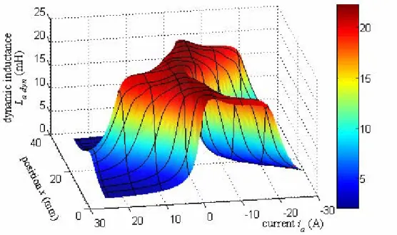
Fig. 6 presents the finite element calculation results for the dynamic inductance of phase a.
That confirms the illustration of Fig. 2 on the influence of the magnet position in the saturation phenomena. The calculations are performed with constant currents (magnetostatic case) which correspond here to an instantaneous current value. Additionally, the iso-position and iso-current curves are plotted over the 3D-Plot of the dynamical inductance in Fig.6.
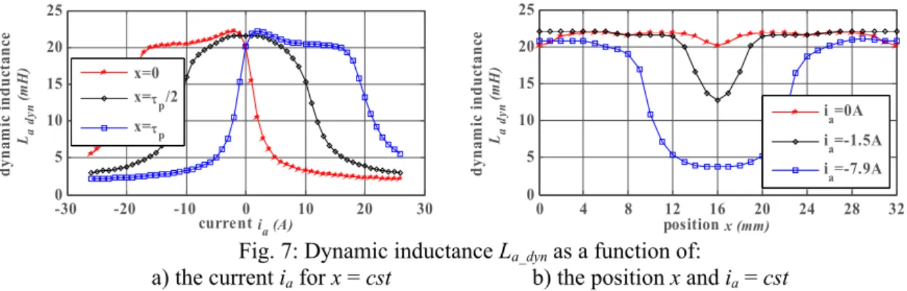
Fig. 7a shows the variation of the dynamic inductance La_dyn as a function of the current ia for 3 different positions of x. For x = τp/2 = 8mm, the tooth of phase a is up to the middle of two opposite polarity magnets. So the saturation phenomenon is reduced. For x = 0mm the tooth of phase a is up to a North magnet. So the saturation phenomenon is maximal for positive current values. The impact of the permanent magnet could be considered in Fig.7a, as a shifting of an equivalent sinusoidal current with a peak-to-peak value of about 18A. This peak-to-peak value is inversely proportional to the air-gap thickness. -30 -20 -10 0 10 20 30 0 5 10 15 20 25 current ia (A) d yna m ic i n du ct an ce La dy n (m H ) x=0 x=τp/2 x=τp 0 4 8 12 16 20 24 28 32 0 5 10 15 20 25 position x (mm) dy na m ic i ndu ct an ce La dy n (m H ) ia=0A ia=-1.5A ia=-7.9A
Fig. 7: Dynamic inductance La_dyn as a function of:
a) the current ia for x = cst b) the position x and ia = cst
Fig. 7b shows the variation of the dynamic inductance La_dyn as a function of position x for 3 different currents ia (no current, rated current, peak current). For x = τp = 16mm, phase a is up to a South magnet, so a negative current value increases the impact of the magnet position on the saturation phenomenon. With the maximal current value, the dynamic inductance is decreased by 80%.
4. Experimental validation
The proposed model is experimentally verified on a laboratory test system equipped with an ETEL LMD10-050 linear motor (Fig. 9). A Heidenhain exposed linear encoder with a grating period of 20µm is used to detect the mover position. A dSPACE DS1005 real-time card is used for the identification procedures. The linear motor is star-connected, with an accessible neutral wire.
Voltage Source real-time processor dSPACE 1005 Supervision computer 20 µm encoder va(t) ia(t) x(t) voltage reference Voltage Source real-time processor dSPACE 1005 Supervision computer 20 µm encoder va(t) ia(t) x(t) voltage reference Voltage Source real-time processor dSPACE 1005 Supervision computer 20 µm encoder va(t) ia(t) x(t) voltage reference
During the experiments, one phase of the PMLSM is supplied with a controlled sinusoidal voltage source (Fig. 9). According to Eq. 3, the dynamic inductance of phase a can be experimentally obtained while maintaining the primary in a given position. Fig. 10a shows the supplied voltage and the resulting non sinusoidal current, when x = τp. During measurements, the current has been limited to the maximal admissible value of the peak current for the LMD10-050 (Table 1). Theoretically, it is possible to reach a higher current value using voltage pulses (close to the 26A of the finite elements results presented in Fig. 6).
The time variation of the flux in the studied phase is then obtained thanks to a time integration of the voltage and current measurements [17]:
( )
(
( )
( )
)
a t v t R i t dta a
φ
=∫
− ⋅ ⋅ (5)The resulting non linear characteristic Φ = f(i) is presented with position x = τp (Fig. 10b). The effect of the non symmetrical saturation phenomena induced by the "South" magnet can be observed on both current and flux waveforms. The previously neglected hysteresis phenomenon induced by the ferromagnetic sheets can also be noticed. According to Eq. 3, the dynamic inductance of the considered phase is then deduced from an average non linear flux characteristic.
0.09 0.1 0.11 0.12 0.13 0.14 0.15 -60 -40 -20 0 20 40 60 t (s) vo lta ge (V ), c urre nt (A ) Van (V) ia (A) ialin (A) -10 -7.5 -5 -2.5 0 2.5 5 7.5 10 -0.2 -0.15 -0.1 -0.05 0 0.05 0.1 0.15 0.2 flu x φ an (W b) ia (A)
Fig. 10: Experimental identification:
a) voltage and current measurements b) non linear flux characteristic Φ=f(i)
In Figure 11, the experimental dynamic inductance of phase a is compared to the FEM results when
x= τp. In this position, the tooth of phase a is up to a South magnet. The experimental identification results are about 10% higher than the finite element ones. This difference can be attributed to end-winding leakage inductances that are impossible to take into account with 2D FEM calculations. To achieve accurate 3D-FEM calculations, the number of elements has to be dramatically increased, leading to unacceptable computation time. Indeed, the required computation time to reach the 2D-FEM results is about 10 days on 4 PCs with 3GHz and 1GB RAMBUS.
-30 -20 -10 0 10 20 30 0 5 10 15 20 25 current ia (A) dy na m ic i n du ct an ce La dy n (m H ) LdynFEM Ldynex p
These end-winding effects are then approximately compensated in Fig. 12, increasing the FEM results (Fig. 6) by around 10% of the La_dyn value. Experimental La_dyn curves are given for three different positions (x = τp / 3, x = τp and x = 5·τp / 3) and are in good accordance with FEM results.
Fig. 12: Comparison of dynamic inductance La_dyn for x = τp
5. Conclusion
In this paper, the inductance variations of a Surface Mounted Permanent Magnet Linear Synchronous Motor have been studied as a function of both the current and the magnet position. This non conventional approach is due to the saturation phenomena induced by the use of permanent magnets with very high residual magnetic flux density.
First, we have highlighted the origin of the saturation phenomena of the inductances. The proposed analytical model of the surface PMLSM is based on the dynamic inductances as a function of both the current and the position. Finite element analysis and experimental measurements validate the analytical model of the inductances proposed in this paper. Experimental results show a 10% error mainly caused by the neglected end-winding leakage inductances. As these effects cannot be integrated using 2D-FEM software, a future paper will describe a simplified 3D-FEM, regarding some computation time considerations.
Saturated inductances have many effects for the control design: non sinusoidal current, ripple thrust, peak thrust limitation. The study presented in this paper allows us to investigate further control design to reduce the saturation effects.
References
[1] Cassat A., Corsi N., Wavre N., and Moser R.: Direct Linear Drives: Market and Performance Status, Proc. of the 4th Int. Symp. on Linear Drives for Industry Applications, LDIA 2003, Birmingham, UK, Sept. 2003 [2] Gieras J.F.: Status of Linear Motors in the United States, Proceedings of the 4th International Symposium on
Linear Drives for Industry Applications, LDIA 2003, Birmingham, UK, Sept. 2003
[3] Widdowson G.P., Youyong L., Gaunekar A.S., Kuah T.H., Srikanth N.: Design of a high speed linear motor driven gantry table, 1998 International Conference on Power Electronic Drives and Energy Systems for Industrial Growth, Proceedings 1998, Vol. 2, pp. 936-941, Dec. 1998.
[4] Mueller M.A., Baker N.J.: Modelling the performance of the vernier hybrid machine, IEE Proceedings on Electric Power Applications, Vol. 150, No. 6, pp. 647-654, Nov. 2003
[5] Benecki W.T.: World Wide Market Situation or Flow of Magnets, Symposium of the Japanese Association of Bonded Magnet Industries, 2004BM, Tokyo, Dec. 2004
[6] Fitzgerald A.E., Kingsley C., Umans S.: Electric Machinery, McGraw-Hill, 6th Ed, pp. 704, Jul. 2002.
[7] LMD10-050 Datasheet, Etel, http://www.etel.ch/, 2007.
[8] Wavre N.: Permanent-Magnet Synchronous Motor, ETEL patent US 05642013A, Jun. 1997.
[9] Polinder H., Slootweg J.G., Hoeijmakers M.J., Compter J.C.: Modelling of a linear PM Machine including magnetic saturation and end effects: maximum force-to-current ratio, IEEE Trans. on Industry Applications, Vol. 39, No. 6, pp. 1681-1688, Nov. 2003
[10] Bolognesi P., Bruno O., Landi A., Sani L., Taponecco L.: Electromagnetic Actuators Featuring Multiple Degrees-of-Freedom: a Survey, 16th Int. Conference on Electrical Machines, Cracow, Poland, Sept. 2004 [11] Krause P.: Analysis of Electric Machinery, New York: McGraw-Hill, 1986
[12] Vas P.: Vector Control of AC Machines, Oxford University Press, Ch5: Effects of magnetic saturation, 1990
[13] Hautier J.P., Barre P.J.: The causal ordering graph - A tool for system modelling and control law synthesis, Journal of studies in informatics and control, vol. 13, no. 4, pp. 265-283, 2005
[14] Kleer J., Brown J.S.: Theories of causal ordering, Artificial Intelligence 29, Elsevier Science Publishers, 1986, pp. 33-61.
[15] Karnopp D., Margolis D., Rosenberg R.: Systems dynamics: modelling and simulation of mechatronic systems, John Wiley & Sons, 2000.
[16] FEMM, user manual, http://femm.foster-miller.net.
[17] Stumberger G., Stumberger B., Dolinar D.: Identification of Linear Synchronous Reluctance Motor Parameters, IEEE Industry Applications Conference, Conference Record of the 2000 IEEE, vol. 1, pp. 7-14, 2000
![Table I: Specifications of the LMD10-050 [7]](https://thumb-eu.123doks.com/thumbv2/123doknet/7300752.209110/3.892.140.758.304.528/table-i-specifications-of-the-lmd.webp)