This is an author-deposited version published in: https://sam.ensam.eu Handle ID: .http://hdl.handle.net/10985/7335
To cite this version :
Antoine POUTORD, Frédéric ROSSI, Gérard POULACHON, Rachid M'SAOUBI, Guillaume ABRIVARD - Study of the local forces along a drill edge – comparison of two methodologies - In: Congrès Français de Mécanique (21; 2013; Bordeaux), France, 2013-08 - Congrès Français de Mécanique (21; 2013; Bordeaux) - 2013
Study of the local forces along a drill edge –
comparison of two methodologies
A.POUTORDa,F.ROSSIa,G.POULACHONa,R.M’SAOUBIb,G.ABRIVARDc a. Arts et Metiers Paristech, LaBoMaP, Cluny, France
b. SECO Tools, SE- 73782 Fagersta, Sweden c. EADS, Nantes, France
Abstract :
In aerospace applications, drilling is one of the most common operations. However, this machining stays complex and expensive, especially in hard to cut materials. Because of the closed aspect of the operation, the measure or evaluation of the phenomenon on the cutting area is difficult, especially decomposing the forces for various parts of the edge. This study focuses on two methodologies allowing a study of the forces along the drill’s edge.
The first methodology is based on a physical decomposition of the drill edge. This approach, like the following one, is based on the hypothesis of the independency of the segments: each part of the edge is cutting the material independently from its neighbors (for the chip flow or the local forces). By measuring the forces on the drilling of samples of various external diameters, smaller or bigger than the drill diameter, and with or without pilot hole, the reconstruction of the forces along the drill edge and on the margin could be done.
The second methodology, still based on the hypothesis of the independency of the segments, decomposes the forces during the drill point sinking on the material. On each entry altitude, the drill edge engagement is known, allowing the recomposition of the forces along the edge and on the margin.
Experiments have been done to compare the two methodologies with one drill and one batch of Ti6Al4V alloy.
Keywords: Drilling, Local forces, Ti6Al4V, Edge-Material pair
1 Introduction
Aerospace industry uses more and more widely titanium alloys, mostly Ti6Al4V for its high mechanical properties (high strength-to-weight ratio, high strength at elevated temperatures), corrosion resistance and a modulus of elasticity near the carbon fiber composite one, alloying a good repartition of the stresses on stack uses (with carbon fiber reinforced plastic) [1, 2].
On many applications, drilling is a critical operation especially in Ti6Al4V, mainly because of the closed aspect and the physical properties of Ti6Al4V [3]. Most studies are focalized on the global forces to understand the phenomenon and the holes qualities [4] or to simulate thermo-mecanical aspects [5]. To increase the accuracy of the thermo-mechanical models, the local forces along the cutting edge have to be known, as R. Li [6, 7] has shown.
Few methods developed to decompose the forces along the edge of a drill could be presented in two mains categories, the first one is based on a physical decomposition of the drill’s edge and the second one decompose the drill point engagement.
material [12-14].
The comparison between both methods, including the strengths and the weaknesses of each ones is developed in this paper.
2 Experimental procedures
2.1 Experimental tooling and equipment
Ti6Al4V alloy sample of 20 mm diameter is obtained by aerospace industry. The thermo-mechanical treatment of the plate is called titanium β.
Machining experiments were performed on a two axis lathe (SOMAB Transmab 400) with a spindle speed of 8000 rpm. Ti6Al4V sample was taken with an ER32 collet on the lathe chuck. The thrust force and torque were measured by a Kistler 9121 dynamometer calibrated for the torques measurement. The Z axis and spindle position were acquired respectively by the optical rules with a 0.1 µm and 0.35° resolution. Signals were monitored by an A/D board (NI 9188 and three NI 9215 cards, National Instrument, USA, with a 50 kHz data acquisition frequency) and recorded on a PC using data acquisition software (Dasylab 11, NI, USA). The data were then operated with Matlab R2007b software
A commercial drill (Seco – K20 type uncoated) recommended for titanium drilling was selected for this investigation. Main cutting tool parameters are listed in Table 1.
Wc drill (Grade K20) Drill diameter 12 mm Flute length 55 mm Point angle 140° Helix angle 30° Back taper 0.5 %
TABLE 1 – Drill geometry
2.2 Experimental design
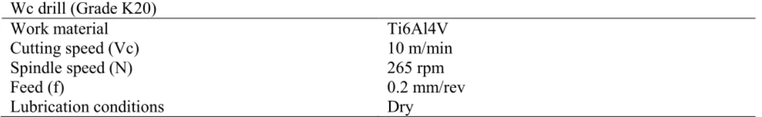
A previous study of tool/material pair has been done to select suitable cutting parameters. The drilling cutting conditions chosen for this study are summarized in Table 2.
Wc drill (Grade K20)
Work material Ti6Al4V
Cutting speed (Vc) 10 m/min
Spindle speed (N) 265 rpm
Feed (f) 0.2 mm/rev
Lubrication conditions Dry
TABLE 2 – Cutting conditions
A wear study of a drill selected in the same batch showed that the global cutting forces do not change significantly during the firsts 18th holes during drilling Ti6Al4V [15]. That point has been confirmed by a
repetition of the first drilling test at the end of the experimentation.
2.2.1 Physical decomposition
The first methodology employed to decompose the edge is based on a “physical decomposition”. Few edge portions of the drill are used during the drilling of sample of various external diameters and with or without pilot hole as showed in Fig. 1 & 2. The local forces are deduced by the global forces of each experiment. Table 3 presents the machining tests carried out in order to correlate the local forces with seven sections of the edge drill. The pilot hole permits the physical subtraction of the chisel influence on the drilling operation.
FIG. 1 – Physical drill decomposition Test # Pilot hole [mm] Outside Ø [mm] e [mm]
1 3 mm 19 mm 4.5 mm 2 3 mm 11.9 mm 4.45 mm 3 3 mm 11 mm 4 mm 4 3 mm 9 mm 3 mm 5 3 mm 7 mm 2 mm 6 3 mm 5 mm 1 mm 7 No pilot hole 19 mm 6 mm 8 No pilot hole 11.9 mm 5.95 mm 9 No pilot hole 11 mm 5.5 mm 10 No pilot hole 9 mm 4.5 mm 11 No pilot hole 7 mm 3.5 mm 12 No pilot hole 5 mm 2.5 mm
TABLE 3 – Drilling experiments Edge subdivision # Radius [mm]
1 0-1.5 2 1.5-2.5 3 2.5-3.5 4 3.5-4.5 5 4.5-5.5 6 5.5-5.95 7 5.95-6 margin included
TABLE 4 – Edge subdivision
FIG. 2 – Edge subdivision
2.2.2 Point drill decomposition
The second methodology employed is based on the decomposition of the thrust force and the torque during the progressive penetration of the drill point in the work material, called “point drill discretization”. Figure 3 shows the variation of the thrust force and the cutting torque during the drilling of Ti6Al4V work piece. The study is focusing on the beginning of the drilling as shown in the red box on figure 3. Between the two verticals lines, the edge is more engaged on the X direction by a section presented on table 4. By subtraction of each edge part, the distribution on various sub-division of the edge drill can be deduced.
To compare with the first methodology, the test # 7 has been used to decompose the thrust force and the cutting force.
FIG. 3 – Thrust force and torque during the drilling of the hole with full drill edge engagement (a) forces acquisition during the drilling (b) zoom on the trip drill engagement
To find the distribution of the local cutting force along the main edge, the local torque is calculated like the thrust force in order to determine the local cutting forces. The cutting force is assumed to be constant on each edge segment and the application point of the equivalent local force is calculated for each segment. The choice for the 7th segment on table 4 is done for the both methodologies to allowing the comparison of the
results.
3 Results and discussion
3.1 Thrust force
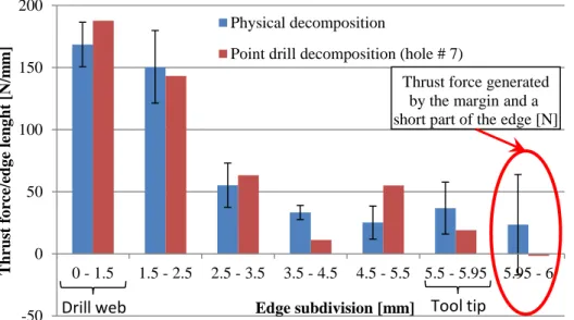
The comparison between the two methodologies for the thrust force is presented on the figure 4. The forces are represented in N/mm in order to facilitate the comparison between each segment that have various lengths.
FIG. 4 – Thrust force distribution along the cutting edge for both methods
Both the local forces repartitions seem to have the same profile. This sameness allows to conclude that both ways to calculate the local forces are quite good in terms of thrust forces repartition along the edge.
The bar dispersions on the physical decomposition are two times the standard deviation on each side of the centered value. The quite low levels of these values with regard to the forces level allow consolidating the idea that the method permits to come back to the thrust force along the edge.
0 2 4 6 8 10 12 0 200 400 600 800 1000 1200 0 5 10 15 20 T o rque [N. m ] T hrus t fo rc e [N]
Position of the tip drill [mm]
Torque
Material: Ti6Al4V sample Machine: 2 axis lathe Vc = 10 m/min f = 0.2 mm/rev 0 2 4 6 8 10 12 14 0 200 400 600 800 1000 1200 1400 0.0 0.5 1.0 1.5 2.0 T o rque [N. m ] T hrus t fo rc e [N]
Position of the tip drill [mm] Torque 0 1.5 3.5 4.5 -50 0 50 100 150 200 0 - 1.5 1.5 - 2.5 2.5 - 3.5 3.5 - 4.5 4.5 - 5.5 5.5 - 5.95 5.95 - 6 T hrus t fo rc e/edg e leng ht [N/m m ] Edge subdivision [mm] Physical decomposition
Point drill decomposition (hole # 7)
Thrust force generated by the margin and a short part of the edge [N]
Drill web Tool tip
A previous study using the drill point decomposition with the same tool and material workpiece, but on a milling machine allows us to add that the standard deviation is around 10 - 15 N/mm for the thrust force [15]. Both methodologies show that the drill web is the drill area where the stress are the higher (around 50% of the global thrust force is from 0 mm to 1.5 mm on the drill edge). This decomposition points out the importance of the drill web for the drilling operation. The other important edge portion of the drill is the tool tip and the margin, the thrust force could be negative on this edge section, tending to turn up the plate during drilling. Moreover, the higher cutting speed on this area increase the power generated on the tool tip and margin.
3.2 Cutting forces
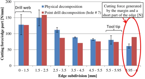
The methodology used to compare the cutting forces is the same as the one used for the thrust force comparison. The figure 5 presents the cutting forces by edge length (N/mm) in order to compare easily the various segments with different lengths.
FIG. 5 – Cutting force along the edge for both methods
Both local forces repartition seems to have the same profile. This sameness allows to conclude that both ways to calculate the local forces are quite good in terms of thrust forces repartition along the edge.
The study of the cutting force shows that the drill web and margin are edge portions that are mainly solicited. The web has a higher cutting force level, but the margin cuts more material, implying a high power spent on this edge subdivision.
3.3 Sensitivity of the models
Both models are based on the hypothesis of the independence of the segments. The only way to confirm this hypothesis is to acquire the forces directly from an edge part, like with split tool, that not seems to be possible for drills yet.
The physical decomposition, based on the machining of multiple samples, implying a highly sensitivity to the tool wear and to the effective edge engagement. Each local force has to be calculated by various combinations of the global drilling forces in order to limit the errors; six combinations are used to calculate the influence of the drill web and four for each other section. Moreover, on a lathe, the coaxiality between the tool and the sample need to be checked, in our case, the defect was inferior to 5/100 mm.
The point drill decomposition is based on the numerical decomposition of the signals of the forces for one drilling, implying a strong sensitivity to the tool geometry, especially the point angle. On our study, the official point angle was of 140°, implying a drill point length of 2.18 mm (on the Z direction), the measured one was 146.6°, associated to a drill point length of 1.8 mm. The numerical calculation must not dephasing
0 50 100 150 200 0 - 1.5 1.5 - 2.5 2.5 - 3.5 3.5 - 4.5 4.5 - 5.5 5.5 - 5.95 5.95 - 6 Cut ting f o rc e/edg e pa rt [ N/m m ] Edge subdivision [mm] Physical decomposition
Point drill decomposition (hole # 7)
Cutting force generated by the margin and a short part of the edge [N]
Drill web
If both methods allow determining the tendency for the local forces along the cutting edge, each ones have some advantages and disadvantages.
From an experimentation point of view, the drill point decomposition method is easily done, the mains constrain are the high velocity acquisition and the high sensitivity to the skin effect of the material (variation of the mechanical properties with the depth drilled). The main advantage is that only one drilling is needed. The physical decomposition is more difficult from an experimentation point of view, many drillings are needed, implying the influence of the drill wear, the various diameter drilled have to be the known with a high precision.
For the extraction of the data, the drill point decomposition need a program more precise to handle the data, the starting point and the point angle have to be known precisely for a good reconstruction. The physical decomposition method has data that can be extracted easily.
The main advantage of the drill point decomposition method is the continuous aspect of this method. The length of the edge segments could be much more fine compare to the physical decomposition method. For the physical decomposition data, repeatability test for each diameter machined should be carried out to confirm the forces level for each parameter set. Some experiments allowing to confirm the hypothesis done on the cutting forces part will be conducted.
References
[1] Ezugwu E.O.,Wang Z.M., Titanium alloys and their machinability - a review, Journal of Materials Processing Technology, Vol. 68, p. 262-274, 1997
[2] Ezugwu E.O., Key improvements in the machining of difficult-to-cut aerospace superalloys, International Journal of Machine Tools & Manufacture, Vol. 45, p. 1353–1367, 2005
[3] Cantero J.L., Dry drilling of alloy Ti6Al4V, International Journal of Machine Tools & Manufacture, Vol. 45, p. 1246–1255, 2005
[4] Dornfeld D.A., Kim J.S., Dechow H., Hewson J., Chen L.J., Drilling Burr Formation in Titanium Alloy, Ti-6AI-4V, CIRP Annals - Manufacturing Technology, Vol. 48, p. 73-76, 1999
[5] Ozcelik B., Bagci E., Experimental and numerical studies on the determination of twist drill temperature in dry drilling - A new approach, Materials & design, Vol. 27, p920-927, 2006
[6] Li R., Shih A.J., Spiral point drill temperature and stress in high-throughput drilling of titanium, International Journal of Machine Tools & Manufacture, Vol. 47, p. 2005–2017, 2007
[7] Li R., Shih A.J., Tool temperature in titanium drilling, Transaction of ASME, Vol. 129, p.740-749, 2007 [8] Dargnat F., Modélisation semi-analytique par approche énergétique du procédé de perçage de matériaux monolithiques, thesis, Université de Bordeaux I, N° 3216
[9] Lee J.E., Gozen B. A., Ozdoganla O. B., Modeling and experimentation of bone drilling forces, Journal of Biomechanics, Vol. 45, p.1076-1083, 2012
[10] Hamade R.F., Seif C.Y., Ismail F., Extracting cutting force coefficients from drilling experiments, International Journal of Machine Tools & Manufacture, Vol. 46, p. 387–396, 2006
[11] Bonnet C., Compréhension des mécanismes de coupe lors du perçage à sec de l’empilage Ti6Al4V Composite fibre de carbone, thesis, ENSAM Cluny, France
[12] Guibert N., Paris H., Rech J., Claudin C., Identification of thrust force models for vibratory drilling, International Journal of Machine Tools & Manufacture, Vol. 49, p. 730–738, 2009
[13] Lazar M.-B., Xirouchakis P., Experimental analysis of drilling fiber reinforced composites, International Journal of Machine Tools & Manufacture, Vol. 51, p. 937–946, 2011
[14] Lazar M.-B., Xirouchakis P., Mechanical load distribution along the main cutting edges in drilling, Journal of Materials Processing Technology, Vol. 213, p. 245-260, 2013
[15] Poutord A., Rossi F., Poulachon G., M’Saoubi R., Abrivard G., Local approach of the wear in drilling Ti6Al4V/CFRP for stack modeling, Procedia CIRP, 2013, in press
![TABLE 3 – Drilling experiments Edge subdivision # Radius [mm]](https://thumb-eu.123doks.com/thumbv2/123doknet/7312545.210123/4.892.74.809.88.908/table-drilling-experiments-edge-subdivision-radius-mm.webp)