HAL Id: hal-00949546
https://hal.archives-ouvertes.fr/hal-00949546
Submitted on 21 Feb 2014HAL is a multi-disciplinary open access archive for the deposit and dissemination of sci-entific research documents, whether they are pub-lished or not. The documents may come from teaching and research institutions in France or abroad, or from public or private research centers.
L’archive ouverte pluridisciplinaire HAL, est destinée au dépôt et à la diffusion de documents scientifiques de niveau recherche, publiés ou non, émanant des établissements d’enseignement et de recherche français ou étrangers, des laboratoires publics ou privés.
Investigation on Cavity/Slot Antennas for Diversity and
MIMO systems: the example of a three-port antenna
Julien Sarrazin, Yann Mahé, Stéphane Avrillon, Serge Toutain
To cite this version:
Julien Sarrazin, Yann Mahé, Stéphane Avrillon, Serge Toutain. Investigation on Cavity/Slot Anten-nas for Diversity and MIMO systems: the example of a three-port antenna. IEEE AntenAnten-nas and Wireless Propagation Letters, Institute of Electrical and Electronics Engineers, 2008, 7, pp.414-417. �10.1109/LAWP.2008.2000830�. �hal-00949546�
Investigation on cavity/slot antennas for diversity and MIMO
systems: the example of a three-port antenna
Julien Sarrazin(1), Student Member, IEEE, Yann Mahé(1), Stéphane Avrillon(2), Member, IEEE, and Serge Toutain(1)
(1)
Institut de Recherche en Electrotechnique et Electronique de Nantes Atlantique (IREENA), University of Nantes, France (2)
Institut d’Electronique et Télécommunications de Rennes (IETR), University of Rennes, France
Abstract-The use, as diversity antennas, of electromagnetic cavities with radiated slots
etched on their faces is discussed. From this kind of geometries, many antenna configurations can be designed in order to provide uncorrelated signals. As an example, a three-port antenna which combines polarization and radiation pattern diversities is presented. The structure operates in the 5 GHz band and exhibits a coupling between input ports less than -30 dB in measurement. Envelope correlations between radiation patterns of each port are less than 0.035 which makes this structure well-suited for antenna diversity systems.
Index Terms-Multiple Input Multiple Output (MIMO) systems, antenna diversity,
cavity antenna, low coupling
I. INTRODUCTION
In wireless communications, high data rate modulation schemes are used in order to enhance the capacity without filling more spectral bandwidth. However, the modulation rate is limited by the propagation channel quality. In indoor or urban links, the environment is characterized by severe multipath fading effects which decrease channel quality. A solution to overcome these problems while keeping a low complexity and a low cost of the system is antenna diversity [1]. This technique uses several antennas to receive uncorrelated signals. These signals are then combined according to a diversity scheme such as switched diversity, selection diversity, equal gain or maximal ratio combining in order to improve the signal-to-noise ratio. Another way to enhance the capacity is to employ Multiple Input Multiple Output (MIMO) systems which use multiple antennas at both receiver and transmitter to create
diversity antenna in order to spatially multiplex the data transmitted. In diversity and spatial multiplexing systems, received signals between each antenna must have a correlation as low as possible. The most common way to decorrelate these signals is to move away antennas from each other. Thus, each radiating element receives a sum of signals propagating along different paths and fading effects are uncorrelated. Instead of this spatial diversity, it is beneficial to investigate pattern and polarization diversities in order to reduce terminal sizes.
The most commonly way to achieve polarization diversity is to locate orthogonally identical antennas. The authors in [2] showed that capacity can be tripled using three orthogonal dipoles (compared to a single one). Later, the authors in [3] lead to the same conclusion using three dipoles and three half-slot antennas. The idea has been extended next in [4, 5] to a MIMO cube that consists of twelve dipoles at the edge of a cube. The structure exploits both polarization and space diversities to get twelve uncorrelated channels.
The orthogonal location of identical antennas also induces pattern diversity in addition to polarization diversity. In fact, since antenna radiation patterns are not isotropic (like dipoles for example), there exists some directions where an antenna does not radiate when another radiates. We propose, in our study, to enhance this pattern diversity by using a structure with a more directive pattern. That is why this paper investigates antennas based on electromagnetic cavities and radiating slots. Although this kind of structure was widely used with Cavity Backed Slot antennas [6], we propose to extend the concept in order to answer the new constraints induced by diversity antenna systems. After introducing some capabilities of this structure, an example of a compact three-port antenna combining polarization and pattern diversities is presented.
II. THE CONCEPT OF CAVITY/SLOT ANTENNAS
A. Concept capabilities
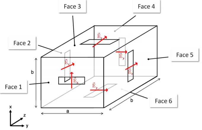
By supporting radiated slots on its faces, bulk geometries are able to radiate in a 4π steradians range which is well suited for indoor or urban communications where signals come from everywhere due to scattering introduced by the environment. Electromagnetic cavities appear as a judicious bulk structure because slots can be etched on each face (see fig. 1). Furthermore, slot locations and orientations can be chosen in an appropriate way according to the desired performances. In fact, rectangular slots set a linear polarization as indicated by
arrows in fig. 1, so the whole structure can radiate up to three orthogonal polarizations in order to decrease fading effects, for example. Since slots located on different faces have different main directions of propagation, radiation diversity can be achieved. In fact, this property, combined or not with the property of polarization, can be used to decrease the correlation between signals received or transmitted by each slot, and so to enhance the diversity gain.
Fig. 1 - Cavity and slots with electric field orientations
B. Design considerations
Working frequencies of such structures are determined by two resonance phenomena. The first one is due to the modes resonating inside the cavity and radiating through the slots. The second one is the slot’s own resonance. So, a feeding system, like a coaxial probe for example, can feed either cavity modes or the slots directly depending on its geometry and location. This dual resonance behavior can be used in order to manage the frequency bandwidth of the total structure. In fact, a typical value for a cavity bandwidth is about 2% whereas for a slot it is about 5% (for L- and C-bands). Depending on the desired bandwidth, it is possible to only use slot resonance, cavity resonance or both combined. This dual resonance behavior has been used to increase the frequency bandwidth up to 12% of the antenna presented in [7]. Furthermore, these two resonance frequencies are not necessarily identical. Thus, dual band applications can be investigated.
Slot and cavity resonance frequencies are determined by their geometry and size. Slots resonate as a multiple of λ/2 and the cavity resonance frequency is determined by the
expression: 2 1 2 2 2 2 2 2 + + = l p b n a m c
fmnp with c the light velocity, a, b, l the cavity sizes
and m, n, p the modal indexes. However, these two geometries disturb fields established in each resonator which results in frequency shifting. For the half-wavelength slots, two frequency shifts occur. The first one is due to the non infinite ground plane inevitably limited by the cavity size. The second one appears with the coupling between slots. In fact, this coupling can occur between slots etched on adjacent faces like slots on faces 1 and 3 or between slots etched on opposite faces like slots on faces 2 and 5. However, if slot field orientations are orthogonal, the coupling can be neglected like slots etched on faces 1 and 2 or on faces 1 and 4 for example. Furthermore, depending on their locations, slots can have a reactive effect on some cavity modes. This influence can be quantified by calculating the input admittance of the cavity through the slot, as defined by Cockrell in [4].
After seeing the potential of the cavity and radiating slots as a solution of antenna diversity systems, a practical antenna including its feeding access is now presented. Instead of having many antennas to produce diversity, the structure is designed in order to be used alone as an antenna diversity system itself.
III. THREE-PORT ANTENNA
A. Design
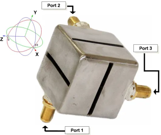
The proposed structure consists of a cavity on which three rectangular slots are etched (see fig. 2). Each slot radiates in a different direction than its neighbors and with an orthogonal polarization. So signals received or transmitted by each slot are uncorrelated. The structure is fed by three probes. Depending on its location, each probe can feed one cavity mode or the slot directly or both. Since each mode is coupled to only one slot, the power from each input port radiates through only one slot. As the modes are orthogonal, the coupling between each port is very low.
Such a cavity has been designed for Wi-Fi applications. In order to provide three access points at 5.25 GHz, the cavity is cubic. To maximize the cavity compactness, slot length has been increased up to the limit forced by the cube face length. In this configuration, cavity and slots resonate at the same frequency.
Fig. 2 - Cavity with electric field polarization (Slot Length = 28.6 mm, Cube Side = 30.3 mm, Probe
Length = 16 mm) B. Results
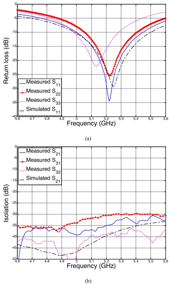
The antenna has been simulated with CST Microwave Studio and built. Fig. 3 shows the simulated and measured return losses and isolation between antenna ports. A 50 Ω impedance matching is achieved around 5.25 GHz (Fig. 3(a)). The frequency bandwidth in simulation is about 9.5% whereas in measurement, bandwidths are from about 5.8% (for S33) up to 8.6%
(for S11). Return losses are not strictly identical because of a lake of precision on probe
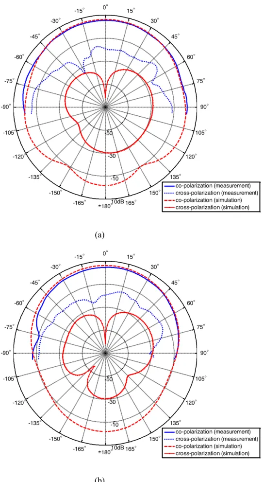
locations inside the cube. On Fig. 3(b), it can be observed that the antenna exhibits isolation greater than 30 dB. Fig. 4 compares the measurement and the simulation of the radiation pattern of the slot fed by the port 1 (Fig. 2). Radiation patterns are drawn according to the coordinate system presented in Fig. 2. The main electric field is along φ (co-polarization patterns) and the cross-polarization is along θ. Measurements have been conducted only in a half plane [-90°:+90°]. One can observed a peak gain of 6.2 dB in simulation and 5 dB in measurement at θ = 0° and φ = 0°. This difference can be explained by the fact that the
simulation does not take into account the metallic losses. Also, as usual, the cross polarization is higher in measurement than in simulation.
4.6 4.7 4.8 4.9 5 5.1 5.2 5.3 5.4 5.5 5.6 -40 -35 -30 -25 -20 -15 -10 -5 0
Frequency (GHz)
Retu
rn
los
s
(
dB
)
Measured S 11 Measured S 22 Measured S 33 Simulated S 11 (a) 4.6 4.7 4.8 4.9 5 5.1 5.2 5.3 5.4 5.5 5.6 -50 -45 -40 -35 -30 -25 -20 -15 -10 -5 0Frequency (GHz)
Is
ol
at
ion
(
dB
)
Measured S 21 Measured S 31 Measured S 32 Simulated S 21 (b)0° 15° 30° 45° 60° 75° 90° 105° 120° 135° 150° 165° ±180° -165° -150° -135° -120° -105° -90° -75° -60° -45° -30° -15° -50 -30 -10 10dB co-polarization (measurement) cross-polarization (measurement) co-polarization (simulation) cross-polarization (simulation) (a) 0° 15° 30° 45° 60° 75° 90° 105° 120° 135° 150° 165° ±180° -165° -150° -135° -120° -105° -90° -75° -60° -45° -30° -15° -50 -30 -10 10dB co-polarization (measurement) cross-polarization (measurement) co-polarization (simulation) cross-polarization (simulation) (b)
C. Diversity performances
The envelope correlation ρe provides a measure of antenna diversity performances. The
lower the correlation, the better the diversity performances. This coefficient is defined as in [1]:
(
)
(
)
∫
(
)
∫
∫
Ω Ω ΩΩ
+
Ω
+
Ω
+
=
d
p
E
E
p
E
XE
d
p
E
E
p
E
XE
d
p
E
E
p
E
XE
e φ φ φ θ θ θ φ φ φ θ θ θ φ φ φ θ θ θρ
* 2 2 * 2 2 * 1 1 * 1 1 2 * 2 1 * 2 1 , (1)where E1θ(Ω), E1φ (Ω), E2θ(Ω), E2φ (Ω) are complex electric fields along φ and θ radiated by the
antenna fed by two different ports. The angle Ω is defined by θ [0:π] in elevation and φ [0:2π] in azimuth. pθ(Ω) and pφ (Ω) are the Angle-of-Arrival (AoA) distributions of incoming waves.
The parameter X is the cross-polarization discrimination (XPD) of the incident field and is defined as XPD = Sθ/Sφ (where Sθ and Sφ represent the average power along the spherical
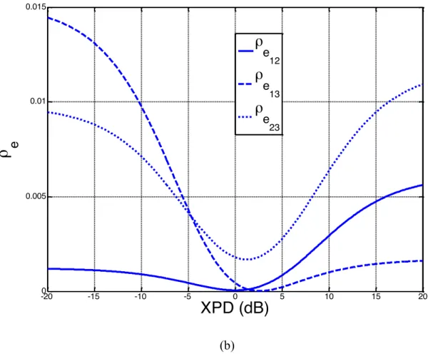
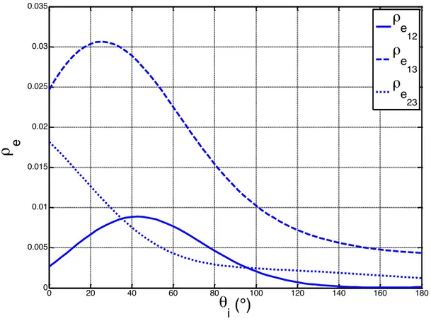
coordinates θ and φ). Fig. 5 presents envelope correlations between patterns of each input port and are calculated from simulated (a) and measured (b) radiation patterns (antenna radiation pattern measurements have been conducted in a 4π steradians range in a near-field anechoic chamber). The AoA distribution is supposed uniform. Results show that the worst envelope correlation is for XPD = +/- 20 dB and is always less than 0.0018 from simulated patterns and less than 0.015 from measured patterns. Even if there is a ratio of about 10 between simulation and measurement, the envelope correlation is still very low. In order to take into account a more realistic angular distribution, Figure 6 presents the envelope correlation (for XPD = -20 dB) from measured radiation pattern using a uniform distribution along φ and normal along θ. This distribution has been used in [9]-[11] and was determined from measurements in [12]. This can be expressed as:
(
)
(
)
(
)
−
−
−
=
=
2 2 22
2
/
exp
2
1
,
,
θ θ φ θσ
θ
π
θ
πσ
φ
θ
φ
θ
ip
p
, (2)where θi is the mean of the direction of incoming waves (according to the coordinate system
in Fig. 2) and σθ = 10° is their standard deviation. The worst envelope correlation is for ρe13 at
θi =25° and is less than 0.035. These results indicate that this kind of structure is well suited
for an antenna diversity communication scheme since an effective diversity action can be obtained as long as ρe is less than 0.7 [13].
-200 -15 -10 -5 0 5 10 15 20 0.2 0.4 0.6 0.8 1 1.2 1.4 1.6 1.8x 10 -3
ρ
eXPD (dB)
ρ
e 12ρ
e 13ρ
e 23 (a)-200 -15 -10 -5 0 5 10 15 20 0.005 0.01 0.015
ρ
eXPD (dB)
ρ
e 12ρ
e 13ρ
e 23 (b)0 20 40 60 80 100 120 140 160 180 0 0.005 0.01 0.015 0.02 0.025 0.03 0.035
ρ
eθ
i(°)
ρ
e 12ρ
e 13ρ
e 23Figure 6- Envelope correlation from measured radiation patterns with XPD=-20dB and σθ=10°
IV. CONCLUSION
The concept of electromagnetic cavities and radiated slots for antenna diversity communications has been discussed. A three-port antenna which presents a high isolation between the input ports has been presented. Since three uncorrelated channels are available, this structure can be used in spatial multiplexing MIMO systems. With a global approach where capabilities of rectangular cavities etched by slots have been underlined, the study of the proposed antenna proves that this kind of structures is well-suited for diversity communication schemes.
V. REFERENCES
[1] R.G. Vaughan and J.B. Anderson, “Antenna diversity in mobile communications”,
[2] M.A. Andrews, P.P. Mitra and R. Carvalho, “Tripling the capacity of wireless communications using electromagnetic polarization,” Nature, vol. 409, pp. 316–318, Jan. 2001
[3] C.-Y. Chiu, J.-B. Yan and R.D. Murch, “Compact three-port orthogonally polarized MIMO antennas”, IEEE Antennas and wireless propagation letters, vol. 6, pp. 619-622, Dec. 2007
[4] J.B. Andersen and B.N. Getu, “The MIMO cube—A compact MIMO antenna,” Proc. 5th
Int. Symp.Wireless Personal Multimedia Communications, vol. 1, pp. 112–114, Oct. 2002
[5] B. N. Getu and J. B. Andersen, “The MIMO cube—A compact MIMO antenna,” IEEE
Trans. Wireless Commun., vol. 4, no. 3, pp. 1136–1141, May 2005
[6] A.T. Adams, “Flushed mounted rectangular cavity slot antennas – theory and design”,
IEEE Trans. Antennas and Propagation, vol. 15, pp. 342-351, May 1967
[7] J. Sarrazin, Y. Mahé, S. Avrillon and S. Toutain, “On the bandwidth enhancement of a multipolarization and reconfigurable pattern antenna for adaptive MIMO systems”, Antennas
and Propagation Symposium, Honolulu, 10-15 June 2007
[8] C.R. Cockrell, “The input admittance of the rectangular cavity-backed slot antenna”,
IEEE Trans. Antennas and Propagation, vol. 24, pp. 288-294, May 1976
[9] M.K. Özdemir, H. Arslan and E. Arvas, “On the correlation analysis of antennas in adaptive MIMO systems with 3-D multipath scattering”, IEEE Wireless Communications and
Networking Conference, vol. 1, pp. 295-299, March 2004
[10] Y. Ebine and Y. Yamada, “A vehicular-mounted vertical space diversity antenna for a land mobile radio”, IEEE Trans. Veh. Technolo., vol. 40, n°2, pp. 420-425, May 1991
[11] K. Tsunekawa and K. Kagoshima, “Analysis of a correlation coefficient of built-in diversity antennas for a portable telephone”, IEEE Antennas and Propagation Symposium, vol. 1, Dallas, TX, pp. 543-546, May 1990
[12] F. Adachi, M.T. Feeney, A.G. Williamson and J.D. Parsons, “Crosscorrelation between the envelopes of 900 MHz signals received at a mobile radio base station site”, Proc.
Inst. Elect. Eng., vol. 133, n°6, pp. 506-512, Oct. 1986
[13] J.N. Pierce and S. Stein, “Multiple diversity with nonindependant fading”, Proc. IRE, vol. 48, pp. 89-104, Jan. 1960