Compatibilization of immiscible polymer blends (PV/PVDF) by the addition
of a third polymer (PMMA): analysis of phase morphology and mechanical
properties
Noureddin Moussaif, Robert Jérôme
Center for Education and Research on Macromolecules (CERM), University of Liège, Institute of Chemistry, B6, Sart-Tilman, 4000 Liège, Belgium
Abstract
Compatibilization of the immiscible polycarbonate (PC)/polyvinylidenefluoride (PVDF) pair by a third homopolymer, i.e. polymethylmethacrylate (PMMA), was studied in relation to phase morphology and mechanical properties of the polyblends. Scanning electron microscopy showed a more regular and finer phase dispersion when the original PMMA content in PVDF exceeded 20 wt.%. The premixing of PVDF with ca. 40 wt.% PMMA also had a beneficial effect on mechanical properties, such as ultimate tensile strength, elongation at break, and notched impact strength. All these experimental results are consistent with the interfacial activity of PMMA in the PC/PVDF blends.
Keywords: Polymer blends; Polymethylmethacrylate; Polycarbonate
1. Introduction
Most polymer blends of commercial interest are multiphase materials as a result of the thermodynamic immiscibility of the constitutive components. The usually high immiscibility of polymer pairs results in gross phase separation and poor interfacial adhesion, which requires these polyblends to be compatibilized. This situation explains why interface engineering has been a major research topic in the polymer blend area for the last decade [1,2].
The most general strategy for improving the compatibility of immiscible polymers is the use of block or graft copolymers, whose one block is identical or at least miscible with one blend component, and the second constituent block is identical to/or miscible with the second blend component. Depending on the molecular parameters, this type of copolymers exhibit interfacial activity and reinforce the interface [3—19].
The implementation of "reactive blending" has been a major progress in the blends compatibilization, as the in situ formation of the polymeric surfactant may significantly improve the economy of the blends processing [20—24]. In an alternative strategy, Fleischer and Koberstein have reported on the effective compatibilization of immisciblepolymers as result of non covalent although strong (e.g. ionic) interactions between the constitutive polymers through the interface [25].
Hobbs et al. have observed a substantial compatibilization upon the addition of a third polymeric component immiscible with each of the blended polymers but selected for a relatively low interfacial tension with each of them. The criteria for compatibilization are spreading coefficients so that the additive is selectively localized at the interface of the original two-phase polyblend [26]. As an extreme case of this third strategy, the
compatibilization agent is completely miscible with the two components of the binary blend [27].
The major limitation of the first strategy is the very limited availability of block copolymers, that are anyway costly materials. The reactive blending can only be contemplated when the polymers to be blended can be modified by functional groups mutually reactive and stable under the processing conditions [23,24,28]. These prerequisites are not fulfilled in the specific case of polycarbonate (PC) and polyvinylidenefluoride (PVDF) blends, as no parent block or graft copolymer can be made available, and the appropriate functionalization of these polymers is not straightforward. In this work, polymethylmethacrylate (PMMA) has been considered as a potential compatibilizer for the PC/ PVDF polyblends, as PMMA is known to be miscible with PVDF [29—31] and compatible with PC [32-34].
In the extreme, PMMA might behave as a common "solvent" for PC and PVDF in the melt.
In a previous article, the ability of PMMA to decrease the PC/PVDF interfacial tension and to improve the PC/PVDF interfacial adhesion has been investigated [35]. Briefly, the PC/PVDF interfacial adhesion is steadily
improved by the premixing of PVDF with increasing amounts of PMMA. This improvement tends however to level off when the PMMA concentration in PVDF exceeds 35 wt.% PMMA. In parallel, the interfacial tension between melted PC and PVDF is decreased down to a plateau value when PVDF is premixed with ca. 40 wt.% PMMA. These observations are thus consistent with the interfacial activity of PMMA in PC/ PVDF blends. This article deals with the beneficial effect that PMMA can have on the phase morphology and the mechanical properties of these polyblends.
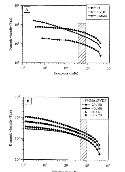
Fig. 1. (A) Frequency dependence of the dynamic viscosity at 235°C for PC, PVDF and PMMA. (B) Frequency dependence of the dynamic viscosity at 235°C for PVDF/PMMA blends.
2. Experimental
The main characteristics of the polymers used in this study are listed in Table 1. Blends were prepared by mixing the polymeric components in a Brabender mixing chamber (Plasti-corder) at 235°C, for 8 min, the rotation speed being 50 rpm. PC was first added and melted under mixing for 3 min, followed by the addition of PMMA and PVDF. Samples of PC, PVDF/PMMA and PC/PMMA/PVDF blends were prepared by compression molding at 220°C for 5 min and then quenched at room temperature still under pressure. The polymers were previously dried overnight in a vacuum oven at 120°C for PC and 70°C for PMMA.
Stress—strain curves were recorded with an Intsrom universal tensile tester (model DY 24) at a tensile rate of 20 mm min-, and yield strength (σy, MPa), ultimate tensile strength (σb, MPa) and elongation at break (σb, %) were
reported as average values for at least five samples.
Charpy impact tests were carried out at room temperature with a 20 J hammer and notched samples. The impact energy was the average value for five samples of 50 mm length, 6 mm width, and 2 mm thickness, the notch depth being 0.35 mm.
Samples for tensile and impact testing were cut out from2 mm thick plates prepared by compression molding at 220°C.
A Jeol JSM-840 A Scanning Electron Microscope (SEM) was used to observe fracture surfaces prepared at the liquid nitrogen temperature.
Image analysis was carried out using a Sun Sparc 10 working station equipped with a visilog noenis software (France).
Table 1: Main characteristics and origin of the polymers used in this study Polymers Abbreviation Commercial
designation
Source Molecular weight Mw(10-3)
MwMn Tgb (°C) Density (g cm-3)
230 the 80/20°C Polycarbonate PC Makrolon 3103 Bayer 58a 1.7a 150 1.09
Polymethylmethacrylate PMMA Diakon ICI 60a 1.6a 118 1.08 Polyvinylidenefluoride PVDF Solef x 10N Solvay 125 1.8 -45 1.7
a Determined by SEC with a polystyrene calibration. b Determined by dynamic mechanical analysis (DMA) at 1 Hz.
Table 2: Viscosity and viscosity ratio for PC, PVDF, PMMA and homogeneous PVDF-PMMA blends of various compositions (235°C, 60 s)
Viscosity (Pa s) Viscosity ratio nPC/N (PMMA/PVDF)
PC 4020 - PVDF 2600 1.55 PMMA 950 - 20 PMMA/80 PVDF 2170 1.85 40 PMMA/60 PVDF 1620 2.48 60 PMMA/40 PVDF 1100 3.65 80 PMMA/20 PVDF 1140 3.53
3. Results and discussion 3.1. Effect of blend composition
The frequency dependence of the dynamic viscosity at 235°C for PC, PVDF and PMMA is shown in Fig. 1(A). According to Cox and Merz [36], these plots are equivalent to shear viscosity versus shear rate plots. The polycarbonate viscosity is high and essentially independent of frequency until 50 rad s-1. In contrast, the viscosity of PVDF decreases upon increasing the frequency, so that the viscosity ratio for these two polymers at 235°C changes with the shear rate. In the whole frequency range (0.5—500 rad s-1), PMMA is much less viscous than PC and PVDF at 235°C, which explains that the PVDF viscosity decreases with the PMMA content (at least until 60 wt.% PMMA) at high shear rates (50—100 s-1) and 235°C (Fig. 1(B)).
The viscosity and viscosity ratio for PC, PVDF, PMMA and (PVDF-PMMA) blends at 235°C and a shear rate of 60 s-1 are listed in Table 2.
occurs at a composition that depends on the viscosity ratio (Eq.
(1)).
where η1 and η2 are the viscosities for the phases 1 and 2, respectively; θ1 and θ2 are the volume fractions of
these phases at the phase inversion.
For the type of mixing chamber and the mixing rate (50 rpm) used in this study, the maximum shear rate was estimated at approximately 60s-1. From Eq. (1) and the data in Table 1, the phase inversion (thus the dual-phase continuity) should occur at θPC = 0.48 for the PC/PVDF blends and at θPC in the range of 0.49—0.54 when the
PMMA content in PVDF is increased from 20 to 80 wt.%. (Table 3).
Jordhamo et al. have however questioned the validity of the semi-empirical Wu's equation [38], and proposed an exponent of 1 instead of 0.29 to the viscosity ratio. This disagreement is of course as important as the viscosity ratio is different from 1. In this study, as the PC/PVDF viscosity ratio at 235°C does not change too much with the PMMA content in PVDF (maximum by 2.3; Table 2), the phase inversion is predicted to occur in a comparable composition range for all the PC/(PVDF/PMMA) blends, whatever the equation used (Table 3). The SEM observation of fracture surfaces is a qualitative way to confirm the phase morphology of polyblends. Figs. 2(a)-(d) and 3(a)-(h) illustrate the fracture surfaces for PC/PVDF blends and for PC/(PVDF-PMMA) blendscontaining 20, 40 60, and 80 wt.% PC. The phase morphology changes from dispersed phases of PC (Fig. 2(a)) to an apparently co-continuous morphology (Figs 2(b) and (c)) as the PC content is increased at the expense of the (PVDF/ PMMA) component. Although SEM provides a 2-D observation of a 3-D situation, the phase inversion reasonably seems to occur between 40 and 60 wt.% PC (i.e. in the 43—65 vol% PC range). PC definitely forms the continuous phase of a dispersed type morphology when used at 80 wt.%. In order to confirm this preliminary investigation of the phase morphology, selective extractions of one polymeric component by a suitable solvent were carried out. In the case of complete extraction, the parent phase is continuous. If the original sample is not at all disintegrated as result of the complete extraction of one phase, the two phases are co-continuous. When the selective extraction of one phase remains uncomplete, this phase is at least partly
dispersed [39,40]. In the specific case of the PC/PVDF and PC/(PVDF—P MMA) blends, PC and PMMA can be selectively dissolved by CHCl3. The major observations are reported in Table 4 and Table 5 for the two series of
blends under consideration. The 20/80 and 80/20 PC/PVDF blends have a typical phase dispersed morphology. Indeed, the 20 wt.% PC of the former blend cannot be extracted at all, whereas the 20 wt.% PVDF are collected as so small fragments upon dissolution of PC in the latter blend that their separation from the CHCl3 solution is
quite a problem. The co-continuity of the phases in the 40/60 and 60/40 PC/PVDF blends is close to 100% as the PC extraction is complete within the limits of inaccuracy because of contamination of the extraction solution by faint PVDF fragments. Thepremixing of PVDF with increasing amounts of PMMA does not basically change the phase morphology of the co-continuous 40/60 and 60/40 PC/PVDF blends, as the (PC + PMMA) extraction is complete within the limits of experimental errors (Table 5). As a rule, the wt.% nonex-tracted polymer slightly exceeds the theoretical PVDF content, which more likely indicates that a small part of PMMA is not extracted from PVDF. For the 60/40 (80— 20) PC/(PVDF—PMMA) blend, the residual solid fraction is much smaller than expected as a result of the very problematic separation of the solid residue from the CHCl3 solution.
Table 3: Composition at phase inversion (vol. Fraction PC)
Blends Spc PC/PVDF 0.48 PC/(80 PVDF-20 PMMA) 0.49 PMMA PC/(60 PVDF-40 PMMA) 0.51 PC/(40 PVDF-60 PMMA) 0.54 PC/(20 PVDF-80 PMMA) 0.54
Table 4: Phase morphology of the PC/PVDF blends as analyzed by CHCI3 extraction of PC PC/PVDF Extraction time (days) Shape after extraction Wt. % extracted PCa
Solvent aspect Conclusions
20/80 15 Intact 0(20) Transparent Dispersed morphology 40/60 15 Partially
disintegrated
40.5 (40) Cloudy solution Co-continuous morphology 60/40 15 Partially
disintegrated
62 (60) Cloudy solution Co-continuous morphology
80/20 15 Totally disintegrated 96 (80) Very cloudy solution Dispersed morpholoty
a Theoretical values in parenthesis.
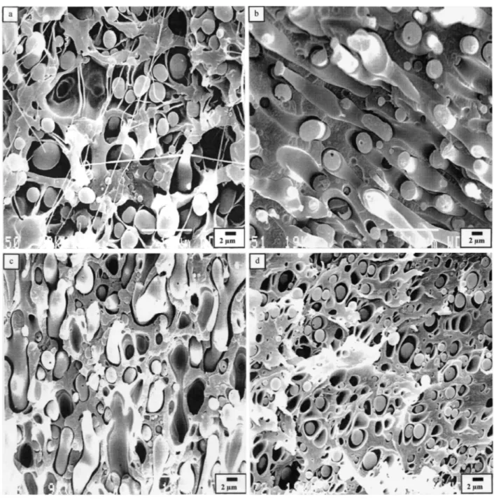
Fig. 2. Micrographs of fracture surfaces for different blend compositions of PC/PVDF (wt/wt.%), (a) 20/80, (b) 40/60, (c) 60/40 and (d) /80/20
Fig. 2 shows that the dispersed domains are smaller in size when PVDF is the dispersed phase rather than PC. This observation may be explained, at least partly, by the difference in the melt viscosity of these two
components, as the more viscous PC (dispersed) phase is more resistent to break-up than the PVDF one during melt mixing at 235°C [41].
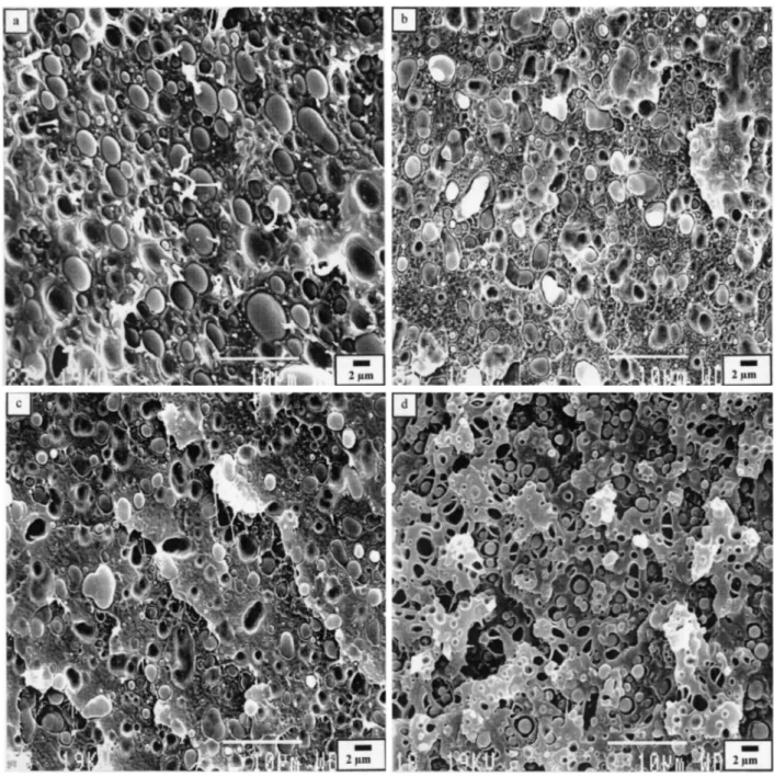
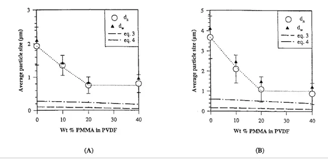
The neat dispersed PC/PVDF blends show a phase morphology typical of highly immiscible polymers, with very large, coarse and irregular dispersed domains (Figs. 2(a) and (d)). More regular and finer dispersion is observed, when 10 wt % PMMA is premixed with PVDF in the 20/80 and 80/20 PC/ PVDF blends. Indeed, the average particle size is then reduced up to four times (see Figs. 3(a)-(f)). Typical emulsification curves are shown in Fig. 4 for the 20/80 and 80/20 PC/PVDF blends added with PMMA.
It is worth comparing the average diameter observed for the dispersed domains to predictions based on various models. For newtonian polymers in a simple shear flow,particle breakup is expected to occur when the shear forces that deform the droplets exceeds the interfacial forces. On the basis of this force balance, Taylor [42— 44] proposed to calculate the size of stable drops in dilute newtonian system by Eq. (2). Several authors have also discussed the effect that the viscosity ratio can have on the phase morphology of melt processed binary blends. In the case of polyamide/rubber blends, Wu [45] observed that the smallest particles were formed when the viscosity of the constitutive polymers were comparable (λ = 1). He also reported a good agreement between the final particlediameter and values calculated from Eq. (3) over a wide range of polymer viscosities and interfacial tensions for low contents of dispersed phases (<15%). As particle coalescence was not taken into account in Eqs. (2) and (3), the predicted diameter must be considered as the lower limit value. Serpe et al. [46] further
developed this type of equation by using the blend viscosity rather than the matrix viscosity and by considering a term of composition, thus coalescence effects (Eq. (4)). Using this modified viscosity ratio, Serpe confirmed Wu's equation for PE/PA6 blends.
with the λ exponent = + 0.84 for λ > 1 and -0.84 for λ < 1
where, γ1,2 is the interfacial tension between components 1 and 2, ηd is the viscosity of the dispersed phase, ηm is
the viscosity of the matrix , ηb is the viscosity of the blend, λ is the viscosity ratio (= ηd/ηm) φ volume fraction of
the dispersed phase (φd) and the matrix (φm) and γ is the shear rate.
The particle diameters were calculated from Eqs. (3) and (4) and compared to the experimental values in Fig. 4. As previously mentioned and in agreement with Refs. [47,48] the shear mixing rate was estimated at 60 s-1, and the related viscosities and viscosity ratios are available in Table 2. The interfacial tensions, γ1,2 have been
measured by the imbedded fiber retraction method [49] as reported in Table 6.
The particle diameters calculated by Wu's equation (Eq. (3)) are much smaller than the experimental values, consistently with the fact that particle coalescence is not considered in Eq. (3) and with a non negligible content of the dispersed polymer (20 wt.%). Except for the neat PC/ PVDF blends, the particle diameters calculated by the Serpe equation are in better agreement with experimental values, particularly in Fig. 4(B). The poor fitting of experimental theoretical data might, at least partly, result from coalescence during compression molding at 220°C for 5 min [50—52]. Nevertheless, Eqs. (3) and (4) cannot predict the sharp decrease in the particle diameter which occurs upon addition of small amounts of PMMA (20 wt.%) to PVDF, as the viscosity data are not changed very significantly. This observation more likely emphasizes the beneficial effect of PMMA, which decreases γ1,2 to the point where the particles coalescence is significantly slowed down and in a finer phase
Table 5: Phase morphology of the PC/(PVDF-PMMA) blends as analyzed by CHCI3 extraction of PMMA and PC PC/(PVDF-PMMA) Extraction time (days) Shape after extraction Wt. % Nonextracted polymer (PVDF)a
Solvent aspect Conclusions
40/60 (80-20) 15 Partially disintegrated
52 (48) Cloudy solution Co-continuous morphology
40/60 (60-40) 15 Partially disintegrated
38.5 (36) Cloudy solution Co-continuous morphology
40/60 (40-60) 15 Partially disintegrated
25 (24) Cloudy solution Co-continuous morphology
40/60 (20-80) 15 Partially disintegrated
13(12) Cloudy solution Co-continuous morphology
60/40 (80-20) 15 Partially disintegrated
24 (32) Cloudy solution Co-continuous morphology
60/40 (60-40) 15 Partially disintegrated
25.5 (24) Cloudy solution Co-continuous morphology
60/40 (40-60) 15 Partially disintegrated
17.5 (16) Cloudy solution Co-continuous morphology
60/40 (20-80) 15 Partially disintegrated
8.5 (8.0) Cloudy solution Co-continuous morphology
a
Theoretical values in parenthesis.
Table 6: Interfacial tension between PC and PMMA/PVDF blends of different compositions at 220°C Matrix γπ2 (dyn/cm-1)
PVDF 4.5 ± 0.6
20 PMMA / 80 PVDF 3.0 ± 0.5 40 PMMA / 60 PVDF 1.2 ± 0.5
Fig. 3. Micrographs of fracture surfaces for different blend compositions of PC/(PMMA-PVDF) blends of various compositions, (a) 20/80 PC/(10PMMA-90PVDF), (b) 20/80 PC/(20PMMA-80PVDF), (c) 20/80 PC/(40PMMA-60PVDF), (d) 80/20 PC/(10PMMA-90PVDF), (e) 80/20 PC/(20PMMA-80PVDF), (f) 80/20 PC/(40PMMA-60PVDF), (g) 40/60 PC/(40PMMA-60PVDF), (h) 60/40 PC/(40PMMA-60PVDF).
Fig. 4. Average particle diameter versus the PMMA content of the mixed PVDF/PMMA phase, for (A) the 80/20 PC/(PVDF-PAMMA) blends (λ < 1). (B) the 20/80 PC/(PVDF-PAMMA) blends (λ > 1).
3.2. Mechanical properties 3.2.1. Neat PC/PVDF blends
In non compatibilized blends of immiscible polymers, the interfacial adhesion is usually not strong enough for stress to be efficiently transferred from one phase to another oneduring yielding and/or fracture, thus resulting in poor mechanical properties. A previous article has reported that the PC/PVDF interfacial adhesion was improved by the addition of PMMA, that concentrated preferably in the PVDF rich phase, but also migrated to the
PVDF/PC interface [35]. Measurement of the tensile properties of the PC/ PVDF blends is another way to estimate how far interfacial adhesion, and thus the compatibilization effect, are improved by the addition of PMMA to PVDF. Tensile properties, particularly the elongation at break, εb, are indeed very sensitive to the
strength of the interface, and they are routinely measured to evaluate the efficiency of compatibi-lization techniques [53,54]. The ultimate mechanical properties (σb, εb) and the yield strength (σy) of PC/PVDF blends
are reported in Figs. 5(A) and (B).
Fig. 5(A) shows that the elongation at break, εb, is dramatically decreased in the whole composition range of the
PC/ PVDF blends compared to neat PC and PVDF. The dependence of the yield and ultimate tensile strength on the blend composition also shows a negative deviation with respect to the additivity rule (Fig. 5(B)). This general observation is consistent with a weak interfacial adhesion in the PC/PVDF blends.
3.2.2. PC/(PVDF/PMMA) ternary blends
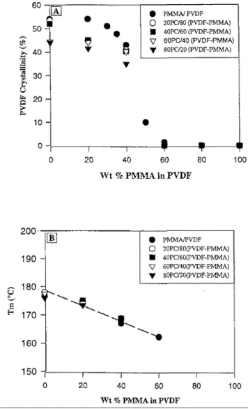
In parallel to the investigation of the compatibilization activity of PMMA in the PC/PVDF binary blends, it is desirable to analyze the main physico-mechanical properties of the PVDF/PMMA blends. The degree of crystallinity and the melting temperature (Tm) of PVDF were measured by DSC as shown in Figs. 6(A) and (B).
An S-shaped curve is a good description for the dependence of the PVDF crys-tallinity on the PMMA content (Fig. 6(A)). Beyond approximately 60 wt % PMMA in PVDF, all these blends are amorphous. In contrast, the melting temperature of PVDF linearly decreases when the PMMA content is increased up to 60 wt.%. Figs. 6(A) and (B) also confirm that the melting properties of PVDF in the PVDF/PMMA blends are not significantly modified by mixing these blends with PC, except for a smaller crystallinity at low PMMA contents (<40 wt.%) (Fig. 6(A)).
Fig. 7(A) shows how the elongation at break depends on the PMMA content in the PMMA/PVDF binary blends. Blends containing 20—40 wt % PMMA are ductile, whereas PMMA and PMMA/PVDF blends containing 60 wt.% PMMA and more are typically brittle.
Fig. 7(B) illustrates the dependence of the ultimate and yield strengths of the PMMA/PVDF blends on the blend composition. These data are in a qualitative agreement with observations reported by Noland et al. [55]. In order to explain the main characteristic features of Fig. 7, it is worth noting that the glass transition temperature (Tg)
approximately 10 wt.% PMMA contents. Thus when the PVDF/ PMMA blends become predominantly amorphous [56—58].
Therefore, it is not surprising that both the yield and the ultimate tensile strengths start to decrease when PMMA is added with PVDF. This is the typical response when a liquid or a rubbery diluent (PVDF) is added to a glassy polymer (PMMA). However, tensile strengths pass through a minimum and then increase on further addition of PMMA. This behavior is consistent with a strengthening effect caused by crystallization of PVDF and,
vitrification of the amorphous phase. Conversely, the elongation at break is very small for glassy PMMA and polyblends containing up to 40 wt.% PVDF. Upon further addition of PVDF, Tg falls in the range of the testing
temperature and εb increases rapidly. However, the tendency is reversed when PVDF starts to crystallize.
Fig. 5. (A) Dependence of the elongation at break on the PC content for the PC/PVDF blends. (B) Dependence of the yield and ultimate tensile strength on the PC content for the PC/PVDF blends
Tensile properties of 20 PC/80 (PMMA-PVDF) blends versus the PMMA content in PVDF are shown in Figs. 8(A) and (B). Upon dispersion of 20wt.% PC, the tensile strengths at the yield point and at break for PVDF (Fig. 7(B)) merge to a unique value (45 MPa; Fig. 8(A)). However, when PVDF is premixed with PMMA, 20 wt.% PC have essentially no effect on the tensile strength of the PVDF/PMMA binary blends (comparison of Figs. 7(B) and 8(A)), which is an evidence for the PC/PVDF compatibili-zation by PMMA. Similarly, 20 wt.% PC make PVDF completely brittle (Fig. 8(B)). When PVDF is mixed with more than 20 wt.% PMMA, the elongation at break is remarkably increased, consistently with an improved inter-facial adhesion. Beyond 40 wt.% PMMA in PVDF, a transition from a ductile to a brittle-like behavior is observed as was the case for the neat PVDF/PMMA blends (that form the matrix of the 20 PC/80 (PVDF/PMMA) blends) in this composition range.
In the case of the reverse composition for the ternary blends (80PC/20(PVDF—PMMA)), (Fig. 9(B)) brittleness is observed to dominate in absence of PMMA. Addition of 20 wt.% PMMA to PVDF remarkably increases the
elongation at break, once again in line with an improved inter-facial adhesion.
Although the ductile behavior persists in the whole PVDF/PMMA composition range, some decrease is observed when the PMMA content in PVDF is 50 wt.% and higher, thus when the dispersed phase becomes amorphous and glassy. Although slightly improved by the addition of PMMA, the tensile strength (σy and σb) of these
ternary blends (Fig. 9(A)) is basically independent of the PMMA content of the dispersed phase.
As a rule, the same qualitative observations are reported for ternary blends of a co-continuous two-phase morphology (Figs 10(A), (B) and 11(A), (B)) as for those with a dispersed phase morphology. In the absence of PMMA, the interface is weak and the ternary blends are brittle. The addition of 20 wt.% and more interestingly 40 wt.% PMMA to PVDF improves the ultimate mechanical properties of the 40/60 and 60/40 PC/(PVDF— PMMA) blends. The compati-bilization efficiency of PMMA in PC/PVDF blends is thus convincingly supported by the general improvement of the mechanical behavior, and the usually observed transition from brittle to ductile blends.
Fig. 6. (A) Crystallinity of PVDF versus the PMMA content in PVDF. (B). Melting temperature of PVDF versus the PMMA content in PVDF.
Fig. 7. (A) Elongation at break versus the PMMA content for PVDF/ PMMA blends. (B) Yield and ultimate tensile strengths versus the PMMA content for PVDF/PMMA blends.
Fig. 8. (A) Yield and ultimate tensile strengths versus the PMMA content in PVDF for the 20/80 PC/(PVDF-PMMA) blends. (B) Elongation at break versus the PMMA content in PVDF for the 20/80 PC/(PVDF-PC/(PVDF-PMMA) blends.
Fig. 9. (A) Yield ultimate tensile strengths versus the PMMA content in PVDF for the 80/20 PC/(PVDF-PMMA) blends. (B) Elongation at break versus the PMMA content in PVDF for the 80/20 PC/(PVDF-PMMA) blends.
3.3. Charpy impact strength properties
The Charpy impact strength confirms the brittleness of the PC/PVDF blends in the whole composition range (Fig. 12). Indeed, the ductility of PC (90 kJ m-2) and PVDF (65 kJ m-2) is rapidly lost when these two polymers are melt blended (less than 10kJm-2, except for the 80/20 PC/PVDF blend). Fig. 13 shows the notched Charpy impact strength for ternary blends PC/(PMMA—PVDF) of a dispersed phase morphology. The addition of PMMA, which is intrinsically brittle (impact strength = 5 kJ m-2), to the 80/20 PC/PVDF binary blend increases the impact strength particularly when 40 wt.% PMMA is mixed with PVDF. The same general curve is also observed for the reverse PC/PVDF composition (20/80), although the effect is comparatively faint. When PC is the matrix (80%), the addition of PMMA improves the impact strength whatever be the PVDF/PMMA
composition. An improvement in the interfacial adhesion between the dispersed phase and the PC matrix is thought to be responsible for this beneficial effect, as the intrinsic ductility of PVDF is lost when mixed with PMMA (Fig. 14). This explanation is supported by the observation by Kunori and Ceil [59] that the PC ductility is adversely affected by the addition of 2 wt.% PS as a result of the weak PC/PS interfacial adhesion and possibly of a coarser phase morphology.
When PVDF is the matrix (80 wt.%), the addition ofPMMA has no chance to improve the impact strength of the ternary blends (Fig. 13), as PVDF becomes rapidly brittle upon the addition of 20 wt.% PMMA (Fig. 14). The co-continuity in the 40/60 and 60/40 PC/(PVDF-PMMA) ternary blends (Fig. 15) does not basically change the situation observed in Fig. 13. The comparison would suggest that a randomly dispersed phase morphology is a favorable although not sufficient condition to impart toughness to a polymeric material [60]. Clearly the conclusions on the effect of PMMA on the PC/PVDF binary blends are at variance depending on the properties measured, i.e. tensile properties or Charpy impact strength. The origin for this discrepancy has to be found in the deformation speed, which is fast in the impact testing and comparatively slow when tensile properties are measured. The possible relaxation of the inclusions at low deformation speeds, can account for the plane strain permitting the failure ductility. At high speeds, this relaxation cannot occur leading to brittle failure in thick
samples [61].
The results reported in this article confirm that the addition of a two-phase polymer blend by a third polymer miscible to one blend component and compatible to the second one may be a valuable strategy for the blend compatibilization. Compared to the use of block or graft copolymers as interfacial agents, this strategy requires however a larger amount of the additive. This drawback may be largely compensated by the availability and the lower cost of a homopolymer (or random copolymer) compared to block or graft copolymers.
Fig. 10. (A) Yield and ultimate tensile strengths versus the PMMA content in PVDF for the 40/60 PC(PVDF-PMMA) blends. (B) Elongation at break versus the PMMA content in PVDF for the 40/60 PC/(PVDF-PC(PVDF-PMMA) blends.
Fig. 11. (A) Yield ultimate tensile strengths versus the PMMA content in PVDF for the 60/40 PC/(PVDF-PMMA) blends. (B) Elogngation at break versus the PMMA content in PVDF for the 60/40 PC/(PVDF-PC/(PVDF-PMMA) blends.
Fig. 13. Charpy impact strength versus the PMMA content in PVDF for PC/(PVDF-PMMA) blends.
Fig. 14. Charpy impact strength versus the PMMA content for PC/PMMA and PVDF/PMMA blends.
The basic assumption for explaining the compatibilization efficiency of PMMA in PC/PVDF blends is the migration of PMMA from the PVDF phase to the interface. The driving force for this migration may be identified by analogy with the well-known observation that the free surface of miscible blends is enriched with the component of the lower surface tension [62—64]. This phenomenon occurs provided that the free energy for setting up a composition gradient in the surface region is more than compensated by reducing the surface tension to a minimum. Quite similarly, the interfa-cial tension of PC/PVDF immiscible blends can be lowered by creating a PMMA/PVDF composition gradient on the PVDF side with accumulation of PMMA at the interface. The prerequisite is of course that the new PC/PMMA inter-facial tension is smaller than the original PC/PVDF one. So the energy gained in substituting favorable (enthalpic) interactions for unfavorable ones at the interface must be higher than the energy cost associated with the rupture of favorable interactions in the bulk of each phase.
This condition is fulfilled in the PC/(PVDF—PMMA) system, as e.g. the PC/PMMA interfacial tension (0.6 dyn cm-1) is smaller than the PC/PVDF one (4.5 dyn cm-1). Further, PMMA is compatible to PC, in contrast to PVDF which is highly immiscible to this component. The accumulation of PMMA at the PC/PVDF interface may have a favorable effect on the conformational entropy in the inter-facial region. Indeed, two immiscible polymers, such as PVDF and PC, have to minimize their mutual interpenetra-tion, and accordingly have a (more) collapsed conformation in the vicinity of the interface [65]. This is the primary cause for a weak interface in immiscible polymer blends. In case of substitution of PVDF by PMMA, conformations more favorable to molecular
interpenetrations across the interface might develop in line with the PC/PMMA compatibility and account for the strengthening of the interface.
ternary blends investigated by Hobbs et al. [26]. The only difference is the miscibility of two of the three components, thus one of the three interfacial tensions which is zero. As in this study, the interfacial tension between primary components (PC and PVDF) is higher than that between PC and PMMA, the spreading coefficient (given by γPC/PVDF -γPC/PMMA - γPVDF/PMMA = 3.9) is positive, which is indeed predictive of interfacial
activity.
Fig. 15. Charpy impact strength versus the PMMA content in PVDF for PC/(PVDF-PMMA) blends.
4. Conclusions
This work has confirmed that immiscible PC/PVDF polymer blends could be compatibilized by the addition of a third polymer, PMMA. This polymeric additive has been selected for miscibility with one phase (PVDF) and a lower interfacial tension with the second phase compared to the original PC/PVDF interface. The required amount of PMMA is however rather large (20—40 wt.% with respect to PVDF) which is not prohibitive owing to the large availability and low cost of PMMA. The blend compatibilization is supported by a finer phase dispersion and improved tensile properties including elongation at break. The Charpy impact testing, which assumes conditions of fastdeformation, does not systematically conclude much improved performances. This observation is not a negative evidence for the blends compatibilization, but might merely indicate that PC is not an ideal toughening agent for PVDF (or PVDF/PMMA one phase blends) and viceversa.
Acknowledgements
The authors are very grateful to the "Services Fédéraux des Affaires Scientifiques, Techniques et Culturelles" in the framework of the "Poles d'Attraction Interuniversitaires": PAI 4/11. N.M. is indebted to the "Ministère de l'Enseignement Suρerieur de la Formation des Cadres et de la Recherche Scientifique du Maroc" for a fellowship. The authors also wish to thank Mr C. Pagnoulle, Dr I. Luzi-nov and Dr Ph Maréchal for useful discussions, and Mrs S. Blacher for her collaboration in image analysis.
References
[1] Teyssie Ph. Macromol. Chem Macromol Symp 1988;22:82. [2] Xanthos M. Polym Eng Sci 1988;28:392.
[3] Fayt R, Jerome R, Teyssié Ph. J Polym Sci Polym Phys Ed1989;27:775. [4] Heikens D, Barentsen W. Polymer 1977;18:69.
[5] Fayt R, Jérôme R, Teyssié Ph. Makromol Chem 1986; 187:837. [6] Fayt R, Jérôme R, Teyssié Ph. Polym Eng Sci 1987;27:328.
[7] Fayt R, Jérôme R, Teyssié Ph. J Polym Sci Polym Phys Ed1982;20:2209. [8] Fayt R, Jérôme R, Teyssié Ph. J Polym Sci Polym Lett Ed1981;19:79.
[9] Fayt R, Jérôme R, Teyssié Ph. J Polym Sci Polym Lett Ed1981;19:1269. [10] Fayt R, Jérôme R, Teyssié Ph. J Polym Sci Polym Lett Ed 1986;24:25.
[11] Brahimi B, Ait-kadi A, Ajji A, Fayt R. J Polym Sci, Polym Phys Ed1991;29:945. [12] Yoshida M, Ma JJ, Min K, White JL, Quirk RP. Polym Eng Sci1990;30:30. [13] Petit D, Jerome R, Teyssié Ph. J Polym Sci Polym Chem Ed1979; 17:2903. [14] McKay ID. J Appl Polym Sci 1991;42:281.
[15] Xi X, Xiande M, Kegiang C. Polym Eng Sci 1987;27:391.
[16] Fayt R, Jérôme R, Teyssié Ph. J Polym Sci Polym Chem Ed1989;27:2823. [17] Heuschen J, Vion JM, Jérôme R, Teyssié Ph. Polymer 1990;31:1473.
[18] Ouhadi T, Fayt R, Jerome R, Teyssié Ph. J Polym Sci Polym Phys Ed1986;24:973. [19] Jo WH, Kim HC, Baik DH. Macromolecules 1991;24:2231.
[20] Baker WE, Saleem M. Polym Eng Sci 1987;27:1634.
[21] Triacca VJ, Ziaee S, Barlow JW, Keskkula H, Paul DR. Polymer1991;32:1401. [22] Liu NC, Baker WE. Adv. Polym Tech 1992;11(4):249.
[23] Xanthos M, Dagli SS. Polym Eng Sci 1991;31(13):929.
[24] Curdo D, Valenza A, Lamantia FP. J Appl Polym Sci 1990;39:865.
[25] Fleischer CA, Koberstein JT. Polymer Prep 1992;31:541; PolymMater Sci Eng 1991;67:94. [26] Hobbs SY, Dekkers MEJ, Watkins VH. Polymer 1988;29:1598.
[27] Kwei TK, Frisch HC, Radigon W, Vogel S. Macromolecules1977;10:157. [28] Liu NC, Baker WE. Adv Polym Tech 1992;11(4):249.
[29] Tomura H, Saito H, Inoue T. Macromolecules 1992;25(5):1611. [30] Prud'Homme RE. Polym Eng Sci 1982;22:90.
[31] Flory PJ. J Am Chem Soc 1965;87:1833.
[32] Kim WN, Burns CM. Macromolecules 1987;20:1876.
[33] Chiou JS, Barlow JW, Paul DR. J Polym Sci Polym Phys Ed1987;25:1459.
[34] Gardlund, ZG Polymer blend and composites in multiphase systems.In: Hans CD, editor. Advances in Chemistry Series; American Chemical Society Washington, DC, 1984.
[35] Moussaif N, Maréchal Ph, Jerome R. Macromolecules 1997;30:658. [36] Cox WP, Merz EH. J Polym Sci 1958;28:619.
[37] Ho RM, Wu CH, Su AC. Polym Eng Sci 1990;30:511.
[38] Jordhamo GM, Manson JA, Sperling LH. Polym Eng Sci1986;26(8):517. [39] Utracki LA. J Rheol 1991;35:1615.
[40] Lyngsae-Jorgensen L, Utracki LA. Makromol Chem Macromol Sym1991;48/49:189. [41] Favis BD, Chalifoux JP. Polymer 1988;29:1761.
[42] Taylor GI. Proc Roy Soc Lond A 1932;138:41. [43] Taylor GI. Proc Roy Soc Lond A 1932;146:501.
[44] Sundararaj U, Macosko CW. Macromolecules 1995;28:2647. [45] Wu S. Polym Eng Sci 1987;27:335.
[46] Serpe G, Jarrin J, Dawans F. Polym Eng Sci 1990;30:553.
[47] Schramm G. A practical approach to rheology and rheometry.NewYork: Haake, 1995. [48] Porter RS. Polym Eng Sci 1967;7:45.
[49] Moussaif N, Jerome, R. Submitted to macromolecular chemistry andphysics
[50] Macosko CW, Guégan P, Khandpur AK, Nakayama A, Marechal P,Inoue T. Macromolecules 1996;29:5590. [51] Harrats Ch, Blacher S, Fayt R, Jérôme R, Teyssié Ph. Polym SciPolym Phys Ed 1995;33:801.
[52] Fortenly I, Kovar J. J Polym Comp 1988;9:119.
[54] Akkapedi MK, Van Buskirk B. Polym. Sci. Eng. 1992;67:317.
[55] Noland JS, Hsu NNC, Saxon R, Schmith JM. In: Platzer NAJ, editor.Multicomponent polymer systems. Advancies in chemistry series no.99, Washington, DC, 1971, pp. 15-29.
[56] Paul DR, Altamirano JO. Copolymers, polyblends and composites. In:Platzer NAJ., editor. Advances in chemistry series no. 142; ACS: Washington DC, 1975, pp. 371-385.
[57] Paul DR, Barlow JW, Bernstein RE, Wahrmund DC. Polym Eng Sci1978;18:1225. [58] Nishi T, Wang TT. Macromolecules 1975;8:909.
[59] Kunori T, Ceil PH. J Macromol Sci, Phys part B 1980;18(1):135.
[60] Bucknall CB. In: Paul DR, Newman S, editor. Polymer blends. Vol. 2,ch. 12. New York: Academic Press. [61] Yee AF. J Mater Sci 1977;12:757.
[62] Wu S. In: Polymer interface and adhesion. New York: Marcel Dekker,1982. [63] Bahatia QS, Pan DH, Koberstein JT. Macromolecules 1988;21:2165.
[64] Koberstein JT. In: Encyclopedia of polymer science and engineering.Vol.8, p. 237, New York: Wiley, 1987. [65] Utracki LA. In: Polymer alloys and blends Hanser, Munich, 1989.