ABSTRACT
The « component method » is nowadays recognised by the European codes as the reference method to design and characterise steel and steel-concrete composite joints. This method, which may be seen as a macroscopic application of the finite element method, consists in dividing the joint into a series of zones through which the forces are transferred, those zones being named “components”. Among them, the so-called “column web panel in shear”, when activated and appropriately designed, can play a key role by providing a reserve of ductility to the joint. In Eurocode 3, Part 1-8, a simple analytical model is proposed to predict the behaviour of this component in terms of stiffness and resistance. However, some recent researches have demonstrated that, in many cases, the so-predicted resistance tends to be significantly overestimated, which turns out to be rather concerning from a safety point of view. In this context, the present paper will reflect first results of investigations conducted at Liège University on that problematic. In particular, beam-to-column welded joints have been studied in order to: (i) highlight the above-mentioned problem through comparisons between existing experimental results and Eurocode 3 predictions, (ii) develop a sophisticated finite element model using the software Abaqus©, (iii) validate this FEM model using existing experimental results and (iv) develop an extensive parametric study in order to highlight the key parameters governing the resistance capacity of the studied component. Based on the conducted investigations, the final goal consists in providing a new analytical formulation which is able to predict more accurately the resistance of the column web panel in shear.
Keywords: steel joints, component method, column web panel in shear, FEM
1 INTRODUCTION
This article deals with the rotational behaviour of single-sided or double-sided beam-to-column steel joints loaded as illustrated in Fig. 1. Their response may be divided in different contributions. In Fig. 2, these ones are defined, as an example, for joints with beam in bending and shear only: The deformation of the connection under the tensile and compressive forces Fb, statically
equivalent to the moment Mb at the beam end (the shear force may generally be assumed not to
affect significantly the rotational response of the joint). This includes the deformation of the connection elements (e.g. bolts, end-plate…) and that of column web under the Fb
load-introduction forces and results in a relative rotation c between the beam and column axes,
which makes it possible to establish a first deformability curve Mb-c (1).
The deformation of the column web panel in shear under the combination of the couple of forces Fb and of the shear forces Vc in the column at the level of the beam flanges. This shear
force Vwp, which may be evaluated through Eq. (1), results in a relative rotation between the
beam and column axes, so leading to a second deformability curve Vwp-. In view of a
simplified modelling of the joints for structural analysis, it is sometimes suggested to substitute a Mb -curveto theVwp-curve through the use of a so-called transformation parameter
provided byEq. (1) (1).
Fig. 1. Single-sided and double-sided joint configurations (adapted from (1))
Fig. 2. Joint deformability sources (adapted from (2))
Vwp =Mb1− Mb2 h − Vc1− Vc2 2 = Fb β (1)
Present paper focusses on the behaviour of the column web panel (CWP) only, which forms together with the surrounding elements (i.e. stiffeners, column flanges, root fillets…) the so-called panel zone (PZ). This zone turns out to govern the joint resistance in a significant number of situations under static loads, but even more under seismic loading conditions. In Part 1-8 of Eurocode 3 (EC3, Part 1-8 (3)), a simple analytical model is proposed to predict the behaviour of the PZ in terms of elastic stiffness and plastic resistance (see Eq. (2) and (3) respectively):
Fwp,Rd=Vwp,Rd β = 0.9 ∙ AVC∙ fy,wc √3 ∙ β ∙ γM0 (2) K = E 2 ∙ (1 + υ)∙ AVC β ∙ h (3) where:
fy,wc is the design yield strength of steel;
AVC is the shear area of the column defined in (4); is the partial safety factor;
is the transformation parameter introduced here above;
0.9 is a reduction factor taking into account the stress interaction within the column web panel; h is the lever arm between the centres of tension and compression.
In the presence of transverse web stiffeners in both compression and tension areas, Eq. (3) is still valid while Eq. (2) is increased by the following quantity so as to account for the “frame effect”:
Vwp,add,Rd=4 ∙ Mpl,fc,Rd
ds (4)
where:
a) b)
c) d)
Fig. 3. Comparison between experimental results and tri-linear EC3 predictions: a) Test NR4 (5); b) Test O7 (6); c) Test
BCC5 (7); d) Test E2-TB-E-M (8)
Results are presented in terms of moment-rotation curves, the rotation being either the shear distortion γ of the CWP or the total rotation of the joint when the former is not available. Two general conclusions can be drawn from Fig. 3, which seem valid whatever the type of connection: a good agreement between EC3 predictions and experimental results is observed in terms of
initial stiffness;
by contrast, a significant discrepancy may appear as far as plastic resistance is concerned, EC3 predictions overestimating (Fig. 3a) and Fig. 3d))the actual shear resistance of the PZ.
These observations show that both Eq. (2) and (4) need to be improved while Eq. (3) may be left unchanged. Column HEB160 Beam IPE330 Mpl,exp Mpl,EC3 Column HEB160 Beam IPE200 Mpl,exp Mpl,EC3 Column HEB200 Beam IPE300 Mpl,exp Mpl,EC3 Column HEB340 Beam IPE450 Mpl,exp Mpl,EC3
3 DEVELOPMENT OF A FE MODEL AND VALIDATION
In order to further investigate the so-drawn conclusions, a numerical model has been built up using the commercial finite element software Abaqus© and validated against available experimental data. Configurations NR4 and NR16, from (5), have been selected for the purpose of validation. Those two configurations consist of an IPE330 beam welded to a HEB160 column and of a HEB500 beam welded to a HEB300 column, respectively. All actual geometrical data may be found in (5).
The choice of these two joints is not meaningless as they had already been numerically modelled in (10), using the software FINELG©. Therefore, material laws have been directly taken from (10). Moreover, fillet welds have not been explicitly modelled while an initial geometrical imperfection has been taken into account, similarly to (10). The magnitude of the initial imperfection has been fixed to “d/200”, d being the clear depth of the column.
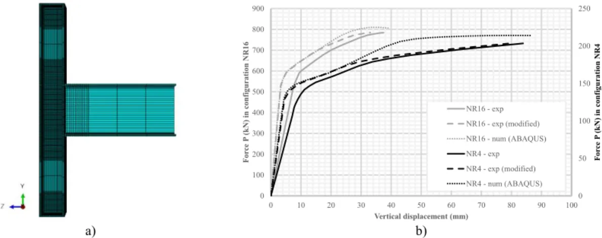
However, a major difference between the two studies concerns the type of element used: shell elements in (10) and brick elements in the present study. This is due to the fact that the root fillets in the column profile are believed to play a significant role in the behaviour of the CWP and therefore have to be modelled properly what is not possible with shell elements. That being said, eight-node linear bricks with reduced integration (C3D8R elements) have been used for almost all the elements except for the root fillets which have been modelled through the use of six-node triangular prisms with full integration (C3D6 elements). Fig. 4a) gives a general overview of the final mesh. Both mesh density and finite element type have been selected based on a preliminary sensitivity analysis. A monotonic displacement history has been imposed to the beam tip in order to mimic the real loading conditions. Furthermore the beam end section has been properly restrained from out-of-plane displacement. Numerical simulations have been performed using a general static analysis.
a) b)
Fig. 4. Finite element modelling: a) Meshed model; b) Validation of the numerical model
Validation of the model has been performed through comparisons between experimental and numerical results in terms of force vs. vertical displacement at the beam tip, as shown in Fig. 4b). Following conclusions may be drawn from those comparisons:
Initial stiffness in the numerical model is significantly larger than the experimental one, what can be explained by the initial flexibility of the test set-up;
This discrepancy has been cancelled out by shifting the experimental curve to the left towards numerical results (see “modified experimental curves” in solid line in Fig. 4b)).
A satisfying matching may then be observed between modified experimental results and numerical ones, especially in terms of elastic stiffness and plastic resistance.
The second part of the curve is over-estimated by Abaqus©. This is due to the fact that strain-hardening properties as well as ultimate strength were not made available in (5) and therefore had to be assumed in (10). However this is not of much concern as it is only the first part of the curve which is being investigated in this study.
0 50 100 150 200 250 0 100 200 300 400 500 600 700 800 900 0 10 20 30 40 50 60 70 80 90 100 F or ce P (kN) in c on figu ration NR 4 F or ce P (kN) in c on figu ration NR 16 Vertical displacement (mm) NR16 - exp NR16 - exp (modified) NR16 - num (ABAQUS) NR4 - exp NR4 - exp (modified) NR4 - num (ABAQUS)
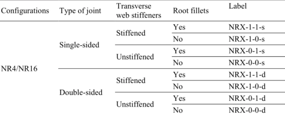
Configurations Type of joint Transverse web stiffeners Root fillets Label NR4/NR16 Single-sided Stiffened Yes NRX-1-1-s No NRX-1-0-s Unstiffened Yes NRX-0-1-s No NRX-0-0-s Double-sided Stiffened Yes NRX-1-1-d No NRX-1-0-d Unstiffened Yes NRX-0-1-d No NRX-0-0-d
The following assumptions have been made with the aim of isolating the behaviour of the PZ: the parametric study has been performed on welded connections only so as to reduce the
interactions with other components;
beam web has been disconnected from column flange in order to fix once and for all the value of the lever arm h in Eq. (1);
an elastic perfectly-plastic law (i.e. strain-hardening has been neglected) has been assumed for the column steel material to facilitate the derivation of the plastic resistance of the PZ;
Steel in the beam profile has been assumed to follow an indefinitely elastic law so as to prevent the occurrence of any failure mode in the beam prior to the yielding of the PZ.
a) b)
Fig. 5. Vwp-γ curves: a) Configuration NR4; b) Configuration NR16
Results of the parametric study are depicted in Fig. 5 in terms of shear force vs. shear distortion γ in the CWP. The influence of the different parameters is discussed here below:
Neither the type of joint (i.e. single-sided vs. double-sided) nor the presence of transverse web stiffeners affects the initial stiffness, this observation being in line with the conclusions derived in paragraph 2.
Yielding initiation ΔVy,k
Yielding initiation
Yielding initiates in the centre of the CWP and is not affected by surrounding elements. This is due to the fact that the stiffness of the CWP in shear is significantly higher than that of the surrounding elements; and so the CWP first “attracts” most of the forces.
Yielding very quickly spreads across the entire panel, as depicted in Fig. 5a). The plastic resistance of the CWP is reached, for a Vy,Rk value. Extra shear forces are then transferred to the surrounding elements which most of the time contribute with a ΔVy,Rk value to the resistance of PZ, before large plastic rotations develop.
For unstiffened single-sided configurations, initiation of yielding occurs earlier because of strong stresses interaction at the level of the beam flanges, where loads are introduced in the PZ. Furthermore, the contribution of the surrounding elements remains very low with respect to the resistance of the CWP (see Fig. 5b)).
5 CONCLUSIONS AND PERSPECTIVES
Results clearly show that the behaviour of the PZ may always be divided into the contributions of the CWP (Vy,Rk) and of the surrounding elements (ΔVy,Rk), as follows:
Vwp,Rk= Vy,Rk+ ΔVy,Rk (5)
For the contribution of the CWP, a similar formalism may be adopted as the one proposed in EC3 (see Eq. (6)), with the major difference that the shear area needs to be re-evaluated, this conclusion being in line with the main conclusion drawn in (10). In addition, further investigations will also focus on the stress interaction factor ρ in Eq. (6) whose use seems relevant for single-sided joints but is much more questionable in the case of double-sided joints.
Regarding the contribution of the surrounding elements, it is proposed to always account for this beneficial effect and not only in the presence of transverse stiffeners as it is currently stated in EC3. Therefore, future works will also be dealing with the definition of this second contribution.
Vy,Rk=ρ ∙ AVC∙ fy,wc
√3 (6)
REFERENCES
1. Jaspart, J.P. and Weynand, K. Design of Joints in Steel and Composite Structures. Berlin : Ernst & Sohn, 2016. p. 388.
2. Jaspart, Jean-Pierre. Recent advances in the field of steel joints, column bases and further
configurations for beam-to-column joints and beam splices. MSM, Liège University. 1997. p. 59.
3. CEN. Part 1-8: Design of joints. Eurocode 3: Design of steel structures. May 2005.
4. CEN. Part 1-1: General rules and rules for buildings. Eurocode 3: Design of steel structures. May 2005.
5. Klein, H. Das elastisch-plastiche Last-Verformungsverhalten M-theta steifenloser, geschweisster
Knoten für die Berechnung von Stahlrahmen mit HEB-Stützen. Fakultät für Bauingenieurwesen und
Architektur, Innsbruck University. 1985. p. 202.
6. Janss, J., Jaspart, J.P. and Maquoi, R. Strength and behaviour of in-plane weak axis joints and
of 3-D joints. JCachan : s.n., 1988. State-of-the art workshop on connections and the behaviour,
strength and design of steel structures. pp. 60-68.
7. Mele, E., Calado, L. and De Luca, A. Experimental Investigation on European Welded
Connections. 10, 2003, Journal of Structural Engineering, Vol. 129, pp. 1301-1311.
8. Project EQUALJOINTS-PLUS under the Grant Agreement n°754048. (RFCS), Research Fund
for Coal and Steel.
9. Brandonisio, G., De Luca, A. and Mele, E. Shear strength of panel zone in beam-to-column
connections, 2012, Journal of Constructional Steel Research, Vol. 71, pp. 129-142.
10. Atamaz Sibai, W. and Frey, F. Numerical simulation of the behaviour up to collapse of two