Faculty of Applied Sciences
Crashworthiness of offshore wind turbine jackets
based on the continuous element method
Dissertation submitted for the degree of
Doctor in Applied Sciences
by
Timoth´ee Pire
FRIA Research-Fellow
Nowadays, the offshore wind industry is expanding fast and many wind farms will be built in the near future. For every new project, a complete collision risk analysis is required. Usually, the crashworthiness of an offshore structure is assessed with non linear finite element simulations that provide accurate results but are time-demanding. Such approach is relevant in the final design but is not suitable at pre-design stage for which hundreds or sometimes thousands of collision scenarios have to be investigated. The purpose of this PhD thesis is thus to develop simplified semi-analytical formulations to compute quickly the resistance of an offshore wind turbine jacket impacted by a ship.
Based on finite element simulations, the structural behaviour of a collided jacket is described and four deformation modes are identified, namely the local crushing of the impacted tubular members, the global deformation of the whole jacket, the punching of legs by compressed braces and the deformation at the base of the jacket legs.
For each of them, closed-form expressions describing the evolution of the resistant force with the ship penetration are developed and validated using the finite element software LS-DYNA. The resistance related to the deformation modes involving a cross-section modification is derived using an analytical approach based on the upper-bound theorem associated with a plastic limit analysis. Considering the global deformation of the overall jacket, a methodology similar to nonlinear finite elements is developed, in which each tubular member is modelled as one single 3D beam element.
The total resistant force of the collided jacket is computed with an algorithm based on the continuous elements method. The collision time is split into short time steps for which the resistant force is computed for the four deformation modes; the total resistant force at the considered time step is assumed to be the minimum one. As the deformation in one mode may have an effect on the other ones, their interactions are accounted for in the formulations previously described.
Resistant forces and dissipated energies calculated from this semi-analytical method are then compared to finite element simulations for a wide range of collision scenarios involving initial kinetic energies up to 75 M J . Finite element and semi-analytical results are in good agreement, which validates the presented innovative developments and algorithm.
Actuellement, l’industrie de l’´eolien offshore grandit rapidement et plusieurs parcs d’´eoliennes vont ˆetre construits dans un avenir proche. Pour chaque nouveau projet, une analyse de risque exhaustive est demand´ee. Habituellement, la r´esistance `a l’impact d’une structure offshore est ´evalu´ee grˆace `a des simulations par ´el´ements finis qui fournissent des r´esultats pr´ecis mais demandent un temps de calcul important. Une telle approche est pertinente dans la phase finale de dimensionnement mais n’est pas adapt´ee `a une ´etape de pre-design pour laquelle des centaines voire des milliers des scenarios de collisions doivent ˆetre investigu´es. L’objectif de cette th`ese de doctorat est donc de d´evelopper des formulations simplifi´ees semi-analytiques pour calculer rapidement la r´esistance d’une ´eolienne offshore impact´ee par un navire.
Sur base de simulations par ´el´ements finis, la r´eponse structurelle d’un jacket impact´e est d´ecrite et quatre modes de d´eformation sont identifi´es, `a savoir l’´ecrasement local des cylindres impact´es, la d´eformation globale de l’ensemble du jacket, le poin¸connement des legs par les braces comprim´es et la d´eformation `a la base des legs du jacket.
Pour chacun d’eux, des expressions univoques d´ecrivant l’´evolution de la force r´esistante par rapport `a l’avancement du bateau sont d´evelopp´ees et valid´ees avec le logiciel de calcul par ´el´ements finis LS-DYNA. La r´esistance li´ee aux modes de d´eformation qui impliquent une modification de la section transversale est obtenue en utilisant une approche analytique bas´ee sur le th´eor`eme de la borne sup´erieure associ´e `a une analyse limite plastique. Concernant la d´eformation globale du jacket, une m´ethode similaire `a celle des codes ´el´ements finis non lin´eaires est d´evelopp´ee et chaque cylindre est mod´elis´e en tant qu’un unique ´el´ement de poutre 3D.
La force r´esistante totale du jacket impact´e est calcul´ee `a l’aide d’un algorithme bas´e sur la m´ethode des ´el´ements continus. La dur´ee de la collision est subdivis´ee en plusieurs courts pas de temps pour lesquels la force r´esistante est calcul´ee pour chacun des quatre modes de d´eformation; la force r´esistante totale pour le pas de temps consid´er´e est suppos´ee ˆetre la force minimum. Puisque la d´eformation dans un mode peut avoir un effet sur les autres, leurs interactions sont prises en consid´eration dans les formulations d´ecrites pr´ec´edemment et sont mises `a jour `a chaque pas de temps.
Les forces r´esistantes et ´energies dissip´ees calcul´ees avec cette m´ethode semi-analytique sont ensuite confront´ees aux simulations par ´el´ements finis pour une large gamme de sc´enarios de collision et avec des ´energies cin´etiques initiales allant jusque 75 M J . Les r´esultats obtenus `a l’aide du code semi-analytiques corr`elent bien avec ceux issus des calculs par ´el´ement finis, ce qui valide les d´eveloppements innovants et l’algorithme pr´esent´es.
Alors qu’un doctorat peut de prime abord sembler ˆetre un travail individuel, de nombreuses personnes m’ont accompagn´e et soutenu dans ce projet et m’ont aid´e `a aboutir `a ce r´esultat.
Je tiens tout d’abord `a remercier mon promoteur, le Prof. Philippe Rigo, pour m’avoir propos´e ce doctorat et pour m’avoir conseill´e tout au long de celui-ci. De plus, grˆace `a ses nombreux contacts dans le domaine des structures hydrauliques, il m’a introduit aupr`es de scientifiques et industriels sp´ecialis´es dans mon domaine de recherche. Cela m’a ainsi permis d’apporter un point de vue neuf sur mon travail.
Mes remerciements vont ´egalement au Prof. Herv´e Le Sourne de l’ICAM Nantes qui supervise le projet de recherche consacr´e aux impacts de navires au sein de son institution et de l’Universit´e de Li`ege. Son expertise dans le domaine des m´ethodes num´eriques et analytiques qu’il a partag´ee sans r´eserve avec moi au cours de ses s´ejours r´eguliers `a Li`ege ainsi que lors de mes visites `a Nantes m’a ´et´e indispensable. Je le remercie ´egalement pour son implication et sa grande disponibilit´e.
Merci aux membres de mon comit´e de th`ese, les Profs. Vincent Deno¨el et Laurent Duchˆene, ainsi qu’aux membres du jury pour les conseils avis´es qu’ils ont pu m’apporter.
Je remercie ´egalement tous mes coll`egues pour leur bonne humeur et tous les bons moments pass´es ensemble. Un merci plus sp´ecifique pour ceux avec qui j’ai partag´e le bureau, Lo¨ıc, Andreea et Sara, avec qui l’ambiance a souvent ´et´e studieuse mais heureusement r´eguli`erement ponctu´ee de rires.
Ma famille m’a beaucoup soutenu et encourag´e. Merci `a mes parents, mes fr`eres et soeurs, mes amis ; grˆace `a leurs questions et leur int´erˆet, j’ai appris `a faire comprendre mon travail, `a le rendre accessible `a tous et ainsi `a mieux l’exprimer.
Mon ´epouse, Tatiana, est ´egalement pass´ee par le doctorat et sait ce que cela repr´esente. Merci pour ses conseils, pour m’avoir pouss´e jusqu’au bout en toutes circonstances, mais aussi et sourtout pour son soutien et ses petites attentions quotidiennes.
Merci finalement `a toutes les personnes qui, par leur bienveillance, m’ont donn´e la motivation et l’entrain jusqu’au terme de ce travail.
Je souhaite remercier le Fonds pour la Formation `a la Recherche dans l’Industrie et l’Agriculture (FRIA-FNRS) pour la confiance donn´ee dans mon projet de doctorat et dans mes capacit´es `
a mener `a bien ce travail ainsi que pour son soutien financier durant ces quatre ann´ees de recherches. Dans le cadre de cette bourse, le Bureau Greisch et Electrabel ont soutenu ce projet et m’ont aid´e `a cerner les besoins des entreprises.
Merci ´egalement `a STX France et au Bureau Veritas pour leur participation dans la d´efinition des objectifs du projet. Merci finalement `a MSC (PATRAN-NASTRAN ) et `a LSTC (LS-DYNA) pour l’aide technique fournie durant ce doctorat.
CoV Coefficient of Variation
DNV Det Norske Veritas
EU European Union
EWEA European Wind Energy Association
FE Finite Elements
FEA Finite Element Analysis
GWEC Global Wind Energy Council
ICAM Institut Catholique d’Arts et M´etiers
IPCC Intergovernmental Panel on Climate Change (GIEC in French)
ISUM Idealised Structural Unit Method
OSV Offshore Supply Vessel
OWT Offshore Wind Turbine
SI International System of units
ULi`ege University of Li`ege
Units
Abstract . . . i R´esum´e . . . ii Remerciements . . . iii Acronyms . . . iv Units . . . iv Contents . . . vii
1 Introduction and state of the art 1 1.1 Context of the research . . . 2
1.2 Ship collisions state of the art . . . 10
1.2.1 Experimental methods . . . 10
1.2.2 Empirical methods . . . 12
1.2.3 Numerical methods . . . 12
1.2.4 Simplified analytical methods . . . 15
1.3 Aim of the research . . . 17
1.4 Structure of the thesis . . . 19
Bibliography . . . 20
2 Collision risk analysis for offshore structures 27 2.1 Introduction . . . 28
2.2 Assessment of collision events probability . . . 28
2.3 Existing methods to assess the crashworthiness . . . 29
2.3.1 Finite element method . . . 30
2.3.2 Plastic limit analysis approach . . . 30
Bibliography . . . 34
3 Ship collision on offshore wind turbine jacket analysis 35 3.1 Introduction . . . 36
3.2 Collision description . . . 37
3.2.1 Striking ship description . . . 37
3.2.2 Collided offshore wind turbine jacket description . . . 40
3.2.3 Collision scenario description . . . 43
3.3 Key parameters governing the jacket crashworthiness . . . 46
3.3.1 Gravity loads effect . . . 46
3.3.2 Turbine and tower effect . . . 47
3.3.3 Soil stiffness effect . . . 47
3.4 Finite element analysis of an offshore wind turbine jacket impacted by a ship . . 48
3.4.1 Collisions assumptions . . . 48
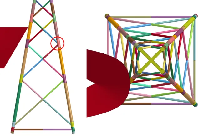
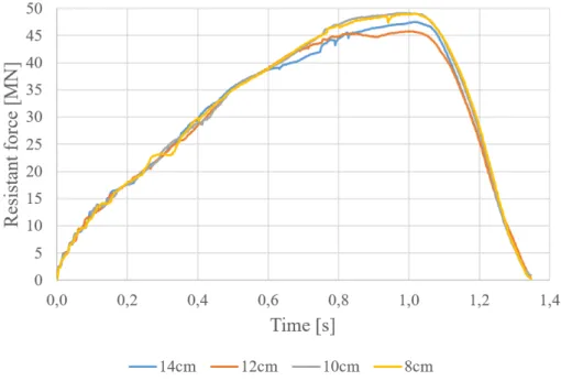
3.4.2 Mesh size sensitivity analysis . . . 49
3.5 Deformation modes of the impacted offshore wind turbine jacket . . . 52
3.5.2 Discussion on the braces properties . . . 55
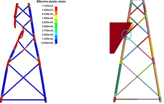
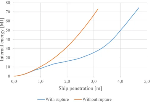
3.6 Effect of rupture criteria . . . 56
3.7 Conclusions . . . 58
Bibliography . . . 60
4 Local crushing of impacted tubular members 61 4.1 Introduction . . . 62
4.2 Description of the collision scenario . . . 63
4.3 Impact on a vertical tubular member . . . 65
4.3.1 Deformation mechanism . . . 65
4.3.2 Definition of the displacement field . . . 69
4.3.3 Local crushing resistance . . . 70
4.3.4 Global crushing resistance . . . 73
4.4 Impact on a horizontal tubular member . . . 76
4.4.1 Deformation mechanism . . . 76
4.4.2 Definition of the displacement field . . . 79
4.4.3 Local crushing resistance . . . 79
4.4.4 Global crushing resistance . . . 80
4.5 Impact on an oblique tubular member . . . 82
4.5.1 Crushing resistance . . . 82
4.5.2 Numerical validation . . . 83
4.6 Impact on a full-scale jacket . . . 89
4.7 Extension to bulb-tubular member collision . . . 91
4.7.1 Collision description . . . 91
4.7.2 Numerical validation . . . 94
4.8 Conclusions . . . 97
Bibliography . . . 98
5 Global deformation of the whole jacket 99 5.1 Introduction . . . 100
5.2 Description . . . 101
5.2.1 Elementary elastic stiffness matrices . . . 101
5.2.2 Stiffness reduction due to plastic hinges . . . 106
5.2.3 Assembly . . . 114
5.2.4 Displacement control . . . 116
5.2.5 Matrices system resolution . . . 117
5.2.6 Internal forces . . . 117
5.3 Implementation . . . 117
5.4 Buckling of compressed tubular members . . . 118
5.5 Numerical validation . . . 121
5.6 Conclusions . . . 128
Bibliography . . . 129
6 Punching of legs by compressed braces 131 6.1 Introduction . . . 132
6.2 General description of the punching deformation process . . . 133
6.3 Semi-analytical developments to assess the punching behaviour on one connection 136 6.3.1 Deformation mechanism . . . 136
6.3.2 Semi-analytical developments . . . 144
6.3.3 Validation for punching on one connection . . . 152
6.4.1 Methodology to assess punching on the whole jacket . . . 169
6.4.2 Validation on a full-scale jacket . . . 175
6.5 Conclusions . . . 177
Bibliography . . . 180
7 Deformation at the base of the jacket 181 7.1 Introduction . . . 182
7.2 Description of the deformation mechanism . . . 183
7.3 Derivation of deformation energy rates for zones A to D . . . 186
7.3.1 Zone A: rear leg at horizontal brace level . . . 187
7.3.2 Zone B : impacted leg at horizontal brace level . . . 194
7.3.3 Zone C : rear leg near foundation level . . . 195
7.3.4 Zone D : impacted leg between foundation and horizontal brace level . . . 200
7.4 Numerical validation . . . 202
7.5 Conclusion . . . 208
Bibliography . . . 209
8 General algorithm to assess the crashworthiness of an offshore wind turbine jacket 211 8.1 Introduction . . . 212
8.2 Ship - jacket collision models . . . 213
8.3 Collision points . . . 213
8.3.1 Detection of potential impacted tubular members . . . 213
8.3.2 Distance from the striking ship to the jacket members . . . 215
8.4 Computation of the total resistant force . . . 219
8.4.1 Deformation mode involved for each time step . . . 219
8.4.2 Implementation and interactions of the four deformation modes . . . 224
8.5 Numerical validation for ship-jacket collisions . . . 227
8.5.1 Comparison of numerical and semi-analytical results . . . 227
8.5.2 Discussion of the results . . . 248
8.6 Conclusions . . . 252
Bibliography . . . 253
9 Conclusions and perspectives 255 9.1 Summary of the research . . . 256
9.2 Personal contributions . . . 260
9.3 Perspectives . . . 262
A Finite element method theory in the framework of ship collisions 265 A.1 Introduction . . . 265
A.2 Theoretical aspects . . . 268
A.3 Treatment of contacts in LS-DYNA . . . 272
Introduction and state of the art
Abstract:
The purpose of this introduction is to describe the context of the offshore wind industry and the existing scientific work performed in relation to ship collisions in order to demonstrate the interest of this PhD.
It is agreed that earth global warming is related to pollution due to human activities, and a reduction of fossil fuel resources consumption appears to be mandatory to prevent major environmental damage. Re-newable sources of energies need therefore to be more extensively devel-oped. Amongst them the offshore wind industry is expanding quickly and the number of offshore wind turbines (OWT) installed worldwide is increasing yearly. Similarly, the number of ships rises also. Due to those two factors, the probability of a collision between a ship and an offshore wind turbine increases as well. As required by design standards, this loading case has to be investigated during the design process.
Several authors studied the resistance of offshore or naval structures im-pacted by a ship using experimental, empirical, numerical or analytical methods. Their main results are discussed and provide a useful state of the art for the present thesis. Regarding the crashworthiness of OWT jackets, numerical simulations were already performed to study the be-haviour of such impacted structures. However, the large computation time required by the FE method makes it not suitable for a pre-design stage and complete collision risk assessment. The development of a sim-plified method, which is the aim of my PhD thesis, becomes therefore a major interest for a preliminary design phase.
1.1
Context of the research
For several years, the energetic context is being submitted to a complete mutation. In the past, fossil resources (fuel, coal, uranium, . . . ) were used as the only source of energy available for industry, transportation, personal use, . . . Today, it appears that the use of those resources has to be limited.
First, the combustion of most fossil fuels produces several polluting gases, amongst them the well-known CO2. Today, several scientific researches demonstrated that the global warming at
earth scale is related to the increase of gases emission, which significantly started to increase at the beginning of the 20th century, with the development of industry and the emergence of additional countries in the worldwide economy. Princiotta [63] gives the record of carbon dioxide concentration and the global warming since 1750 and proposes a model to predict the values until 2100 (Figs. 1.1 and 1.2 respectively).
Figure 1.1: CO2 concentration measurements and projections [63]
According to the 5th IPCC (GIEC in French) report published in 2013 [37], the global warming should be limited to 2◦C with regard to the pre-industrial period to prevent irre-versible climate changes and natural disasters such as cyclones, drought, loss of species, sea level elevation, . . . This objective of 2◦C temperature elevation was signed by 195 countries in 2015 during the COP21 taking place in Paris.
Uranium that is used in the nuclear power plants is also a fossil resource. Even if those plants do not emit any polluting gases, the treatment and storage of the nuclear wastes remains a challenging issue. The potential danger of such installation has also to be considered, as the accidents of Tchernobyl or Fukushima reminded.
In addition to the pollution issue, the fossil resources are depleting. Even if it is difficult to predict when the resources will be missing, it appears anyway that the cost required to get access to fossil fuels will increase with the complexity to extract them.
Figure 1.2: Temperature variation with regard to 1990 measurements and projections [63]
To overcome those issues, researches are performed to develop innovative sources of energy. In order to reduce as much as possible the amount of polluting substances emitted, renewable sources of energy are mainly investigated, such as wind (wind turbines), sun (solar or photo-voltaic panels), water (hydroelectric power plants, technologies based on waves1 or tidal, . . . ), biomass and geothermal energy. Any of those sources may be considered as better than another one. Their use depends on the local conditions where sources of energy are required, and it appears that all the technologies are complementary.
The present thesis focuses on wind energy, and specifically to offshore wind turbine jackets. Wind energy was used for centuries for navigation purpose and for wind mills. The first record of a wind turbine developed to produce electricity is from 1887. It was created by Charles Brush and built in Cleveland, USA (Fig. 1.3) [23].
Later on, the technology was improved and the turbines power increased rapidly. The first generator with more than 1 M W was built in 1941.
The first offshore wind farm, named Vindeby, was built in Denmark in 1991. It consists in 11 turbines with a power of 450 kW each [65].
Until then, the wind power installed is increasing constantly. According to the Global Wind Energy Council (GWEC) [33], the wind power (onshore and offshore) installed yearly worldwide is increasing constantly since 2000 (except in 2013) until 2015, as can be seen in Fig. 1.4. The corresponding cumulative wind capacity is expanding fast, as represented in Fig. 1.5. Republic of China represents the largest wind power installed in the world in 2015, with 33.6% of the total worldwide capacity, followed by the USA (17.2%) and Germany (10.4%), as given in Fig. 1.6. As long as all the countries of EU are considered, they represent 32.7% with 141.6 GW installed [33].
Figure 1.3: Turbine developed by Charles Brush in 1887 [23]
Figure 1.4: World annual wind capacity installed [M W ] [33]
Figure 1.6: Worldwide repartition of cumulative wind capacity installed [33]
The European Wind Energy Association (EWEA) [32] collects wind data for the continent. Similarly to the worldwide trends, a large expansion of the cumulative wind capacity (onshore and offshore) may be noticed, as represented in Fig. 1.7. The total power installed was equal to 141.6 GW in 2015, which corresponds to 15.6% of the electricity production in EU (Fig. 1.8), less than gas and coal, but more than water and nuclear power [32]. The wind cumulative power for the most representative countries in EU is given in Table 1.1.
Figure 1.7: Europe cumulative wind capacity installed [GW ] [32]
In EU, it appears that most of the wind power installed is onshore, but the part of offshore wind is increasing regularly, as can be seen in Fig. 1.9 [32], and is expected to continue growing. With regard to onshore wind turbines, building offshore wind farms is more complex and more expensive. All the turbines have to be connected to a substation, and electricity is then driven to shore through a long cable, which causes a voltage drop and therefore a loss of power. Offshore maintenance is also a task more complex than onshore because it requires ships navigating within the wind farms, which makes it more expensive and increases the probability of collisions.
Figure 1.8: EU energy mix in 2015 [32]
Table 1.1: Cumulation wind power repartition in EU [32]
Pos. Country Cumulative wind power [GW ] EU percentage
1 Germany 44.9 31.7 2 Spain 23.0 16.2 3 UK 13.6 9.6 4 France 10.4 7.3 5 Italy 9.0 6.3 . . . 14 Belgium 2.2 1.6
However, offshore wind farms may take advantage of higher and more constant wind speeds that are not disturbed by hills or buildings. In addition, they are built far from shore and have less incidence on human being (noise, landscape modification, . . . ). This allows also for larger wind turbines and therefore for larger unitary power.
Offshore wind remains therefore an attractive electricity power production system. The evolution of the offshore wind installed power in Europe is given in Fig. 1.10 [31].
Figure 1.10: Yearly installed and cumulative offshore wind power installed in 2015 [31] Most of the offshore power installed is in UK (45.9% of EU installed power in 2015), followed by Germany (29.9%), Denmark (11.5%) and Belgium (6.5%) [31]. The detail of total number of farms, wind turbines and offshore power installed in 2015 is given in Fig. 1.11.
Figure 1.11: EU wind farms, wind turbines and offshore wind power installed in 2015 [31] Several types of offshore wind turbine substructures exist, mainly chosen according to the water depth at the wind turbine location, as represented in Fig. 1.12 [6]. Up to 30 m, monopiles are mainly used. Until 60 m, jackets are the most common structures while floating wind turbines are preferred for deeper waters.
In 2016, monopiles represented more than 80% of the offshore wind turbines substructures installed, while the part of jackets was 6.6%. Only 1 floating turbine was installed, corresponding to less than 0.1% of substructures, and the rest consists in tripods, tripiles and gravity base foundations.
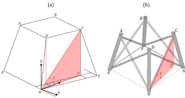
In this thesis, we focus only on OWT jackets, which is a supporting structure composed of 4 legs (main tubular members) connected by many inclined braces (smaller tubular members). The general shape of that structure is a truncated pyramid with 4 faces (Fig. 1.13).
Figure 1.12: Offshore wind turbine foundation types [6]
The size and unitary power of the offshore wind turbines expands fast. Today, the length of a blade could reach more than 80 m, longer than the Airbus A380 wingspan. The average turbine rated capacity in 2016 was 4.8 M W , while it was 4 M W in 2012, 3 M W in 2005 and 2 M W in 2000. Prototypes of turbines now even reach a power of 8 M W .
As can be seen from these data, the number of installed wind farms is growing, and it is still expected to develop in the next years.
In parallel, the number of navigating ships is also increasing worldwide. The vessels become in addition larger and heavier.
Combining the increase of offshore wind turbines and navigating ships rises the probability of a collision between them, even with the improvement of navigation systems (radar, GPS, . . . ). In the literature, only few accidents are reported. However, Kvitrud [43] listed the collisions involving ships and platforms in Norway. Since 1982, 115 collisions were reported, amongst them 26 in the period 2001-2010. No death or injuries were caused during those incidents, but the material damage was important in some cases. The main collision properties described in [43] are summarised in Table 1.2.
Table 1.2: Significant ship - platform collisions in Norway properties
Date Mass [tons] Velocity [m/s] Energy [M J ]
March 7th, 2004 ≈ 5, 000 3.7 ≈ 39
June 2nd, 2005 ≈ 4, 700 ≈ 3 > 20
November 13th, 2006 ≈ 100, 000 1.2 ≈ 60
July 18th, 2007 ≈ 3, 100 1 − 3.5 1.5 − 20
June 8th, 2009 ≈ 6, 000 ≈ 4.8 ≈ 70
Robson [66] collected all the incidents between ships and platforms in the UK Continental Shelf between January 1st, 1975 and October 31st, 2001. From the database, 557 collisions were recorded on that period, and amongst them 17 were considered as severe (without more details on the notion of severity).
In the Offshore Design Standards edited by Det Norske Veritas (DNV) [21] and the American Petroleum Institute (API) [5], it is required to perform a complete collision risk analysis for every new offshore project. This consists in assessing the structural behaviour of both the striking ship and the offshore structure for a large range of parameters related to the ship (type, geometry, internal reinforcement, material, . . . ), to the structure (geometry, material, . . . ) and the collision itself (impact point, ship trajectory, ship mass and initial velocity, . . . ). The notion of risk involves also the probability of a collision to occur, as will be discussed in Section 2.2.
The minimum collision energy that has to be investigated, according to DNV [21] is 14 M J for sideways collisions and 11 M J for bow or stern collisions, which corresponds to a ship with a 5, 000 tons displacement and an initial velocity of 2 m/s. The American Petroleum Institute (API) [5] requires to consider a vessel of 1, 000 tons colliding the structure at a velocity of
0.5 m/s, which is much lower than the DNV requirements. Those initial kinetic energies are below the collision energies reported by Kvitrud [43] (up to 70 M J ).
In practice, each collision scenario has to be investigated before validating the offshore struc-ture design. Due to the large number of parameters, this represents hundreds or even thousands of scenario to analyse. Several design methods exist and are discussed in the next Section 1.2 and in Chapter 2.
1.2
Ship collisions state of the art
Ship collisions were investigated by many authors.
Zhang [96] listed four types of methods in the case of ship-ship collisions that are also valid for ship - offshore structures impacts, namely:
• Experimental methods; • Empirical methods; • Numerical methods;
• Simplified analytical methods.
1.2.1 Experimental methods
Experimental methods remain the most reliable ones, as they include all the physical phenomena involved in a real collision event.
Most of the experiments were conducted on small parts of the structure. One may note, as an example, the ship hull resistance to an impact in order to prevent oil spills that was investigated in many studies, amongst them in Amdahl [2], Pedersen et al. [58] or Qvist et al. [64]. More recently, other experiments were conducted to analyse the crushing resistance of some structural parts of a collided ship, such as the one performed by Liu et al. [47] for web girders, Karlsson et al. [41] or Zhang et al. [95] for plates with lateral deformation, Simonsen and Ocakli [68] for folded plates, amongst others.
Experiments were also conducted on tubular members, which compose an OWT jacket. For example, Cerik et al. [18] performed low-velocity mass impact on a tubular structures and discussed the effect of the geometrical parameters (diameter, thickness, length) on the local denting and global displacement of the structure. The deformed structure after the collision for one set of parameters is illustrated in Fig. 1.14. The results obtained with the experimental tests were used to validate numerical (USFOS and ABAQUS ) and analytical tools, that were shown to be in good accordance for most cases.
Figure 1.14: Deformation tubular structure after a low-velocity impact, as performed by Cerik et al. [18]
Other experimental studies were conducted by Watson et al. [83, 84], Ellinas and Walker [30], Jones et al. [40], Zeinoddini et al. [94] or Cho et al. [19], amongst others. For all those exper-iments, drop tests were performed on tubular members in order to analyse the influence of geometrical parameters. The results presented by those authors allow to identify the main pa-rameters governing the tubular members behaviour, which are the tubular member diameter and thickness, the location of the impact and the energy dissipated during the impact.
Only few full-scale experimental tests of ship collisions were performed, due to the high complexity to built and install the experiment and to its cost. However, some results of full-scale ship collision are published by Wevers et al. [85], Tabri et al [75] (Fig. 1.15) or Ehlers [24]. The striking ship was equipped with a very rigid bulb and collided structures fixed on another vessel. Sensors were used to record forces and accelerations of both ships.
Figure 1.15: Full-scale ship collisions [75]
Scaled experiments were performed by Tabri et al. [76] by applying Froude scaling law on polyurethane foam ship models to analyse the external dynamics of the collision. However, the damage on both scaled ships could not be properly represented with those models.
Other scaled collisions were performed to optimise the stiffening systems of collided ships and analyse the influence of the striking ship shape. One may note for example the experiments conducted in Germany by Woisin [88] (Fig. 1.16) and in Japan whose results were presented by Akita et al. [1]. More recently, Calle et al. [17] also performed various experimental simulations
of scaled model including collisions against a rigid wall, grounding or ship-ship collisions. For all of them, validations were performed by comparison with finite element simulations.
Figure 1.16: Scaled experiments of ship collisions performed by Woisin [88]
Regarding ship collisions on offshore wind turbine substructures, no article involving full-scale or full-scaled models were found in the literature.
1.2.2 Empirical methods
Empirical laws consists in expressions based on several experimental results used to describe physical phenomena. One of them was developed by Minorsky [50] to describe the dissipated energy and the volume destroyed for both the striking and struck ship after a collision. Other empirical formula were then established based on recorded accidents, such as Hagiwara et al. [34] or Suzuki et al. [74], but their application requires to investigate a ship with similar geometrical and mechanical properties than the ones considered to establish the formula.
Due to the lack of data available in the literature for ship - offshore structure, empirical laws do not exist to our knowledge in the investigated field.
1.2.3 Numerical methods
Nowadays, design offices mainly use finite element (FE) simulations to assess the resistance of an offshore structure impacted by a ship. Many researchers also used this method to investigate the structural behaviour of collided wind turbine jackets. Numerical assumptions that have to be performed were investigated by Biehl [11], Paik [53] or Pire et al. [60] amongst others.
As detailed in Section 1.1, design standards impose to consider initial kinetic energy of 14 M J . Additional analyses were however performed to analyse the dynamic behaviour of a jacket impacted by ships with higher initial kinetic energies, such as performed by Amdahl and Johansen [4], Travanca and Hao [78, 80] or Moulas et al. [51] (Fig. 1.17). Those papers highlight the large deformation and plasticity that the jacket may suffer with energy impact of about 50
to 60 M J . Vredeveldt and Schipperen [81] investigated the jacket geometrical and mechanical properties to improve the collision resistance and identified the best geometrical arrangements to resist ship impacts.
Figure 1.17: Ship - OWT jacket FE simulation, as performed by Moulas et al. [51] Le Sourne et al. [44] investigated the effect of additional parameters, still using nonlinear FE simulations. It is shown that gravity loads have little influence on the behaviour of the jacket subjected to an impact and can therefore be neglected. They also conducted analyses with the soil stiffness as a parameter, considering it alternatively as rigid or as flexible. Comparisons between both behaviours show negligible differences. This will be discussed in more details in Section 3.3.
The stiffness of the striking ship is also important as the energy dissipation is related to the relative stiffness between both striking and struck structures. As shown in [44], several types of ships have completely different stiffnesses, an OSV bow being more flexible than an ice class bulk carrier side shell, for instance. Even if the striking ships will be considered as rigid in this thesis, the relative stiffness between the ship and the jacket will have to be investigated for further research.
Finite element simulations were also performed to assess the resistance of tubular members only submitted to lateral impacts. Soreide et al. [69, 71] computed the energy dissipation capacity of tubular members impacted laterally and discussed the residual resistant capacity of the dented cross-section. The reduction of carrying capacity of the dented section was also investigated by de Oliveira et al. [20]. Recent studies were conducted to analyse the effect of the indenter shape or the impact location along the tubular member, such as Travanca and Hao [79] (Fig. 1.18) or Cerik et al. [18].
Figure 1.18: Deformation of the impacted tubular member for two indenter shape [79]
The effect of axial pre-loading on the tubular member resistance to lateral impact was also numerically investigated by Zeinoddini et al. [92, 93] or Khedmati et al. [42] and the models were validated with experimental results.
Even if FE algorithms are a useful tool to assess the resistance of a collided structure, two limitations remain, as mentioned here and detailed in Section A.
First of all, this method is time consuming because a fine mesh is required to get accurate results in the framework of collisions. In order to reduce the computation time, one may use FE formulations and consider each jacket tubular member as one single finite beam element. This idea was followed to create the software USFOS [70]. The software includes potential yielding at each tubular extremities and at midspan, large deformation formulations and joint resistance checks. However, the cross-section deformations are not included. Collisions simulations per-formed with USFOS were published by Tran [77] or Amdahl and Holmas [3], amongst others. This method is shown to provide accurate results with regard to FE simulations. Computation time may be also saved by combining numerical and semi-analytical method. As an example, Ehlers and Tabri [27] investigated the damage of a collided ship. Therefore, one single collision scenario is computed with FE simulation and the results are extended to other scenarios with semi-analytical expressions.
Then, modelling the rupture of a component is still arduous. Indeed, material rupture threshold are often defined using uniaxial traction tests. For collided structure, the stress state is most of time more complex than pure traction in the critical areas. Several material failure laws were developed for multiaxial stress states, but their application remain limited to some specific internal stresses distribution cases and most of them are not implemented in FE solvers yet. Failure laws are discussed with more details in Section A based on the work performed by Ehlers et al. [25, 26, 28], amongst others.
1.2.4 Simplified analytical methods
Another approach to compute quickly the resistance of an offshore jacket is to use simplified methods based on analytical formulations.
In the framework of collisions, this idea was first applied by Ito et al. [38], Yukio et al. [91] and Paik et al. [56] under the name of Idealized Structural Unit Method (ISUM). This method consists in dividing the structure into large sub-elements for which the plastic deformation is described by an analytical formulation, including folding, yielding, crushing or rupture. In addition, the interaction between all those sub-elements is ensured with a classical FE assembly method. It was demonstrated that this method provides accurate results within a computation time shorter than with FE simulations. Applications of this method were developed by Paik and Pedersen [54] to compute the damage of a collided ship, Paik and Thayamballi [57] for large steel plates transversally loaded or Pei et al. [59] for ships submitted to extreme wave loading, amongst others.
Other authors derived simplified analytical formulations for several impacted elements using the upper-bound theorem, as described by Jones [39]. One may note for example the work of Wierzbicki et al. [86], Wang et al. [82], Simonsen [67] or Zhang [96] (Fig. 1.19) for plates frontal crushing, Yu [90] for plates lateral loading or Amdahl [2] for plates crossings.
Figure 1.19: Initiation of plate folding [96]
As an extension to this work, L¨utzen [48] developed some analytical formulations to assess the deformation of a ship impacted by another ship. This involves formulations that describe the deformation of the bow, the decks and all the stiffening system of both striking and struck ships. The work of L¨utzen was then extended by Buldgen et al. [13] who adapted the so-called “super-element” method to ships oblique collisions and by Le Sourne et al. [45] who included the effects of hydrodynamic forces occurring during the ships rigid body movements. The scenarios of ship colliding lock gates was also studied by Buldgen et al. [15] for plane gates and by Buldgen et al. [16] for mitre gates. In the previous papers, the striking ship was considered to be rigid, which is conservative with regard to the collided structure.
Analytical formulations are similarly developed to assess the deformation of a ship colliding a rigid structure. The resistance and deformation of a ship bulb impacting an inclined rigid wall and rigid tubular member was studied by Buldgen et al. [12].
The deformation of tubular members, which compose the structure of an OWT jacket, was also investigated by several authors who developed analytical expressions able to describe their behaviour when submitted to localised lateral forces. The effect of local denting on the com-pressive load capacity of a tubular member is studied by Ellinas [29].
The model used for the local denting of such tubular members is later improved and described by Suh [73], Wierzbicki and Suh [87] or Hoo Fatt and Wierzbicki [35]. In those contributions, the authors introduce and describe a realistic deformation pattern of a tubular member submitted to a localised lateral load (Fig. 1.20). Using the principle of virtual velocities and plastic theorems, closed-form expressions are developed to assess the deformation of the cylindrical member for a given load. The effect of boundary conditions is also considered by applying rotation or axial displacement constraints at the tubular member extremities, and is demonstrated to have a large effect on the resistance to lateral loadings. The developed expressions are successfully validated by comparison with experimental results.
Figure 1.20: Dented cross-section, as modelled by Hoo Fatt and Wierzbicki [35]
While only local denting occurs for small indenter penetration, a global deformation is ac-tivated for larger ones, involving a plastic mechanism and a global deformation of the whole impacted tubular member. This phenomenon is described by analytical formulations developed by Paik et al. [55], taking into account several parameters such as the tubular member length, its diameter and thickness and the denting location.
1.3
Aim of the research
The state of the art detailed above confirms that the behaviour of impacted tubular members has been already investigated with experimental, numerical or analytical methods.
Ship impacts on complete OWT jackets are mainly investigated with numerical analyses that provide a good understanding of the collided jacket structural response and allow to identify the main governing parameters. As discussed, FE simulations provide accurate results but they are time-demanding.
Experimental tests are expensive and can hardly be performed to design a jacket against ship impacts. As only few ship collisions on OWT jackets have been recorded, empirical laws have not been developed.
Today, numerical methods seem therefore to be the main approach to assess the crashwor-thiness of an OWT jacket.
However, hundreds or thousands of collision scenarios have to be investigated to perform a complete collision risk analysis. In a pre-design stage, the geometrical and mechanical properties of the jacket are still to be defined, and all the collision scenarios have to be computed for several jacket designs. FE simulations are thus not convenient for this pre-design stage, as the computation time required would be too long.
It appears that a tool able to assess quickly the crashworthiness of an OWT jacket is missing. The purpose of this thesis is to answer this issue by developing a simplified method based an analytical approach to assess quickly the resistance of such collided structures. This method has to be suitable for a pre-design process and to identify the most critical collision scenarios for a given jacket design. Those scenarios could be then investigated in more details with FE models. The purpose of this tool is not to replace other design methods, such as FE analyses, but is a useful complement during the first design steps.
DNV standard [21] requires to investigate collisions of 14 M J (sideways impact) or 11 M J (bow or stern impact), which is much lower than the collisions reported by Kvitrud [43] going up to 70 M J . For the present thesis, it was decided to consider collisions up to 75 M J corresponding to a ship with a 6, 000 tons displacement and an initial velocity of 5 m/s. To be conservative with regard to the jacket, the striking ship will be considered as rigid, such as all the initial ship kinetic energy is dissipated by the collided OWT jacket alone.
The developed method is based on the upper-bound theorem associated with a plastic limit analysis. Assumptions on the deformation pattern of the impacted structure are required to use this theorem. FE simulations are thus performed to analyse the structural behaviour of the jacket and to identify the main deformation modes.
Closed-form expressions can then be derived to assess the resistance with regard to the ship penetration for all the identified deformation modes. The developed expressions are validated with FE simulations performed with LS-DYNA.
As the four identified deformation modes may occur simultaneously during a collision, an algorithm based on the so-called “continuous element method” has to be implemented to com-pute the total resistance of the jacket and take into account the interactions between all of them. The validation of the algorithm is achieved by comparing the results with FE simulations.
Several articles have been published by the author regarding the developed method, including the analytical developments used to describe the behaviour of some jacket component such as the impacted tubular members (Buldgen et al. [14]), the deformation due to punching (Pire et al. [62]) or the deformation at the base of the jacket (Pire et al. [61, 62]), the global algorithm (Pire et al. [60] and Le Sourne et al. [46]), or the numerical validation (Pire et al. [60]).
The same approach is followed by several researchers in the University of Li`ege (Belgium) and ICAM Engineering School in Nantes (France), under the supervision of Prof. Philippe Rigo and Prof. Herv´e Le Sourne. Ship collisions on OWT monopiles and on floating OWT are investigated by Ms. Andreea Bela [8, 9] and Ms. Sara Echeverry Jaramillo [22] respectively. Several Master Thesis related to ship collisions on offshore structures were also achieved in these two institutions, such as Mr. Andres Barrera Arenas [7], Mr. Jose Babu Maliakel [49], Ms. Jing-Ru Hsieh [36], Mr. Pierre Berthonneau [10], Mr. Anthony Soret [72] and Mr. Pyae Sone Oo Yeye [89].
1.4
Structure of the thesis
The present thesis is divided into 9 Chapters, each of them having its own bibliography. Chapter 1 Introduction and state of the art:
This Chapter presents the context of the research and describes the existing scientific work related to ship collisions. Based on the state of the art, the objectives of the thesis are defined and the structure of the thesis is described. Chapter 2 Collision risk analysis for offshore structures:
This Chapter provides the theoretical background of both methods used in this thesis, namely the FE method and the analytical method.
Chapter 3 Ship collision on offshore wind turbine analysis:
The geometrical description of both the collided jacket and the striking ship is detailed. The numerical assumptions to model the collision are discussed. Finally, four deformation modes of the collided jacket are identified and de-scribed.
Chapter 4 Local crushing of impacted tubular members:
The analytical developments performed to assess the crushing force and the dissipated energy of the tubular members impacted by the ship stem or bulb are detailed and validated by comparison with FE simulations.
Chapter 5 Global deformation of the whole jacket:
This Chapter describes the algorithm, similar to FE one, developed to compute the deformation of the whole impacted jacket, including the buckling of the compressed tubular members. The results are validated by comparison with FE simulations.
Chapter 6 Punching of legs by compressed braces:
Semi-analytical expressions are derived to compute the resistant force and dissipated energy of a leg punched by a compressed brace. The methodology used to consider the punching process on the whole jacket is also detailed. Similarly, a validation process is performed.
Chapter 7 Deformation at the base of the jacket:
During a collision, a significant part of energy is dissipated near the foundation level, which is investigated in this Chapter. As for the other deformation modes, validation is performed.
Chapter 8 General algorithm to assess the crashworthiness of an OWT jacket: The general algorithm used to compute the total resistance of the collided OWT jacket is fully described. It combines all four deformation modes and their interactions. Validation is finally performed by comparison with FE simulations.
Chapter 9 Conclusions and perspectives:
This Chapter summarises the thesis and lists my personal contributions. Some perspectives of research are also discussed.
Bibliography
[1] Y Akita, N Ando, Y Fujima, and K Kitamura. Studies on Collision-protective Structures in Nuclear Powered Ships. Nuclear Engineering, (19), 1972.
[2] J Amdahl. Energy absorption in ship-platform impact. PhD thesis, Norwegian Institute of Technologies, Trondheim, 1982.
[3] J Amdahl and T Holmas. High energy ship collisions with jacket supported offshore wind turbines. In International Conference on Computational Methods in Marine Engineering, 2011.
[4] J Amdahl and A Johansen. High-energy ship collision with jacket legs. In Proceedings of the 11th International Offshore and Polar Engineering Conference, Stavanger, Norway, 2001. [5] American Petroleum Institute. Recommended Practice for Planning, Designing and
Con-structing Fixed Offshore Platforms — Working Stress Design, October 2007.
[6] Bard College. Offshore wind: What lies beneath? http://www.bard.edu/cep/blog/?p= 9240, visited on January 31, 2018.
[7] A Barrera Arenas. Collision study of rigid ship models with a deformable offshore wind turbine jacket structure. Master’s thesis, ICAM Nantes, 2014.
[8] A Bela, H Le Sourne, L Buldgen, and P Rigo. Numerical crashworthiness analysis of an offshore wind turbine monopile impacted by a ship. In Proceedings of the MARSTRUCT 2015 5th International Conference on Marine Structures, pages 661–669, 2015.
[9] A Bela, H Le Sourne, L Buldgen, and P Rigo. Ship collision analysis on offshore wind turbine monopile foundations. Marine Structures, (51):220–241, 2017.
[10] P Berthonneau. Etude analytique et num´erique de la r´esistance aux collisions d’´etraves de navires. Master’s thesis, Universit´e de Li`ege, Belgium, 2016.
[11] F Biehl. Collision safety analysis of offshore wind turbines. In 5th LS-DYNA Anwenderfo-rum, Bamberg, Germany, 2005.
[12] L Buldgen, P Berthonneau, and H Le Sourne. Investigation of bulbous bow resistance during oblique collisions against tubes or plane walls. In International Conference on Ships and Offshore Structures ICSOS 2016, Hamburg, Germany, 2016.
[13] L Buldgen, H Le Sourne, N Besnard, and P Rigo. Extension of the super-element method to the analysis of the oblique collision between two ships. Marine Structures, (29):22–57, 2012.
[14] L Buldgen, H Le Sourne, and T Pire. Extension of the super-elements method to the analysis of a jacket impacted by a ship. Marine Structures, (38):44–71, 2014.
[15] L Buldgen, H Le Sourne, and P Rigo. A simplified analytical method for estimating the resistance of lock gates to ship impacts. Journal of Applied Mathematics, (2012):1–39, 2012. [16] L Buldgen, H Le Sourne, and P Rigo. Fast strength assessment of mitre gates to ship
impact. International Journal of Crashworthiness, (18):423–443, 2013.
[17] MAG Calle, RE Oshiro, and M Alves. Ship collision and grounding: Scaled experiments and numerical analysis. International Journal of Impact Engineering, (103):195–210, 2017. [18] BC Cerik, HK Shin, and SR Cho. A comparative study on damage assessment of tubular
members subjected to mass impact. Marine Structures, (46):1–29, 2016.
[19] SR Cho, BS Seo, BC Cerik, and HK Shin. Collision and grounding of ships and offshore structures, chapter Experimental and numerical investigations on the collision between off-shore wind turbine support structures and service vessels, pages 281–287. London: CRC Press, 2013.
[20] J de Oliveira, T Wiersbicki, and W Abramowicz. Plastic behavior of tubular members under lateral concentrated load. Technical Report n° 82-0708, DNV, 1982.
[21] Det Norske Veritas. Offshore Standard DNV-OS-A101 - Safety Principles and arrange-ments, April 2011.
[22] S Echeverry Jaramillo, H Le Sourne, A Bela, T Pire, and P Rigo. Design methods to assess the resistance of offshore wind turbine structures impacted by a ship. In Proceedings of the 7th European African Conference on Wind Engineering (EACWE 2017), 2017.
[23] EDF. Une br`eve histoire de l’´eolienne. https://www.edf.fr/edf/accueil-magazine/ une-breve-histoire-de-l-eolienne, visisted on 6th March 2018.
[24] S Ehlers. The influence of the material relation on the accuracy of collision simulations. Marine Structures, (23):462–474, 2010.
[25] S Ehlers. Strain and stress relation until fracture for finite element simulations of a thin circular plate. Thin-Walled Structures, (48):1–8, 2010.
[26] S Ehlers, J Broekhuijsen, HS Alsos, F Biehl, and K Tabri. Simulating the collision re-sponse of ship side structures: a failure criteria benchmark study. International Shipbuilding Progress, (55):127–144, 2008.
[27] S Ehlers and K Tabri. A combined numerical and semi-analytical collision damage assess-ment procedure. Marine Structures, (28):101–119, 2012.
[28] S Ehlers and P Varsta. Strain and stress relation for non-linear finite element simulations. Thin-Walled Structures, (47):1203–1217, 2009.
[29] CP Ellinas. Ultimate strength of damaged tubular bracing members. Journal of Structural Engineering, (110(2)):245–259, 1984.
[30] CP Ellinas and AC Walker. Damage on tubular bracing members. In Proceedings of IABSE colloquium on ship collision with bridges and offshore structures, pages 253–261, Copenhagen, Denmark, 1983.
[31] European Wind Energy Association. The European offshore wind industry - Key trends and statistics 2015, 2016.
[32] European Wind Energy Association. Wind in power - 2015 European Statistics, 2016. [33] Global Wind Energy Council. Global wind report - Annual Market Update 2015, 2016. [34] K Hagiwara, H Takanabe, and H Kawano. A proposed method for predicting ship collision
damage. International Journal of Impact Engineering, (1(3)):257–379, 1983.
[35] MS Hoo Fatt and T Wierzbicki. Damage of plastic cylinders under localized pressure loading. International Journal of Mechanical Sciences, 33:999–1016, 1991.
[36] JR Hsieh. Analytical formulations for ship offshore wind turbine collisions. Master’s thesis, ICAM Nantes, 2015.
[37] Intergovernmental Panel on Climate Change. Climate Change 2014 - Synthesis report. Cambridge University Press, 2014.
[38] H Ito, K Kondo, N Yoshimura, M Kawashima, and S Yamamoto. A simplified method to analyze the strength of double hulled structured in collision. Journal of SNAJ, (156):299– 312, 1984.
[39] N Jones. Structural impact. Cambridge: Cambridge University Press, 1997.
[40] N Jones, SE Birch, RS Birch, L Zhu, and M Brown. An experimental study on the lateral impact of fully clamped mild steel pipes. Proceedings of the Institution of Mechanical Engineers, Part E: Journal of Process Mechanical Engineering, (206):111–127, 1992. [41] UB Karlsson, JW Ringsberg, E Johnson, M Hoseini, and A Ulfvarson. Experimental and
numerical investigation of bulb impact with a ship side-shell structure. Marine Technology, (46(1)):16–26, 2009.
[42] MR Khedmati and M Nazari. A numerical investigation into strength and deformation characteristics of preloaded tubular members under lateral impact loads. Marine Structures, (25):33–57, 2012.
[43] A Kvitrud. Collisions between plastforms and ships in norway in the period 2001-2010. In Proceedings of the ASME 2011 30th International Conference on Ocean, Offshore and Arctic Engineering - OMAE2011, 2011.
[44] H Le Sourne, A Barrera, and JB Maliakel. Numerical crashworthiness analysis of an off-shore wind turbine jacket impacted by a ship. Journal of Marine Science and Technology, (23(5)):694–704, 2015.
[45] H Le Sourne, N Besnard, C Cheylan, and N Buannic. A ship collision analysis program based on upper bound solutions and coupled with a large rotational ship movement analysis tool. Journal of Applied Mathematics, (2012), 2012.
[46] H Le Sourne, T Pire, JR Hsieh, and P Rigo. New analytical developments to study local and global deformations of an offshore wind turbine jacket impacted by a ship. In Proceedings of the ICCGS 2016, University of Ulsan, Korea, 2016.
[47] B Liu and C Guedes Soares. Experimental and numercial analysis of the crushing behaviour of stiffened web girders. International Journal of Impact Engineering, (88(6)):22–38, 2016. [48] M L¨utzen. Ship collision damage. PhD thesis, Technical University of Denmark,
Copen-hagen, 2001.
[49] JB Maliakel. Collision damage analysis of ship-offshore jacket collisions using non-linear FEM analysis. Master’s thesis, ICAM Nantes, 2014.
[50] VU Minorsky. An analysis of ship collision with reference to protection of nuclear power ships. Journal of Ship Research, (3(2)):1–4, 1959.
[51] D Moulas, M Shafiee, and A Mehmanparast. Damage analysis of ship collisions with offshore wind turbine foundations. Ocean Engineering, (143):149–162, 2017.
[52] Offshore Wind. Deutsche Windtechnik to Service Senvion’s
Al-pha Ventus Turbines. https://www.offshorewind.biz/2016/09/27/
deutsche-windtechnik-to-service-senvions-alpha-ventus-turbines/, visited on 9th March 2018.
[53] JK Paik. Practical techniques for finite element modelling to simulate structural crashwor-thiness in ship collisions and grounding (part i: Theory). Ships and Offshore Structures, (2(1)):81–85, 2007.
[54] JK Paik and PT Pedersen. Modelling of the internal mechanics in ship collisions. Ocean Engineering, (23(2)):107–142, 1996.
[55] JK Paik, BC Shin, and CY Kim. Damage estimation for offshore tubular members under quasi-static loading. Journal of the Society of Naval architect of Korea, (26(4)):81–93, 1989. [56] JK Paik and AK Thayamballi. Ultimate Limit State Design of Steel-Plated Structures. John
Wiley & Sons, LTD, 2002.
[57] JK Paik and AK Thayamballi. A concise introduction to the idealized structural unit method for nonlinear analysis of large plated structures and its application. Thin-walled Structures, (41):329–355, 2003.
[58] PT Pedersen, S Valsgaard, D Olsen, and S Spangenbeg. Ship impacts: bow collisions. International Journal of Impact Engineering, (13):163–187, 1993.
[59] Z Pei, K Iijima, M Fujikubo, S Tanaka, S Okazawa, and T Yao. Simulation on progressive collapse behaviour of whole ship model under extreme waves using idealized structural unit method. Marine Structures, (40):104–133, 2015.
[60] T Pire, S Echeverry, P Rigo, L Buldgen, and H Le Sourne. Validation of a simplified method for the crashworthiness of offshore wind turbine jackets using finite elements simulations. In C Guedes Soares and Y Garbatov, editors, Progress in the Analysis and Design of Marine Structures, Proceedings of the 6th international conference on Marine Structures (MARSTRUCT 2017), Lisbon, Portugal, 8-10 May 2017, pages 497–505. CRC Press, 2017. [61] T Pire, H Le Sourne, S Echeverry, and P Rigo. Analytical formulations to assess the energy dissipated at the base of an offshore wind turbine jacket impacted by a ship. Marine Structures, (59):192–218, 2018.
[62] T Pire, H Le Sourne, and P Rigo. Assessment of the deformation by punching and at the base of an offshore wind turbine jacket impacted by a ship, 2017. BERA PhD Day. [63] F Princiotta. Global Climate Change - The Technology Challenge. Springer, 2011.
[64] S Qvist, QB Nielsen, MH Schmidt, and SH Madsen. Ship collision: experimental and numerical analysis of double hull models. In Proceeding of the Ninth Technical Conference on Material and Structural Modelling in Collision Research, Munich, Germany, 1995. [65] South Baltic Offshore Wind Energy Regions. Wind energy regions: Denmark. http:
//www.southbaltic-offshore.eu/regions-denmark.html, visited on 9th March 2018. [66] JK Robson. Ship/platform collision incident database (2001). Technical report, Serco
Assurance for Health and Safety Executive, 2003.
[67] BC Simonsen. Ship grounding on rock: Part I and II. Marine Structures, (10):519–584, 1997.
[68] BC Simonsen and H Ocakli. Experiments and theory on deck and girder crushing. Thin Walled Structures, (34):195–216, 1999.
[69] TH Soreide and J Amdahl. Deformation characteristics of tubular members with refer-ence to impact loads from collision and dropped objects. Norwegian Maritime Research, (10(2)):3–12, 1982.
[70] TH Soreide, J Amdahl, E Eberg, T Holmas, and O Hellan. USFOS: A computer program for progressive collapse analysis of steel offshore structures. SINTEF, 1993.
[71] TH Soreide and D Kavlie. Shell structures: stability and strength, chapter Collision damages and residual strength of tubular members in steel offshore structure, pages 185–220. New York: Elsevier Applied Science Publishers, 1985.
[72] A Soret. Etude de la r´esistance `a l’´ecrasement d’une ´etrave de navire. Master’s thesis, Universit´e de Li`ege, Belgium, 2016.
[73] MS Suh. Plastic analysis of dented tubes subjected to combined loading. PhD thesis, Cam-bridge: Massachusetts Institute of Technology, Department of Ocean Engineering, 1987. [74] K Suzuki, H Ohtsubo, and C Sajit. Evaluation method of absorbed energy in collision of
ships with anti-collision structure. In International Conference of Ship Structure for the New Millennium: Supporting Quality in Shipbuilding, Arlington, 2000.
[75] K Tabri, J Broekhuisen, J Matusiak, and P Varsta. Analytical modelling of ship collision based on full-scale experiments. Marine Structures, (22(1)):42–61, 2009.
[76] K Tabri, J Maattanen, and J Rante. Model-scale experiments of symmetric ship collisions. Journal of Marine Science and Technology, (13(1)):71–84, 2007.
[77] MT Tran. Effects of impacts from large supply vessels on jacket structures. Master’s thesis, Faculty of Science and Technology, University of Stavanger, Norway, 2014.
[78] J Travanca and H Hao. Dynamics of steel platforms under ship impact. Applied Ocean Research, (47):352–372, 2014.
[79] J Travanca and H Hao. Numerical analysis of steel tubular member response to ship bow impacts. International Journal of Impact Engineering, (64):101–121, 2014.
[80] J Travanca and H Hao. Energy dissipation in high-energy ship-offshore jacket platform collisions. Marine Structures, (40):1–37, 2015.
[81] AW Vredeveldt and JHA Schipperen. Safe jacket configurations to resist boat impact. Collision and Grounding of Ships and Offshore Structures, 2013.
[82] G Wang and H Ohtsubo. Deformation of ship plate subjected to very large load. Journal of Offshore Mechanics and Artic Engineering, (119):173–180, 1997.
[83] AR Watson, SR Reid, W Johnson, and SG Thomas. Large deformations of thin-walled cir-cular tubes under transverse loading-II: experimental study of the crushing of circir-cular tubes by centrally applied opposed wedge-shaped indenters. International journal of Mechanical Sciences, (18(7-8)):387–397, 1976.
[84] AR Watson, SR Reid, W Johnson, and SG Thomas. Large deformations of thin-walled circular tubes under transverse loading-III: further experiments on the bending of simply supported tubes. International journal of Mechanical Sciences, (18(9-10)):501–509, 1976. [85] LJ Wevers, AW Vredeveldt, TNO Building, and Construction Research Netherlands
Insti-tute for Maritime Research. Full Scale Ship Collision Experiments 1998: Test of New Type Ship Side Structure, Royal Schelde, the Netherlands. TNO, 1999.
[86] T Wierzbicki and W Abramowicz. On the crushing mechanics of thin-walled structures. Journal of Applied Mechanics, (50):727–734, 1983.
[87] T Wierzbicki and MS Suh. Indentation of tubes under combined loading. International Journal of Mechanical Sciences, 30:229–248, 1988.
[88] G Woisin. Design against collision. Shiff & Hafen, (31(2)):1059–1069, 1985.
[89] PSO Yeye. Numerical and analytical simulations of in-shore ships collisions within the scope of the A.D.N. regulations. Master’s thesis, ICAM Nantes, 2017.
[90] X Yu. Structural analysis with large deformations until fracture and with dynamic failure. PhD thesis, University of Hamburg, Germany, 1996.
[91] U Yukio and SMH Rashed. The idealized structural unit method and its application to deep girder structures. Computers and Structures, (18(2)):277–283, 1984.
[92] M Zeinnoddini, JE Harding, and GAR Parke. Effect of impact damage on the capacity of tubular steel members of o¤shore structures. Marine Structures, (11):141–157, 1998. [93] M Zeinnoddini, JE Harding, and GAR Parke. Dynamic behaviour of axially pre-loaded
tubular steel members of offshore structures subjected to impact damage. Ocean Engineer-ing, (26):963–978, 1999.
[94] M Zeinnoddini, JE Harding, and GAR Parke. Axially pre-loaded steel tubes subjected to lateral impacts: an experimental study. International journal of Impact Engineering, (27(6)):669–690, 2002.
[95] M Zhang, JX Liu, and ZQ Hu. Experimental and numerical analysis of tanker double-hull structures punched by a wedge indenter. In C Guedes Soares and Y Garbatov, editors, Progress in the Analysis and Design of Marine Structures, Proceedings of the 6th interna-tional conference on Marine Structures (MARSTRUCT 2017), Lisbon, Portugal, 8-10 May 2017, pages 549–556. CRC Press, 2017.
[96] S Zhang. The mechanics of ship collisions. PhD thesis, Technical University of Denmark, Copenhagen, 1999.
Collision risk analysis for offshore
structures
Abstract:
As explained in the previous Chapter, a complete collision risk analysis has to be performed for each new offshore project. The notion of risk includes both the probability of a collision to occur and the damage caused by that collision.
Even if computing the probability of collision is not the purpose of the present thesis, the basic background is introduced.
Two methods for computing the resistance and the damage on the col-lided offshore wind turbine are used in the thesis, namely the finite ele-ment method and the plastic limit analysis (analytical approach). First, the use of finite element approach within the thesis is presented. Then, the theoretical background of the analytical developments is detailed.
2.1
Introduction
Collisions are becoming a main issue for the design of several transport vehicles. For years now, cars are designed to protect the driver, passengers and people hit by the vehicle, and advertisements related to the safety are often used to promote the car.
Collisions have also to be considered when designing offshore structures, and in our context OWT jackets. In the case of ship impact, the damage could be a minor local dent near the impact area but could lead to a collapse of the overall structure for a large energy impact. In addition to a loss of electricity production, human lives may be endangered and ecological damage may occur if the wind turbine tower collapses on the striking ship. For those reasons, a complete collision risk analysis has to be performed for each offshore wind farm project.
The notion of collision risk combines both the probability of having a collision and the damage caused by that collision for all the scenarios that could occur. A scenario with a low probability but high damage could have a similar risk than a scenario more likely to occur but leading to few damage.
risk = probability × damage (2.1)
The probabilistic aspect is not the purpose of the present thesis, only a quick overview will be given in Section 2.2. Computing the damage related to a given collision scenario corresponds to the research goals. This can be achieved by several methods that are reviewed and discussed in Section 1.2. Two of them used in the thesis, namely finite element and simplified analytical methods, are more detailed in Section 2.3.
2.2
Assessment of collision events probability
Collision risk is widely investigated by Vinnem [9] and a methodology to compute the probability of collision is described. The main features are exposed here.
As a first step to compute the probability of collision, the vessels categories that may navigate within a navigation lane close to the wind farm, as discussed in [7], have to be identified. One may note the merchant vessels, fishing vessels, offshore supply vessels (OSV), warships, submarines and floating units such as drilling rigs, crane vessels or barges, for example.
For each of them, the volume of passing vessels during a given period can be estimated based on observations. Even if traffic lanes are defined for navigation, it could happen that a vessel deviates from this line due to technical problems (engine failure leading to drifting, navigation instruments errors, . . . ), human error or bad weather conditions (wind, waves, current, . . . ). Statistical data are here again available on the real position of vessels with regard to the nav-igation lanes (a normal distribution is given in Fig. 2.1 as an example [9]). OSV are treated
differently as they navigate within the wind farms to perform the maintenance operations on the turbines.
Figure 2.1: Lateral navigation patterns normal distribution [9]
At some point, the wind farm enters in the radar or visual coverage and the ship may recover a safe route. The ship recovery may fail due to three factors [9]:
• No reaction by the vessel crew; • Erroneous action by the crew;
• Technical problem (engine, radar detection, . . . ).
For those three factors, probability of ship recovery failures are given based on statistical data, as illustrated in Fig. 2.2.
Figure 2.2: Typical recovery failure probabilities [9]
Combining the volume of vessels around the wind farm, the distribution of route deviation with regard to the navigation lanes and the probability of recovery failure for each type of vessel, the probability of collision may be computed.
2.3
Existing methods to assess the crashworthiness
As described in Section 1.2, four types of design methods exist to assess the resistance of OWT jackets impacted by a ship.
In the framework of this thesis, experiments cannot be performed, and developing empirical laws is not the purpose of this research. Only FE and simplified analytical methods based on plastic limit analysis are considered and are discussed in the next Sections.
Those methods were already reviewed by Buldgen [1] in his PhD thesis. The main elements are reported here.
2.3.1 Finite element method
In the present thesis, FE simulations are used to validate the semi-analytical developments. The main theoretical background of the FE method in the framework of ship collisions is therefore introduced in Appendix A.
All the FE models are built using the pre-processor PATRAN (MSC) and solved with the commercial software LS-DYNA (LSTC), which is widely used worldwide for collision simulations.
2.3.2 Plastic limit analysis approach
The theoretical background of the simplified analytical approach developed in the framework of this PhD thesis is based on an energy balance. It states that, at the end of the collision process, the whole initial kinetic energy of the striking ship has been dissipated into internal energy by the collided jacket. Mathematically, this equilibrium is expressed by Eq. 2.2
Ek = Eint (2.2)
where Ekis the initial kinetic energy of the striking ship and Eintis the internal energy dissipated
by the collided jacket.
Here, it is assumed that the striking ship is perfectly rigid. In practice, part of the energy is also dissipated by the ship deformation, as represented in Fig. 2.3. In this Figure, the impact force is represented on the vertical axis while the deformation is represented on the horizontal one, with the ship on the left and the collided structure, denoted as “Installation”, on the right. The energy dissipated corresponds to the grey area below the curve. The distribution of energy between the ship and the structure depends on their relative rigidity: the stiffer suffers less deformation and dissipate less energy.
Le Sourne et al. [5] performed FE simulations of ship collisions on OWT jackets with several types of striking ships and considering both the ship and the jacket as deformable. It was demonstrated that, when an OSV is considered, 80% of the energy is dissipated by the striking ship and only 20% by the struck jacket. On the other hand, when an ice class bulk carrier side shell collides the jacket, only 20% of the energy is dissipated by the ship and 80% by the jacket. The validity of the assumption of rigid ship depends therefore on the type of striking ship and on its internal reinforcement. However, considering the ship as rigid is conservative with
![Figure 1.10: Yearly installed and cumulative offshore wind power installed in 2015 [31]](https://thumb-eu.123doks.com/thumbv2/123doknet/6524533.175236/17.892.191.701.282.526/figure-yearly-installed-cumulative-offshore-wind-power-installed.webp)
![Figure 1.18: Deformation of the impacted tubular member for two indenter shape [79]](https://thumb-eu.123doks.com/thumbv2/123doknet/6524533.175236/24.892.126.770.111.289/figure-deformation-impacted-tubular-member-indenter-shape.webp)
![Figure 1.20: Dented cross-section, as modelled by Hoo Fatt and Wierzbicki [35]](https://thumb-eu.123doks.com/thumbv2/123doknet/6524533.175236/26.892.274.615.550.893/figure-dented-cross-section-modelled-hoo-fatt-wierzbicki.webp)
![Figure 3.16: Rotational and translational springs and connections to model the soil stiffness [6]](https://thumb-eu.123doks.com/thumbv2/123doknet/6524533.175236/58.892.280.616.98.375/figure-rotational-translational-springs-connections-model-soil-stiffness.webp)