HAL Id: hal-01385740
https://hal.archives-ouvertes.fr/hal-01385740
Submitted on 22 Oct 2016
HAL is a multi-disciplinary open access
archive for the deposit and dissemination of
sci-entific research documents, whether they are
pub-lished or not. The documents may come from
teaching and research institutions in France or
abroad, or from public or private research centers.
L’archive ouverte pluridisciplinaire HAL, est
destinée au dépôt et à la diffusion de documents
scientifiques de niveau recherche, publiés ou non,
émanant des établissements d’enseignement et de
recherche français ou étrangers, des laboratoires
publics ou privés.
Distributed under a Creative Commons Attribution| 4.0 International License
SEARCH OF CONTACT IN DYNAMIC FINITE
ELEMENT CODE: PRESENTATION OF AN
ANALYTICAL METHOD
Etienne Arnoult, Bernard Peseux, Jérôme Bonini
To cite this version:
Etienne Arnoult, Bernard Peseux, Jérôme Bonini. SEARCH OF CONTACT IN DYNAMIC FINITE
ELEMENT CODE: PRESENTATION OF AN ANALYTICAL METHOD. Integrated Design and
Manufacturing in Mechanical Engineering, 2000, Montréal, Canada. �10.1007/978-94-015-9966-5_53�.
�hal-01385740�
E. ARNOULT- B. PESEUX-
J.
BONINI
SEARCH OF CONTACT IN DYNAMIC FINITE
ELEMENT CODE: PRESENTATION OF AN
ANALYTICAL METHOD
Abstract : The purpose of this communication is to develop a method of analytic contact search applied to a finite element code and to present the first numerical results. This method is based on the construction of geometrical entities being sufficiently continuous to get rid off the facetisation problems
due to the spatial discretisation of the studied structure by finite elements. These geometrical entities are built up using the mathematical notion of spline applied to some nodes of the mesh. The search of contact is then realised with these entities, and then the obtained results are projected on the initial mesh.
Our method, developed in the particular context of contact studies between casing and blades of turbojet
engine, has been implemented in two finite element codes of different nature: Samcef (implicit
formulation) and Plexus (explicit formulation), and then tested on some configurations.
1. CONTEXT OF THE STUDY
Dynamical contacts in turbojets are dealt with in many studies, on both experimental and numerical plans. For this last point, different research and processing algorithms of the contact have been developed. These algorithms can be integrated in finite element codes capable to describe the global evolution of a complex structure during a movement.
However, within a code, it sometimes happens that the numerical tool performance is decreased due to their utilisation in a not - optimal environment. Limitations can have external explanations, as it is the case when the processor in charge of calculation is not enough powerful; but these limitations can also be a
consequence of internal problems, when there is interaction between the use of several numerical tools for instance.
In the case of tools dedicated to the processing of the contact, the facetisation (which is a direct consequence of the discretisation of structures) stands for a good example of this last kind of problems. During dynamic studies, especially when contact phenomena arises, two situations particularly underline the generated difficulties: discontinuity of the normal vector between elements (see figure la) and bad estimation of curvatures of the real geometry (see figure I b).
Usually, these difficulties are got round using the following artifices: the problem of the indetermination of the normal vector is solved by attributing to node B a normal vector reached by the sum of the normal vectors of adjacent elements; as for effects of the second difficulty, they can be lessened by adding supplementary nodes.
"real" geometry B B '
...•..
-···-··-·-···__.-···-····
A~d
. . ISCretJse geometry d Figure la: Discontinuity of normal vector Figure lb: Bad curvature approximationHowever, these solutions are only mid-terms: in the first case, the normal vector, although defined in every point of the mesh, remains discontinuous when crossing element boundaries, which is not a sufficient condition in some configurations (for example: rotation of a transmission shaft in a bearing support). In the second case, the addition of nodes decreases the relative size of the elements and increases the size of the mesh. So it globally increases the time of calculation, particularly in rapid dynamics where the value of the time step depends directly on the element size.
The method we suggest in this paper has been motivated by the study of the search of intersection points of two geometrical entities in the particular framework of studies of blades/casing contacts in turbojet engines. In this configuration indeed, problems of facetisation involve a very bad simulation of the rotation of the bladed disk in the casing, and can lead to a "numerical" break of the two parts due to the fact that the number of nodes generally retained for the model is too small.
2. GENERAL OVERVIEW
The suggested method takes place in the stage of research of contact points. More exactly, it is fully related to the determination of the nodes of the mesh that have not filled a given criterion. The next stage, that corresponds to the calculation of efforts to apply to the structure to take into account the contact, is modified only by data that are provided at the end of the detection of the contact (normal vector, local coordinates of the involved nodes ... ).
Therefore, our process includes first of all a stage of identification of potential contact areas on the two structures in movement. Geometrical entities are then constructed with nodes contained in each area. As part of the studies of contact between blades and casing, the constructed entities will be therefore on the one hand a surface (the casing) and on the other hand a skew curve (profile of the blade tip). A research of intersection is then realised on these geometrical entities by following a recursive process. Finally, once contact points are identified, it remains to project the results on the initial mesh, that is to say to attribute to each impacted shell and to each impacting node some values that will allow the calculation of the contact force. Later on, we will suppose that the first stage (identification of potential contact areas) has been undertaken. We therefore dispose of a group of nodes upon which we are going to construct some geometrical entities presenting a sufficient character of continuity to get rid off problems of facetisation. The flexibility given by the
theory of splines is a great argument that justify its use.
3. SOME RESULTS ABOUT SPLINES
Some results about spline functions and about methods generally used to build spline curves and spline surfaces are briefly described here (for more information, see [1], [2]).
Skew curves are represented using parametric coordinates. Each point P of the curve is therefore determined by its three coordinates
x,
y andz
that depend on a same parameter t whose interval of variation is to be defined with care [3].The data set of the problem is a group of npt points P;, and a degree n of
modelisation. The principle of construction of a spline function is the following:
within the interval of definition of the parameter t, the vectorial expression of the skew curve approaching the group of points P; is:
N
c(t) =
L
Q;Bni (t)(1)
i=O
where Bn; are basis functions of the space of the splines of degree n called B-splines (these basis functions are in fact polynomials of degree n defined within the parametric interval), and the N+ 1 points Q; are called control points of the curve. Three methods are frequently used to determine these control points:
-take for the Q; the points of the data set (P;): it is called the direct method; -calculate Q; in order that the resulting curve passes exactly through points P;
for some particular values of the parameter t: it is therefore an interpolation; - calculate Q; so that the sum of squares of distances from each point P; to the
resulting curve is minimal: it is called the least square smoothing method. An important spline function property consists of their location inside the convex polygon defined by their control points. As a consequence, for the direct method, the spline curve is generally far from the points of the data set. This is why only the two other methods (smoothing and interpolation) will be used.
As for curves, smfaces will be represented using parametric coordinates, and control points can be determined with one of the three methods presented above. The data set of the problem is a group of nptu x nptv points P;1. The parametrisation
is therefore undertaken in two preferential directions we will note u and v. The group of data points will be therefore approached by a surface whose vectorial equation is:
N, N.
s(u, v) =
LL
QijBnu.i(u)Bnv.J(v) (2) i=O i=Owhere Q;; are the (Nu+ I) x (Nv+ I) control points of the surface. As shown in this formulation, the modelisation of a surface is equivalent to the crossed modelisation
of several skew curves: those defined by point Qi1, j being constant, and those
defined by point Qu, i being constant. It is thus possible to use B-splines of different
degrees in the two directions (these degrees are noted nu and nv in the expression
above).
4. SEARCH OF INTERSECTION
Methods commonly used in finite element codes (Lsdyna [4], Plexus [5] ... )
generally begin by dividing nodes into two groups called "masters" and "slaves".
Then a fust stage consists in undertaking a loop on the totality or part of slave
elements: for each of them, a test is realised on the totality or on a part of the master
elements so as to determine whether some of them can match a predefined criterion.
Afterwards, if some group of master/slave nodes have satisfied the fust criterion, a
second test is realised to precisely confirm or invalidate the existence of contact. The
stage of search of master/slave nodes couples can be made in a global way
(hierarchical approach) or in a local way (vicinity approach) [6].
In the suggested method, the first stage of classification is retained: the curve is
chosen to be the slave entity; the other stage is realised by using the spline
formulation. Due to the non -linearity of this formulation, an analytic solution can
not be found in the general case. A numerical iterative process has therefore to be
set.
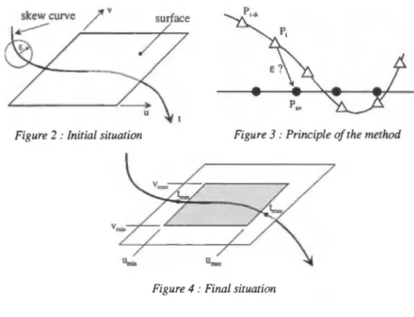
5. PRINCIPLE OF THE METHOD
The result of the search of intersection is defined for a given precision E. The result
given by the algorithm should be understood as follows: inside a sphere of radius E.,
it exists at least two points, one belonging to the curve and the other to the surface.
Each of the involved parameters, that is t for the curve, and u and v for the surface,
is then discretised. The obtained increments dt, du and dv depend on the precision E.
[7]. The boundaries of the parameterised areas can be determined after a fust rough
sorting using a hierarchical approach for example.
Subsequently, P, will designate the point of the curve associated to the parameter
t, and P11v the point of the surface associated to the parameters (u, v). The curve is
used as a support for the search (see figme 2).
For each discretised value of the parameter t, the surface is swept, and to each
couple (u, v ), the distance P,P11 ., is calculated (see figure 3). If this distance becomes
smaller than the precision E. , parameters t, u and v are stored in memory (these are
told "initial parameters").
Values of parameters are then increased. As soon as the distance becomes bigger
than E. , parameters are stored again in memory (these are told "terminal
parameters"). Thus, some potential intersection areas between the two geometrical
entities can be exhibited (see figure 4). It is then possible to proceed to a new
scanning of these areas, with a new precision smaller than E. . The operation is
Figure 2 : Initial situation Figure 3: Principle of the method
Figure 4 : Final situation
6. IMPLEMENTATION IN SAMCEF
First of all, the method of search of contact with the use of spline functions has been implemented in the finite element code Samcef [8].
It was not possible to develop directly within the source files of the code. So our developments have been realised via the user element which is a fortran routine compiled with the totality of the code. The user element allows the user to include in the code some elements he can set all the characteristics (number of nodes, degrees of freedom, constitutive law).
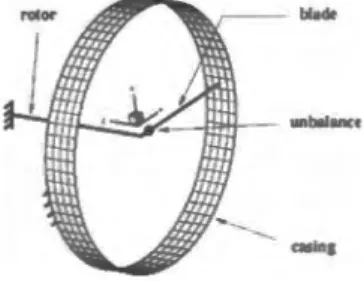
In the present case, the user element developed by I. Guilloteau [9] has been used: it concerns a simplified element of contact, using a modified penalty method. In its formulation, the search of contact uses geometrical entities of degree 1 built on finite elements. These entities are parts of the shells approximating plans for the casing, and segments for the blades. Thereafter, this method will be designated under the term "classic method". This classic search is therefore replaced by the method of search with spline modelisation. The test we use consists to simulate the rotation of an unbalanced blade inside a casing. The blade is represented by a generalised spring, and the casing (part of a cylinder clamped at its basis) is modelised by shells of Mindlin. The mesh is represented on figure 6.
This test is used to observe the value of the normal force on the blade tip during the contact, and the CPU time to simulate 5 rotations of the blade. The varying parameters are on the one hand the choice of the method of search of the contact (classic, splines of interpolation and by smoothing splines) and on the other hand the number of elements used to discretise the circumference of the casing (three
configurations have been studied: 72, 36 and 18 elements).
Figure 6: General view of the mesh
7. SAMCEF RESULTS
The first presented results concern the contact force : these results are normalised with respect to the maximal amplitude of the first contact force obtained with a method of interpolation in the 72 element configuration. It can be observed on figure 7 (72 elements in the circumference of the casing) that spline methods give very similar results with regard to the maximal amplitude of the force of the first contact (the difference between the methods is approximately 3%).
- -Cb.5iiC ----···--slfll)()(h!ng
~
llllCIPQlllll(D..
(
.. ~j \
··.e
] J!\
~
'I!
iI
l
g \i'
I
!I
\
I:
.,
...
Figure 7: Configuration with 72 elements
- real radius
fictive radius
(FE approximation)
Figure 8 : Finite element approximation
With a classic method, the radius of the casing is systematically underestimated (see figure 8). As a consequence the contact force whose calculation depends here on the radial penetration is always overestimated. In the present case, the contact force is about 30% bigger than the force given by a spline method. Moreover, the finite element approximation involves an early detection of the instant of the first contact (t
=
4 ms for the classic method and t=
6 ms with a spline interpolation).When the number of elements used to define the circumference of the casing decreases, these two problems greatly emphasize. When just 18 elements are used for example (see figure 9), the classic method detects a strong initial penetration that induces an amplitude of the first contact force twice bigger than the one obtained with a spline interpolation.
,,
..
~~~~~.~~~~~rimr(!r;)
Figure 9 : Configuration with 18 elements Figure 10 : Interpolation method
By representing on a same figure the results given by the three configurations (72,
36 and then 18 elements in the circumference of the casing), it is interesting to note
that the interpolation spline method is very little sensitive to the fineness of the mesh
concerning the amplitude ofthe first contact force peaks (see figure 10).
The second series of results focuses on the required CPU time to simulate 5
revolutions of the blade. All CPU times presented on figure 11 are normalised with
respect to the required CPU time with 72 elements and the classic method.
It appears that spline methods are more expensive than the classic method
(approximately 25% of supplementary time in the configuration with 72 elements),
what was expected due to the iterative scheme that is used for the search of contact.
However, it is important to note that a spline interpolation method with 36 elements
requires less CPU time (approximately 30%) than the classic method with 72
elements, while providing a comparable result.
,,
..
.
·~ 04=
01..
U" jlo< ~ 0~ E o• ~..
-
~
- da.'"Jc smoollnxI
=
lnttrpol>lionI
12 36 '8Figure II : CPU time comparison
8. IMPLEMENTATION IN PLEXUS
The method of contact search with splines functions has then been implemented in a
rapid dynamic finite element code named Plexus [5] which uses an explicit
formulation. In this code, it has been possible to develop directly in source files of
the code (a specific instruction has been created that allows, in the data set, the
selection of this kind of contact search).
of facetisation we are concerned with were faced, namely the problem of taking into account the curvatures of the structures, and the problem of discontinuity of the normal vector.
This test consists of a plate (the blade) sent with an initial translation velocity V0
onto the wall of a cylinder (the casing) clamped to its extremities (see figure 13). No particular boundary condition is attributed to the blade (all the dofs are free), and the problem is thus symmetric.
Elements used to mesh the blade and the casing are shells Q4GS [10]. The mesh is realised such that the blade is directed to impact a ridge of a shell (see figure 14).
r
-
x
Figure 13 : General view of the test Figure 14: Mesh top view
The result which is observed is the evolution of the contact force. In this explicit formulation, the contact force is calculated according to the relative position (local coordinates) of impacting nodes within impacted facets. The search of contact
existing in Plexus is a slipping line and surface method [11]: slave nodes and master
elements are matched, and the contact force is calculated with a kinematic formulation involving the local coordinates of nodes transgressing the criterion of contact in impacted elements. This method will be later on designated as the "classic method".
The results we present are related to the amplitude of the contact force in the two
directions
x
andy
.
First of all in the directionx
of impact (called "normal force"), it can be observed that the force given by the classic method is quite perturbed (see figure 15) while the force given by the spline method is quite regular.Figure 15: Normal force
~ u .!!
1
.~...
~~~·]
Q c_, lime(s) Figure 16: Tangential forceDue to the symmetry of the problem, no force is expected in the tangential direction
y .
However one can observe a non-zero force (called "tangential force") with a classic method, since it has an amplitude hardly three times smaller than the one in the normal direction (see figure 16). A spline method also provides a non-zero force, but with a very weak amplitude (more than 100 times smaller than the normal force).The very perturbed results provided by the classic method can be explained by the difficulty that exists to choose the reprojecting element when contact occurs: depending on the time step, and with the notations of figure 17, the reprojection will be made sometimes on the facet 1 and sometimes on the facet 2. The normal vectors of these two facets being very different, the values of contact forces are also very distinct. casing/ blade~ .. · - - - - : '·· ? ?
Figure 17: Problem of reprojection
This problem does not exist with the spline interpolation, since the normal vector is perfectly continuous in all the area of definition of the surface.
9. CONCLUSION AND PROSPECTS
The presented method aims at dealing with problems of facetisation when finite element codes are used to simulate some non-linear movements between structures.
The developments realised in two different finite element codes show that the time required for the search of contact points is bigger than the time required when using a classic method, but can be compensated by the given possibility to work with a reduced size mesh.
Under way developments aim at testing this method on some more complex problems (rotation of a transmission shaft in a bearing support for example) for which some programming difficulties will have to be faced (management of strong tangency areas that can considerably increase the time of calculation for example).
Applications of this method to other configurations except that of blade/casing contact studies are considered such as the use for stamping problems and the simulation of thermoforming (studies are being proceeded in our laboratory). Acknowledgements : The authors would like to deeply acknowledge the CEA (the French Nuclear Department), and especially H. Bung for the help provided in the Plexus implementation.
Etienne ARNOULT
Bernard PESEUX
Jerome BONINI
10. AFFILIATIONS
Universite de Technologie de Compiegne
Laboratoire Roberval- UMR UTC CNRS 6066 Rue Personne de Roberval
60200 COMPIEGNE- FRANCE Etienne.Arnoult@utc.fr Ecole Centrale Nantes
Laboratoire Mecanique et Materiaux BP92101
44321 NANTES Cedex 03- FRANCE Bernard.Peseux @ec-nantes. fr SNECMA
Centre de Villaroche Departement Methodes
77550 MOISSY CRAM A YEL- FRANCE Jerome. Bonini @snecma.fr
11. REFERENCES
[I] De Boor C., "A practical guide to Splines", vol. 27 of Applied Mathematical Sciences. Springer Verlag, 1978.
[2] Nurnberger G., "Approximation by spline functions", Springer Verlag, 1989.
[3] Daniel M., "Modelisation de courbes et surfaces par des B-splines- Application
a
Ia conception eta
Ia visualisation de formes", PhD Thesis, Ecole Nationale Superieure de Mecanique, Nantes, May 1989.[4] Hallquist)., "LS-DYNA3D, Theoritical manual", Dynalis, 1995. [5] CEA, "PLEXUS: Theoritical manual", 1997.
[6] Cescotto S., "Contact quasi-statique: resolution avec regularisation", in Moctelisation mecanique et numerique du contact et du frottement, !PSI, pp. 251-256, Paris, 15-17 oct. 1996.
[7] Arnoult E., "Modelisation numerique et approche experimentale du contact en dynamique: Application au contact aubes/carter de turboreacteur", PhD Thesis, University of Nantes, January 2000.
[8] Samtech, "SAMCEF, User manual", version 7.1, 1997.
[9] Guilloteau 1., "Modelisation du contact en dynamique: construction d'un element simplifie de contact et application
a
!'interaction rotor/stator", PhD Thesis, University of Nantes, November 1999.[10] Batoz J. & Dhatt G., "Modelisation des structures par elements finis", vol. 3 -"Coques", Hermes, 1990.
[11] Bonini J. & Bung H., "Modelisation des problemes de contact-impact avec frottement en explicite par Ia methode des multiplicateurs de Lagrange", in Actes du Troisieme Colloque National en Calcul des Structures, vol. I, pp 411-416, CSMA, Giens (France), 20-23 May 1997.