HAL Id: hal-01373423
https://hal.archives-ouvertes.fr/hal-01373423
Submitted on 28 Sep 2016HAL is a multi-disciplinary open access
archive for the deposit and dissemination of sci-entific research documents, whether they are pub-lished or not. The documents may come from teaching and research institutions in France or abroad, or from public or private research centers.
L’archive ouverte pluridisciplinaire HAL, est destinée au dépôt et à la diffusion de documents scientifiques de niveau recherche, publiés ou non, émanant des établissements d’enseignement et de recherche français ou étrangers, des laboratoires publics ou privés.
Experimental experience with Host Identity Protocol
(HIP)
Nahla Abid, Maryline Laurent, Hakima Chaouchi
To cite this version:
Nahla Abid, Maryline Laurent, Hakima Chaouchi. Experimental experience with Host Identity Protocol (HIP). [Research Report] Dépt. Logiciels-Réseaux (Institut Mines-Télécom-Télécom Sud-Paris); Services répartis, Architectures, MOdélisation, Validation, Administration des Réseaux (Insti-tut Mines-Télécom-Télécom SudParis-CNRS). 2008, pp.58. �hal-01373423�
Experimental experience with
Host Identity Protocol (HIP)
Softwares-Networks Nahla ABID *08014-LOR* Maryline LAURENT-MAKNAVICIUS 2008
Experimental experience with Host Identity Protocol
—oOo— Abstract
In the current Internet architecture, IP addresses play a dual role. On the one hand, they permit the identification of hosts in the network, and on the other hand, they serve as routing information. This role is becoming more and more problematic especially with the new requirements of mobility and multi-homing. HIP (Host Identity protocol) defines a new protocol between the network and transport layers in order to provide a better management to those requirements. The protocol defines a new namespace based on cryptographic identifiers which enable the IP address roles dissociation. Those new identifiers identify hosts rather than IP addresses. Because HIP is a quite recent protocol, we propose to present an experimental evaluation of its basic characteristics. Key-words: Host identifier, namespace, layer, roles dissociation, HIP, experimenta-tion.
R´esum´e
Dans l’architecture Internet actuelle, les adresses IP jouent un double rˆole. D’une part, elles permettent d’identifier les hˆotes dans le r´eseau, et d’autre part, elles servent comme une information de routage. Ce rˆole devient de plus en plus probl´ematique surtout avec les nouveaux besoins de mobilit´e et multi-homing. HIP (Host Identity Protocol) d´efinit un nouveau protocole entre la couche r´eseau et transport pour fournir une meilleure gestion de ces besoins. Le protocole d´efinit un nouvel espace de nommage bas´e sur des identifiants cryptographiques qui permet de dissocier les rˆoles des adresses IP. Ces nouveaux identifiants jouent le rˆole d’identifiants d’hˆotes au lieu des adresses IP. Vu que HIP est un protocole assez r´ecent, on propose de pr´esenter une ´evaluation exp´erimentale de ses principes de base.
Mots-cl´es : identifiant d’hˆote, espace de nommage, couche, dissociation de rˆoles, HIP, exp´erimentation.
—oOo—
Nahla Abid Maryline Laurent-Maknavicius Hakima Chaouchi Stagiaire Professeur Maˆıtre de conf´erence
TELECOM & Management SudParis - LOR Department 9 street Charles Fourier 91011 Evry cedex
{Nahla.Abid|Maryline.Maknavicius|Hakima.Chaouchi}@it-sudParis.eu
Contents
Introduction
8
1 Internet Namespaces Problematic 9
1.1 Introduction . . . 9
1.2 Current Internet architecture and problem delimitation . . . 9
1.2.1 Dual role of IP addresses . . . 10
1.2.2 Problem statement . . . 10
1.3 The Host Identity Protocol (HIP) solution . . . 10
1.3.1 A new namespace . . . 11
1.3.1.1 Host Identity Tag (HIT) . . . 12
1.3.1.2 Local Scope Identity (LSI) . . . 12
1.3.2 A new layering architecture . . . 12
1.4 Conclusion . . . 14
2 The Host Identity Protocol: Description 15 2.1 Introduction . . . 15
2.2 HIP based communications . . . 15
2.2.1 HIP packet format . . . 16
2.2.2 HIP Base Exchange . . . 18
2.2.2.1 I1 packet . . . 18
2.2.2.2 R1 packet . . . 19
2.2.2.3 I2 packet . . . 21
2.2.2.4 R2 packet . . . 23
2.3 HIP and Name Resolution . . . 24
2.3.1 Two name resolution approaches . . . 24
2.3.2 BE in the presence of a RVS . . . 25
2.4 Usage of IPsec by HIP . . . 26
2.4.1 Creating Security Associations . . . 26
2.4.2 Updating SAs . . . 27
2.5 Mobility and Multi-homing in HIP . . . 28
2.5.1 Mobility with HIP . . . 28
2.5.2 Multi-Homing with HIP . . . 29
2.6 Current HIP development . . . 30
2.7 Conclusion . . . 31
3 Tests Scenarios Description 32 3.1 Introduction . . . 32
3.2 Project goal . . . 32
3.3.1 TEST SCENARIO A: BE Time Measurement . . . 33
3.3.2 SCENARIO B: Influence of puzzle difficulty . . . 36
3.3.3 SCENARIO C: RTT (Round Trip Time) measurements . . . 37
3.3.4 SCENARIO D: Throughputs measurements . . . 38
3.3.5 Scenario E: Duration of mobility procedure . . . 39
3.4 Tests environment and set-up . . . 39
3.4.1 Tests tools and Software . . . 39
3.4.1.1 Hardware specifications . . . 39
3.4.1.2 HIPL . . . 40
3.4.1.3 TCPDump tool . . . 40
3.4.1.4 Wireshark (previously called Ethereal) . . . 40
3.4.1.5 Iperf tool . . . 41 3.4.2 Tests Execution . . . 41 3.4.2.1 Scenario A . . . 41 3.4.2.2 Scenario B . . . 43 3.4.2.3 Scenario C . . . 43 3.4.2.4 Scenario D . . . 44 3.4.2.5 Scenario E . . . 44 3.5 Conclusion . . . 44
4 Tests Results and Evaluation 46 4.1 Introduction . . . 46
4.2 Tests Results . . . 46
4.2.1 Scenario A – BE time measurement . . . 46
4.2.2 Scenario B – Influence of puzzle difficulty . . . 49
4.2.3 Scenario C – RTT measurements . . . 50
4.2.4 Scenario D – Throughputs measurements . . . 51
4.2.5 Scenario E - Duration of mobility procedure . . . 52
4.3 Tests evaluation . . . 52
4.4 Conclusion . . . 54
Conclusion
55
Bibliography 57
List of Figures
1.1 Identity and location roles separation . . . 11
1.2 Comparison between HIP model and the traditional model . . . 13
1.3 Comparison between current bindings and HIP bindings . . . 13
2.1 HIP packet format . . . 16
2.2 HIP Base Exchange procedure . . . 18
2.3 I1 HIP packet . . . 19
2.4 R1 HIP packet . . . 20
2.5 I2 HIP packet . . . 22
2.6 R2 HIP packet . . . 23
2.7 Name Resolution in HIP with and without RVS . . . 24
2.8 Initiator’s and Responder’s SAs pair . . . 26
2.9 HIP Base Exchange combined with HIP ESP Setup Protocol . . . 27
2.10 Updating an existing ESP SA . . . 28
2.11 HIP mobility procedure . . . 29
2.12 Multi-homing scenario with HIP . . . 29
2.13 OpenHIP project logo . . . 31
2.14 InfraHIP project logo . . . 31
3.1 Times measured in A1, A2 and A3 sub scenarios . . . 35
3.2 Nokia N800 Tablet . . . 40
3.3 HIP packets captured by Wireshark . . . 41
3.4 Sub scenario A1 network . . . 42
3.5 Sub scenario A2 network . . . 42
3.6 Sub scenario A3 network . . . 42
List of Tables
2.1 HIP packet types . . . 17
3.1 Sub scenarios A1, A2 and A3 characteristics . . . 34
3.2 Sub-scenarios B1 and B2 characteristics . . . 37
3.3 Sub scenarios C1 and C2 characteristics . . . 37
3.4 Sub scenarios D1 and D2 characteristics . . . 38
3.5 Sub scenarios E1 and E2 characteristics . . . 39
4.1 Scenario A – BE time measurements(ms) . . . 46
4.2 Scenario A - BE time measurements(%) . . . 47
4.3 Test scenario B results – T2 measurements(ms) . . . 49
4.4 Test Scenario C results - RTT measurements(ms) . . . 50
Introduction
Few decades ago, when Internet was designed, the fundamental goal behind this pro-posal was simply the effective network interconnection. Using its two basic namespaces, DNS names and IP addresses, founded on the traditional TCP/IP stack and having static and one-homed hosts, Internet succeeded perfectly and for a long time to cover all its users’ needs.
Step by step, new requirements appear on the surface and the Internet user nowadays is no longer the same one as decades ago. Recent unprecedented growth of the mobile technology market, devices support for more than one of a myriad of technologies and operators and the need to communicate from anywhere and at any anytime are the chal-lenges of nowadays networks.
Needs are evolving and users are more demanding. Using Internet with the traditional considerations of decades ago is no more appropriate and sufficient. Sticking to its tradi-tional architecture, Internet is no longer able to cover all its user needs especially mobility, multi-homing and security ones.
Few new Internet generation solutions were proposed last years as attempts to solve this problematic. However, their success was partial and limited for two reasons. First of all, those solutions can be described by ‘tiny’ ones since they were too specialized. For instance, MobileIP (MIP) focuses mainly on mobility issues, IPsec is addressing only security issues,. . . All of them look to the problem from one side and none of them treated it as a whole one. Secondly, all the provided solutions were based on the traditional TCP/IP stack and tried just to adapt it.
But, what benefit could it be if we look differently to current Internet problems? If we try to solve the problem radically and deeply? If we adopt a solution that does not settle to what we have, but rather explores new axes?
The Host Identity protocol (HIP) is a recent protocol proposal at the IETF that comes to reply to all those questions and provides a complete solution to all those problems,
enabling mobility, multi-homing in a secured way. HIP introduces a new namespace, Host Identity namespace and a new layer, Host Identity layer. The protocol specifies also a secured way to establish HIP based communications and how it solves the mobility and multi-homing issues.
The IETF provided a full theoretical description of the main features of the protocol. Those specifications are supported by many projects working on implementing the proto-col. Because the protocol is quite recent, going through its experimental evaluation seems to be interesting and very beneficial to give some conclusions about its performances.
The idea of our project turns around that point. In fact, the present work consists in an experimentation of HIP basic features. Different types of scenarios were performed in order to evaluate the basic characteristics of HIP. The goal of the project is to achieve providing some practical results about HIP.
This report was written in order to describe the context of our work and to present the different results we obtained. It is organized into four chapters as follows.
Chapter 1 begins with an overview of the current Internet architecture and problem-atic. Then, we present how HIP can be a possible solution for those problems. Chapter 2 examines HIP into more details. The chapter presents HIP based communications along-side with the new packet format and parameters proposed by HIP. It looks also to the name resolution, mobility and multi-homing issues with HIP. In chapter 3, we provide a detailed presentation of the testing scenarios performed. This includes a description of the testing networks set up and the steps of execution. Finally, chapter 4 concludes the report by evaluating the results obtained from scenarios and giving some conclusions about HIP basic characteristics.
1
Internet Namespaces Problematic
1.1
Introduction
Chapter one provides all the fundamental technical background useful for the readers to understand the remainder of the report. This chapter covers basic topics related to the items of the project and is sub classified into two sections.
Section 2 is intended to make a survey of the present Internet architecture as well as the different problems. Section 3 gives a general overview of the Host Identity Protocol (HIP) as a promising solution and possible components of the next-generation Internet architecture.
Further details about the protocol specifications are given later in chapter 2.
1.2
Current Internet architecture and problem
de-limitation
Currently, two namespaces are used in the Internet architecture: the Domain Name Service (DNS) names [1] [2] and the Internet protocol (IP) addresses [3]. They serve as a basis for the development and large deployment of Internet working technology and were behind its success and flexible use for years.
The DNS namespace, hierarchical by nature, consists in establishing the mapping be-tween domain names used at application level of the ISO/OSI network model, and IP addresses used both at the same level and lower levels. However, IP addresses namespace plays a larger role in the Internet. In the following sections, we provide first a detailed description of this role, and then we show how this namespace is becoming more and more semantically overloaded especially with the increasing new needs that appear in nowadays networks.
1.2.1
Dual role of IP addresses
In the current Internet architecture, IP addresses play a dual role of locators and end-point identifiers.
In fact, from the network layer point of view, those addresses are used as routing information serving to identify the topological location of the hosts in the network. Thus, if a host moves, its location changes and consequently its IP address has to change too. This role is called the locator role of an IP address.
However, from upper layers point of view, IP addresses play a second role which is identifying the host itself during communications and connections. This role is referred to as the identifier role of an IP address. At that level, IP addresses are not supposed to change during a communication even if the host changes its location.
This is what we mean by ‘dual role of IP addresses’.
1.2.2
Problem statement
As the Internet evolved from its modest beginnings to a more complicated structure, new requirements appeared on the surface such as the increasing need of having mobile and multi-homed hosts everywhere. Unfortunately, Internet architecture, as it was conceived for a long time, is no longer able to meet those new needs for many reasons.
The most important problem of the present architecture is the dual role of IP addresses that we explained above. Having IP addresses serving to locate and identify hosts makes the current architecture less and less flexible toward the increasing needs of mobility and multi-homing. In other words, upper layer connections have to break down each time the mobile node changes its location. This is due to the fact that those connections are bound to IP addresses and thus they are affected by any changes in the network level.
Adding this to the case when the mobile node is also multi-homed makes the manage-ment of multiple and dynamic addresses at the same time harder than necessary.
1.3
The Host Identity Protocol (HIP) solution
Many thoughts have been developed in order to handle with this problematic. There-fore, many solutions have been proposed solving the problem from different points of view.
Decoupling the location from the identity seems to be the most straightforward solution. This idea was discussed, few years ago, in the IETF (Internet Engineering Task Force) [4]and IRTF (Internet Research Task Force) [5] and led to the proposal of a new protocol, named the Host Identity Protocol (HIP) [6] .
The fundamental idea of the protocol is simple: tackling the problem from the root by getting rid of this confusing and problematic role. In other words, HIP proposes to assign a new static ultimate identity to any host alongside with its location information where both of them are evolving in a totally independent way. As a result, the hosts will keep their identities unchanged even if they change their location over the network.
For this purpose, HIP specifies a new namespace for the Internet and a new layering architecture.
1.3.1
A new namespace
Along with the two existing namespaces used till now in the Internet and in order to achieve this separation of roles, HIP proposes the use of a third cryptographic-based namespace, called the ‘Host Identity’ (HI) namespace [6].
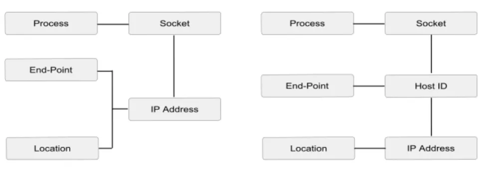
Figure 1.1: Identity and location roles separation
As displayed in Figure 1.1, IP addresses use becomes reduced to the network layer level as location information while the new HI operates in all the upper layers to identify the end-point.
A host identity is an asymmetric public/private key pair. The public key part is desig-nated by the Host Identifier (HI) and it serves to uniquely identify the host in the network. However, the host itself is defined as the entity that holds the private key. Possessing this private key proves that the host owns really the identity represented by the public part.
A host identifier can identify only one host while one host can have simultaneously many host identifiers.
HIs are called ‘public’ ones when they are stored in DNS (see section 2.7). Thus they can be known by any host in the network. However, they can also be ‘anonymous’ ones, in which case they are known only by the communicating hosts.
Depending on the cryptographic algorithm in use (RSA, DSA. . . ), length of the HI might be different. That is why using the HI as it is in HIP based communications seems not practical at all. On the one hand, having a variable length for identifiers makes their usage difficult and totally dependent on the generation algorithm. On the other hand, it does not manage the packet size cost in an efficient way [7].
To solve this problem, two operational fixed-lengths representations of host identifiers are proposed: the Host Identity Tag (HIT) and the Local Scope Identifier (LSI) [6].
1.3.1.1 Host Identity Tag (HIT)
The HIT is a 128-bit SHA-1 hash of a host identifier. As it has the same length than an IPv6 address, it can be used for supporting IPv6 applications. Thus, applications can not detect any difference between a HIT and an IPv6 address.
1.3.1.2 Local Scope Identity (LSI)
The LSI is also a representation of a HI but with a smaller length than HITs fixed to 32 bits. It is rather used with IPv4 based applications. An LSI facilitates then, the use of the new namespace in existing applications.
1.3.2
A new layering architecture
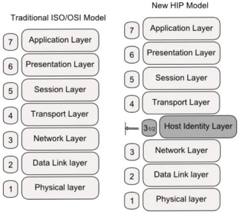
In addition to the new namespace introduced, HIP proposes some modifications to the traditional ISO/OSI networking model. In fact, HIP introduces a new layer, the ’host identity layer’ [6], between the network and the transport layers. The new HIP model is shown in Figure 1.2.
Figure 1.2: Comparison between HIP model and the traditional model
The role of this new layer is to make the mapping between HIs used in upper layers and IP addresses.
However, the changes introduced by HIP are more than an additional layer, they also enclose all the upper layers connections. For more understanding of this point, let us make a brief comparison between the traditional and the new architectural bindings.
Current Internet traditional bindings are shown in the left illustration of Figure 1.3. Transport connections are identified by pairs of IP addresses and ports. Thus if the IP address changes in a mobility scenario for example, the upper layer connections are affected and have to be reinitialized with the new addresses. This makes the network and upper layers very dependent. No one can evolve separately from the other.
Differently, from a HIP point of view (right illustration of Figure 1.3), those connections are no longer bound to IP addresses but rather to the new identities, i.e. the HIs. This makes the identification of end-point hosts in any HIP based communication independent from the location information. IP addresses are used only in the networking level as routing information. Therefore even if the host moves, the mobility becomes transparent to upper layers.
This clarifies the basic idea behind HIP: separating location and identification roles.
1.4
Conclusion
In this chapter, we introduced the coming parts of the report by setting the context of our work domain: HIP as a new protocol for the future Internet.
Underlying the importance of separating identity from location in networks architec-tures, understanding the idea behind the new Host Identity namespace proposed by HIP and looking at the new HIP model were the main objectives of the first chapter. Having all that in mind, we are now ready to go through more details about HIP in the second chapter.
2
The Host Identity Protocol:
Description
2.1
Introduction
This chapter examines HIP in more details and discusses relevant features related to the new protocol.
Section 2 highlights the HIP based communications underlying the new packet format proposed as well as the new way to establish a HIP communication between hosts. In section 3, we underline the secured part of HIP mainly in exchanging data. Section 4 discusses mobility and multi-homing management with HIP. Finally, section 5 makes a look at the current development of HIP.
2.2
HIP based communications
Alongside with the new architectural concepts proposed by HIP and stated above in chapter one, hosts communications are modified as well in a HIP way taking into account the new namespace and layer.
Obviously, the new protocol specifies a different way for establishing HIP based com-munications and proposes for this a new packets type, the HIP packet one. If two hosts, HIP enabled of course, want to communicate using HIP, two phases are needed for that: the HIP Base Exchange [7] and the secured data transfer [8].
The first phase, i.e. the HIP Base Exchange (BE), consists in a four-way handshake based on the exchange of HIP packets between the host who triggers the communication, referred to as the initiator, and its peer host designated by the responder. The main purpose of the BE is to establish what we call a HIP association between the initiator and the responder. This step permits the mutual-authentication of the two end-points using their HITs or LSIs, and a negotiation of certain security parameters that will be used later in the data transfer.
After the BE is finished and the HIP association is established, the two hosts are ready to begin the second phase of data exchange in a secure manner.
Before going through the details of each phase, we suggest that we present first the format of a HIP packet as specified in [7]. At this level, this seems mandatory to be able to understand the rest of the document.
2.2.1
HIP packet format
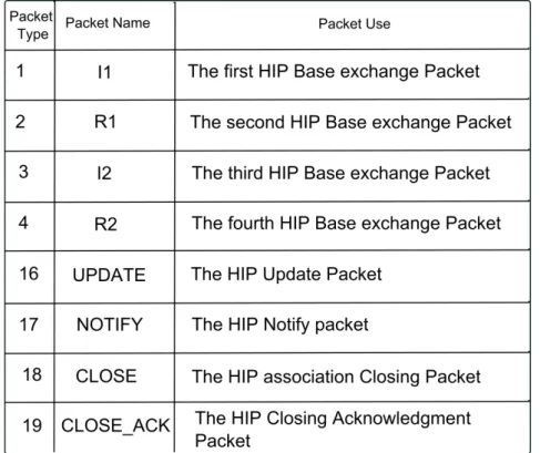
In the protocol specification [7], eight HIP packet types were proposed, as follows:
• I1, R1, I2 and R2 are the four packet types used in the phase of BE. The details of those 4 packets are more detailed in 2.2.2.
• UPDATE packets are used to update the HIP association between the two hosts for example in situations of mobility, multi-homing or updating the security associ-ations.
• NOTIFY packets whenever the host needs to provide information to its peer.
• CLOSE, CLOSE ACK packets are used to close a HIP association.
Figure 2.1 illustrates the structure of a HIP packet, which remains the same whatever the type of the packet.
Here below, we propose a brief description of each field of the HIP header:
• Next header ( 8 bits ): It corresponds to the next header field in IPv6 protocol specification. Its value is fixed to 59 in decimal which matches ‘ no next header ‘ in IPV6.
• Header length ( 8 bits ): It indicates the total length of the HIP packet in a 8-byte unit excluding the first 8 8-bytes of the packet header, i.e. starting from the field sender’s HIT. Its minimum value is 4 in the case of HIP packets with no parameters.
• Packet type ( 7 bits ): It indicates the HIP packet type. Table 2.1 indicates the mapping between the packet names and types.
Table 2.1: HIP packet types
• Version ( 4 bits ): It determines the version number of HIP. Currently it is set to one.
• Reserved ( 3 bits ): Those bits are reserved for future use and should be set to zero.
• Checksum ( 16 bits ): It has to be recomputed for different lower layer protocols (IPv4 or IPv6)
• Controls ( 16 bits ): It carries additional information about the packet such as the anonymity of HI for example.
Alongside with the fixed HIP header described above, a HIP packet may transport certain HIP parameters depending on the type of the packet. Later sections provide a brief description of each parameter when needed or used.
2.2.2
HIP Base Exchange
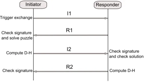
It works as a four-way handshake between the two hosts [7], Initiator and Responder. The main purpose of the Base Exchange is to create a communication context, named HIP association, between two end-hosts. It supports mutual authentication based on public/private keys of hosts, symmetric D-H key agreement and DoS (Denial of Service) prevention mechanism.
Figure 2.2: HIP Base Exchange procedure
2.2.2.1 I1 packet
As depicted in Figure 2.2, the initiator triggers the communication by sending the I1 packet to the responder. The I1 packet is the first packet in the BE. Its structure is shown in Figure 2.3.
Figure 2.3: I1 HIP packet
In fact, this packet is the only BE packet transmitted in the network unsigned and encrypted. As we see in the Figure 2.3, the packet type field is set to one which corresponds to the type specified for I1’s packets. In addition, the header length field value is fixed to four , minimum value of the field, since the I1 packet contains only the fixed header and carries no more additional HIP parameters. The sender’s HIT field carries the initiator’s HIT, however the receiver’s one can transport either the responder’s HIT or NULL value (all zero) if the responder’s HIT is unknown for the initiator. This latter case is referred to as the ” HIP opportunistic mode”.
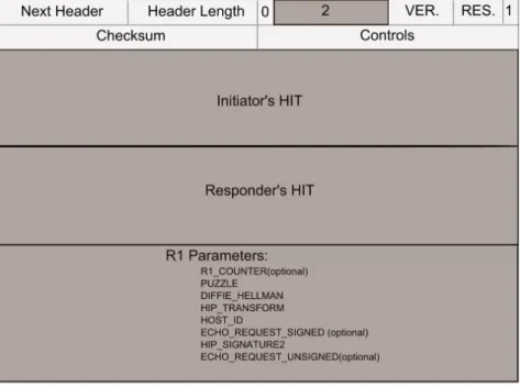
2.2.2.2 R1 packet
Once receiving the I1 packet, the node begins by verifying if the receiver’s HIT corre-sponds to one of its HITs or NULL. If it is the case, it has the choice to deny or accept to establish the HIP association. In the first situation, an ICMP message ‘Destination Unreachable, Administratively Prohibited’ should be sent to the initiator. However in the second situation of acceptance, the node called from now on the responder has to respond with an R1 packet.
Such packet can be instantaneously almost newly created when receiving the I1 packet or selected from pre-computed ones.
Figure 2.4: R1 HIP packet
As depicted in Figure 2.4, an R1 packet corresponds to HIP packet type 2. It carries the HITs of both the responder and initiator respectively in sender’s and receiver’s HIT fields. We are going to list the set of HIP parameters that can be contained in R1 packet giving a brief description of each one.
• R1 COUNTER parameter: Its presence in the R1 packet is optional but once existing, it has to be echoed by the initiator in I2 . As its name shows, this parameter carries a counter that indicates the valid puzzle solutions that the responder may accept. All puzzle solutions corresponding to inferior value of R1 COUNTER are no more taken into consideration by the responder. An R1 COUNTER value is periodically incremented.
• PUZZLE parameter: It corresponds to a cryptographic challenge proposed by the responder and expected to be solved by the initiator in order to continue the BE. The goal behind such a mechanism is to avoid Denial of Service attacks. In fact, the principle of the puzzle requires that the time spent by the initiator to solve it is far longer than the time needed by the responder to verify later the validity of the solution. Briefly, the puzzle consists of a random number #I and a difficulty K that the responder sets depending on the level of trust between the two hosts. Solving a puzzle consists in finding a number #J verifying the following: The lowest order K bits of the hash applied to the concatenation of #I, the two HITs of the parties and #J are equal to zeros. The hash function used is based on the RHASH algorithm.
(D-H)values suggested by the responder .It permits to compute the Diffie-Hellman session key (Kij) and to create the keying material corresponding to the HIP asso-ciation. The initiator has to choose one of the proposed D-H values.
• HIP TRANSFORM parameter: it can carry from one to six encryption and integrity protection algorithms supported by the responder. The initiator has to choose again one of the proposed algorithms.
• HOST ID parameter: It corresponds to the HI of the responder .In the case of anonymous HI, the HIP controls field in R1 packet should be set to “A” value.
• ECHO REQUEST SIGNED parameter: Like the R1 COUNTER parameter, ECHO REQUEST SIGNED is optional. It carries some data that the responder expects the initiator to echo it in an ECHO RESPONSE SIGNED parameter.
• HIP SIGNATURE 2 parameter: It contains the result of R1 packet signature. Note that during the signature, the destination HIT, the checksum field, the #I puzzle random number and opaque fields are temporarily set to zeros. This allows the responder to pre-compute R1 packets before even receiving I1 packets. The rest of the R1 packet missing fields is completed once receiving an I1 packet.
• ECHO REQUEST UNSIGNED parameter: It has the same role than the ECHO REQUEST SIGNED parameter with the following differences. On the one hand, an R1 packet can contain one or more ECHO REQUEST UNSIGNED pa-rameter while it can carry only one ECHO REQUEST SIGNED papa-rameter. On the other hand, this parameter, as its name indicates, is not covered by the packet signature.
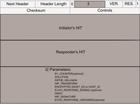
2.2.2.3 I2 packet
After receiving the R1 packet, the initiator begins by verifying that it has really sent an I1 packet to the corresponding HIT. If it is the case, the second step to do consists in verifying the received packet signature validity using the public key of the host Identifier, contained in HOST ID parameter. At that time the initiator responds with an I2 packet structured as described in Figure 2.5.
Figure 2.5: I2 HIP packet
HIP packet type 3 has been assigned to I2 packets. The HITs fields carry as usual the corresponding HITs. The HIP parameters that may be present in this packet are the following:
• R1 COUNTER parameter: It must be present in this packet if it has been already given in the corresponding R1 packet. In that case, it has to carry the same value.
• SOLUTION parameter: It contains the puzzle solution that the initiator has calculated.
• DIFFIE HELLMAN parameter: It contains the Diffie-Helman parameters cho-sen from the ones proposed in the same field in the R1 packet. At this level and with those parameters, the initiator has already calculated the public D-H key (Kij) and generated the HIP keying material that will be used later in any encryption algorithm.
• HOST ID parameter: It carries the initiator HI encrypted using the encryption algorithm chosen from the ones proposed in the HIP TRANSFORM parameter in R1.
• ECHO RESPONSE SIGNED parameter: It must be present in the packet if an ECHO REQUEST SIGNED parameter has been present in R1. In that case, it must echo the same data.
• HMAC parameter: It carries a keyed-hash message authentication code (hmac) covering all the HIP packet. Its role is to provide the integrity protection of the packet.
• HIP SIGNATURE parameter: It contains the HIP packet signature covering all the HIP packet.
• ECHO RESPONSE UNSIGNED parameter: It echoes the ECHO REQUEST UNSIGNED parameter that may be present in the R1 packet.
2.2.2.4 R2 packet
After receiving an I2 packet, the responder decrypts the initiator’s HI and verifies the HMAC and HIP SIGNATURE values. Then, it begins creating the R2 packet. This packet is the last packet in the BE and it responds the I2 one (cf. Figure 2.6).
Figure 2.6: R2 HIP packet
The packet type in this case is equal to 4. R2 packets contain two parameters which are the following:
• HMAC 2 parameter: It corresponds to a HMAC calculation over the HIP packet but taking into account a pseudo Host ID field.
2.3
HIP and Name Resolution
2.3.1
Two name resolution approaches
In order to support the introduction of the new namespace of Host Identity in the Internet, name resolution in current architecture, has to undergo some modifications. In fact, domain names are presently resolved to IP addresses using the DNS. This latter ensures the translation of internet names, easier to remember and use, into IP addresses used by networking devices.
Figure 2.7: Name Resolution in HIP with and without RVS
Adding the mapping between those names and HIs becomes obviously essential to support HIP based communications. For this purpose, HIP defines a new resource record (RR) for the DNS and two approaches on how to handle the name resolution [9]. The first approach, as shown in the left illustration of Figure 2.7, simply stores in addition to the host IP address (es) its Host Identity and HIT(s). Thus, when a host is looking up an FQDN, DNS replies with the corresponding host IP address(es),its HI and HIT(s) depending on the type of the query performed.
The problem of this solution occurs in mobility scenarios. In such situations, the host needs to frequently update its location information in DNS. However, the structure of DNS as it has been designed, enables it to update immediately its records. This causes a problem of latency totally inappropriate with the mobility requirements.
For this reason, HIP introduces a new mechanism, called the Rendez-Vous Server (RVS) [10], responsible for making the mapping between IP address(es), HIs and HITs. The main
advantage of a RVS is its ability to update its records, and thus the network information, within a short time. This makes its use suitable with the increasing need of mobility.
Each host in the network has to register to one or more RVS referring to the mechanism described in [10]. And each time the host changes one of its IP address (es), it has to inform it(s) RVS to keep it (them) updated with the new changes.
Referring to this approach, the new RR in the DNS contains this time additionally the domain names and IP address of the corresponding RVS.
When a host is looking up a mobile node in the DNS, it gets the HI and HIT(s)of the mobile node and the IP of its RVS.
Note that the use of RVS affects also the way in which a BE is performed.
2.3.2
BE in the presence of a RVS
A RVS becomes the point on which all its hosts are reachable from the network. This is why if the responder host in a BE is registered to a RVS, the initiator has to contact the RVS first.
In other words and as described in the section before, the initiator looks up the re-sponder’s FQDN in DNS. As a result, it gets the HI, HIT(s) and corresponding RVS IP address. The first message in the four way handshake (I1) passes through the RVS, and is no longer sent directly to the IP address of the responder.
However, the rest of the HIP messages (R1, I2 and R2) are communicated directly between the two hosts as shown in the right illustration of Figure 2.7.
This introduces obviously some modifications to the I1 packet structure described in section 2.2.2.1.
In fact, when receiving an I1 packet, a RVS checks that the HIT contained in the receiver’s HIT field of the packet header matches one of the HITs of its nodes. If so, it replaces the destination IP address of the packet by one of the responder’s IP addresses, it recomputes the IP checksum. In addition, the source IP address of the packet is changed from the initiator IP address to the RVS IP address.
Two parameters are added by the RVS to the I1 packet parameters. The first one, the FROM parameter, is added in order to carry the initiator address. While the second one, RVS HMAC, is a HMAC calculated over the HIP packet in order to ensure the integrity of the information exchanged.
The first message in the four way handshake (I1) passes through the RVS, while the rest of the HIP messages (R1, I2 and R2) are communicated directly between the two hosts as shown in the right illustration of Figure 2.7.
2.4
Usage of IPsec by HIP
HIP enables the end-hosts to establish secured communications to exchange various types of data, once the Base Exchange phase is completed. For this purpose, HIP uses, typically but not necessarily, IPsec Encapsulating Security Payload (ESP) transport mode [8].
2.4.1
Creating Security Associations
A pair of security associations (SA), one for incoming packets and one for outgoing packets, is established between the two peers during the Base Exchange.
Figure 2.8: Initiator’s and Responder’s SAs pair
Each host defines its incoming association Security Parameter Index (SPI) while its outgoing SPI is defined by its peer. Referring to the example shown in Figure 2.8, the SA-IR and SA-RI are the two SAs that were established between the initiator and the responder. SPI I-R(respectively SPI R-I) is the SPI that the responder (respectively the initiator) choosed for its incoming SA, SA-IR (respectively SA-RI). However, its outgoing SPI SA is equal to SPI R-I (respectively SPI I-R) chosen by its peer host.
All the security parameters needed to set up those SAs are negotiated in the first phase of the communication. Thus, some changes applied to the Base Exchange messages presented in section 2.2.2 are defined to support this (cf. Figure 2.9).
ESP TRANSFORM and ESP INFO are HIP’s packet parameters mainly used for this purpose.
Figure 2.9: HIP Base Exchange combined with HIP ESP Setup Protocol
The ESP TRANSFORM parameter is sent in R1 by the responder indicating the ESP transforms that it may support.
In this case, the initiator has to select one of them and sends it in I2 in an ESP TRANSFORM parameter too. In addition to that, it defines its SPI value, sends it in the ESP INFO parameter and creates its incoming SA. The initiator outgoing SA is not created yet at this level of the BE, since its SPI has to be defined by the peer host and not by the host itself.
After receiving the I2 message, the responder uses the initiator SPI value to create its outgoing SA, defines its own SPI and creates its incoming SA. The responder SPI value is sent in R2 in ESP INFO parameter to enable the initiator to create its missing outgoing SA.
2.4.2
Updating SAs
A pre-existing security association between two hosts usually needs to be updated to maintain a good security level. UPDATE HIP messages are used for this purpose. A typical SA update procedure is described in Figure 2.10.
Figure 2.10: Updating an existing ESP SA
The host willing to update its SA sends its new SPI and old SPI values in the ESP INFO parameter with an optional DIFFIE HELMANN parameter, once a new keying material has to be generated. The receiver must reply with an UPDATE message that includes the old and new SPI values in the ESP INFO parameter, an optional DIFFIE HELLMAN parameter and an ACK parameter to acknowledge the first message. The rekeying is finalized by the last UPDATE message sent by the initiator.
In case of IP address change due to mobility or multi-homing, the ESP association between HIT is not impacted, and the remote node only has to check the reachability of the new IP address.
2.5
Mobility and Multi-homing in HIP
HIP uses UPDATE messages to support both mobility and multi-homing.
2.5.1
Mobility with HIP
When a mobile host modifies its location and thus its IP address, it sends an UPDATE message to its peers in order to inform them about this change [11]. The new IP address is carried in the LOCATOR parameter of the UPDATE message. Actually, in the mobility case, different cases are possible depending on the need of either the mobile host or its peer to rekey the ESP security association (SA).
Figure 2.11 displays a mobility scenario with a possible rekeying initiated by the mobile host.
Figure 2.11: HIP mobility procedure
The mobile node sends an UPDATE message containing its new locator (LOCATOR), a SEQUENCE NUMBER parameter (SEQ) to identify the order of UPDATE messages, the new and old SPIs values of the concerned SA carried in the ESP INFO parameter (ESP INFO) and possibly a new Diffie-Hellman key (D-H) if the mobile host needs to generate a new keying material. Note that both the old and new SPI are set to the same value of the pre-existing incoming SPI in the case of a simple readdressing scenario without rekeying. The peer acknowledges this message by sending another UPDATE message containing the previously used sequence number (SEQ), the old and new SPI values contained in the ESP INFO parameter, and an ECHO-REQUEST (ECHO-REQ) parameter containing a nonce used to verify the new address. This second message is sent to the new IP address of the mobile host. The mobile host completes the update procedure by sending an UPDATE acknowledgement (ACK) and echoing the nonce in an ECHO RESPONSE parameter (ECHO RES).
2.5.2
Multi-Homing with HIP
For the multi-homing scenario, it is also based on the use of UPDATE messages with the only one difference that the LOCATOR parameter carries here all the addresses of the multi-homed host. Figure 2.12 shows the messages exchange needed for the multi-homing scenario.
The multi-homed host announces its new address to its peer using the LOCATOR parameter of the UPDATE message. This parameter contains pairs of the host’s old addresses and their corresponding SPIs, as well as the new address and the new SPI generated for the inbound SA of this address. This latter SPI value is also carried in the new SPI field of the ESP INFO parameter, while the old SPI value is set to zero. Similarly to the mobility scenario, a SEQUENCE (SEQ) parameter and an optional new Diffie-Hellman key value are contained in this first UPDATE message. Note that in the presence of many addresses, it is mandatory that the multi-homed host indicates its preferred address in the PREFERRED LOCATOR field of the LOCATOR parameter.
After receiving this UPDATE message, the peer host first checks the ESP INFO pa-rameter, creates a new inbound SA as described in section and checks the reachability of the new address as mentioned above in the mobility scenario. If a new preferred address is proposed by the multi-homed host, the peer must also verify the reachability of this address before taking this change into consideration.
2.6
Current HIP development
Presently, the IETF HIP working group [4] and the IRTF HIP research group [5] work closely in order to develop all the features related to HIP trying to provide a complete specification of this new protocol. Those two bodies are responsible too for publishing the HIP related documents (drafts, RFCs, . . . ).
Referring to the documents published till now about HIP, the following features have been specified:
• HIP basic architecture [6]
• HIP based communications [7]
• Using the ESP Transport Format with HIP [8]
• HIP registration extension [12]
• HIP Rendez-Vous extension [10]
• HIP DNS extension [9]
• End-Host mobility and multi-homing with HIP [11]
In accordance with those entities, many groups are working on studying and implement-ing the protocol. There are mainly three open-source projects that have been developed in that purpose. We give a brief description of each one of them in the following.
• OpenHIP project [14]: Supported by the Boeing Company, this project worked since 2005 on developing reference implementations of HIP under different platforms: Linux, BSD, Mac OS X, and Windows XP.
Figure 2.13: OpenHIP project logo
• The HIP for inter.net Project [15]: Supported by Ericsson NomadicLab since 2002, the project aims to prototype HIP mainly dedicated to FreeBSD/Linux sys-tems.The current version implementation is 1.0.
Figure 2.14: InfraHIP project logo
• The infraHIP project [16]: The project was launched at 2005 at Helsinki In-stitute for Information Technology (HIIT) and Helsinki University of Technology (HUT).After giving a basic implementation of the protocol functionalities, the project is working now on providing a whole infrastructure implementation supporting HIP(HIP firewalls, HIP NAT extensions, supporting HIP applications,. . . )
2.7
Conclusion
Chapter two, alongside with chapter one, were devoted to cover the basic ideas and concepts related to HIP. As a conclusion, we can primarily assume that this protocol seems to be a self-standing one and a complete solution.
However, going through an experimental evaluation of those theoretical specifications seems to be interesting and with relevant importance to give practical results about HIP. This is the goal of our project, coming chapters are written for that purpose.
3
Tests Scenarios Description
3.1
Introduction
A complete solution to any problem should be based on a preliminary theoretical spec-ification supported later inevitably by a practical validation. Because HIP is purposed to be a possible solution to Internet deficiencies and as we presented in previous chapters theoretical thoughts about the protocol, we try here to fill the missing side by proposing to perform an experimental evaluation of HIP basic characteristics using a number of scenarios we defined.
All the rest of the report is dedicated to that purpose. In this chapter, we focus on the descriptive side of this experience by presenting the environment and the steps of each test execution.
The chapter is opened by presenting the context of our work as well as drawing our main objectives. Section 3 is concerned with presenting the performed tests underlying the aim behind each one. Section 4 closes the chapter by giving a step-by-step detailed test execution description.
3.2
Project goal
The project was suggested and accomplished in Networks-Software department[17] in Telecom and Management South Paris. This department has been working heavily for a long time on mobility solutions for IP networks taking into consideration the security issues.
In the context of 3MING and SUN projects[18], the team had the need to lead some works about HIP in order to have some practical and useful results about this new ap-proach and be able then to compare it to other pre-existing apap-proaches already studied for the same purpose. Those are the circumstances where the idea of our project was born.
We planned first to study security part of the protocol, but after some investigations on that domain, we realized that the protocol was certified AVISPA[19]. For that reason, we let down this way for the profit of a second part about some characteristics evaluations.
Having on the one hand a rich theoretical specification of the protocol, and on the other hand some practical obsolete results about HIP based on old and expired drafts, this creates the need to investigate an experimental experience of the protocol referring to the last and the most updated HIP implementation. To do this, some tests scenarios were set up and measurements values were collected in order to be able to retrieve some useful conclusions about HIP. Those results are intended to be used for the two projects we stated above.
The target of this work is to test the performance of HIP on different networks and hosts types and the impact of introducing the new namespace especially in terms of delays comparing to the performances we dispose now.
The first step of the project is evidently the choice of which HIP implementation, among the ones stated above, we are going to use.
HIPL was the one used to perform our test for the following reason. In fact, after a whole survey of the different implementations provided and the functionalities offered, we noticed that this project affords the most complete and the richest implementation experience of HIP considering the number of features developed till now and also the rapidity of development and updates.
After fixing which tests we are going to perform, setting up networks tests comes as a second step. This is clearly described in following sections. The collected results as well as the different interpretations and conclusions are given later in chapter 4.
3.3
Tests scenarios presentation
Here, we enumerate the different tests that we run in the context of the project. We explain as well the utility of each scenario we proposed.
3.3.1
TEST SCENARIO A: BE Time Measurement
As we mentioned previously in 2.2, the BE is the first phase of any HIP communication and it precedes any data exchange. The duration of this step is with relevant importance in evaluating the performance of HIP since it is a mandatory phase whenever two hosts want to communicate in a HIP way and affects roughly the rapidity of communications
establishment. Longer the BE is, longer the nodes have to wait to begin the effective data transmission and worst are the performances of the network.
This is why it seems interesting to have an idea about the total time required to establish a HIP association and also how this time is distributed between the initiator and the responder.
The same test is performed each time by varying a parameter: Network technology (Ethernet, Wifi), types of devices (powerful, lightweight). So we can distinguish 3 sub scenarios as shown in table 3.1.
Table 3.1: Sub scenarios A1, A2 and A3 characteristics
The idea behind varying the technology or the hardware specifications is to see how much HIP behavior, more specifically the BE duration, is affected by the type of the link between the hosts as well as the type of the devices.
Among this test, we are going to measure five times Tbe, T1, T2, T3, T4 as shown in Figure 3.1.
Figure 3.1: Times measured in A1, A2 and A3 sub scenarios
• Tbe is the total time of the BE (Ttot). We consider that this time is equal to the difference between two dates d1 and d2.
Tbe=d2-d1
Where
d2: date when the first ESP packet leaves the initiator interface. d1: date when the first packet I1 leaves the initiator interface.
Note that we neglect the time of creating the packet I1 in the initiator since it is too tiny. As explained in section, this is due to the fact of the simple structure of the packet, where no HIP parameters are set alongside the absence of any secu-rity mechanisms like encryption. This makes the generating of such packet not so demanding.
• T1 is the time the responder takes to process the I1 packet and creates the R1 packet. We consider that T1 is equal to the difference between d3 and d4.
T1= d4 - d3
where
d3: date when I1 packet arrives to the responder’s interface d4: date when the R1 packet leaves the responder’s interface
• T2 is the time the initiator takes to process R1 and creates I2. We consider that T2 is equal to the difference between d5 and d6 .
T2= d6 - d5
where
d5: date when R1 packet arrives to the initiator’s interface d6: date when the I2 packet leaves the initiator’s interface
• T3 is the time the responder takes to process I2 and creates R2. We consider that T3 is equal to the difference between d7 and d8.
T3= d8 – d7
where
d7: date when I2 packet arrives to the responder’s interface d8: date when the R2 packet leaves the responder’s interface
• T4 is the time the initiator takes to process R2, finishes establishing the HIP associ-ation and sends the first ESP packet. We consider that T4 is equal to the difference between d9 and d10.
T4=d10-d9
where
d9: date when R2 packet arrives to the initiator’s interface
d10: date when the first ESP packet leaves the initiator’s interface
For easier understanding of the report, this times naming keeps its meaning in all the following and is used whenever we need it.
3.3.2
SCENARIO B: Influence of puzzle difficulty
We saw in 2.2.2.2, that the responder proposes to the initiator to solve a puzzle in R1. The main characteristic of this cryptographic challenge is its difficulty K. And we said that K can be adjusted depending on the level of trust existing between the responder and the initiator. The bigger K value is, the more the initiator needs CPU cycles to solve it and obviously longer is T2. But no information is given about how T2 varies exactly in function of K.
Here too, we distinguish two sub scenarios depending on the responder type.
Table 3.2: Sub-scenarios B1 and B2 characteristics
We try through this scenario to see how much T2 is affected by K values variation. More deeply, this test can show how HIP performs in communications where little level of trust exists between the hosts and when one of the parties is with limited calculation capabilities.
3.3.3
SCENARIO C: RTT (Round Trip Time) measurements
RTT is the time that a packet needs to travel from a source IP address to a destination IP address and come back. More exactly, the time that we measure here is equal to the time of sending an ICMP ECHO REQUEST packet, processing the packet and receiving its response, an ICMP ECHO RESPONSE.
Scenario C is sub-classified into two sub-scenarios: C1 and C2 as shown in table 3.3 using correspondingly wired and wireless links.
Table 3.3: Sub scenarios C1 and C2 characteristics
As explained in section chapter, HIP uses encryption to process its data packets. Ob-viously, the RTT duration is affected by that point. Using this test, we try to highlight this by making a comparison between RTT with HIP and RTT without HIP.
3.3.4
SCENARIO D: Throughputs measurements
The throughput can be defined as the average of useful data rate that are transmitted in a communication link. Usually it is measured relatively to a period of time. It depends on the protocols used, the overhead introduced and surely on the type of technology link in use.
As we described in previous parts, HIP based communications introduce obviously some modifications to the structure of packets transmitted in the network and then surely to the amount of useful data transmitted without taking into account the headers data and the control information. Having a look on how does HIP influence the throughput on a link is a relevant test in evaluating the protocol. For this reason, we are going to measure the throughput in different types of communications.
• A TCP based communication without HIP (TCP)
• A UDP based communication without HIP (UDP)
• A TCP based communication with HIP (TCP/HIP)
• A UDP based communication with HIP (UDP/HIP)
The scenario is also divided into two sub scenarios: sub-scenario D1 where only Ethernet link is used and sub-scenario D2 where a wireless link is introduced.
Table 3.4: Sub scenarios D1 and D2 characteristics
The test consists of sending a 100 Mb file of random data 10 times from the initiator to the responder and measuring each time the throughputs.
The goal of the test is to make a comparison between throughputs with and without HIP and for both TCP and UDP connections.
3.3.5
Scenario E: Duration of mobility procedure
As described in section chapter, the mobility procedure is a three-way handshake initi-ated by the mobile node to inform its peer about its new location.
Table 3.5: Sub scenarios E1 and E2 characteristics
The goal of this scenario test is to measure the time needed to perform the mobility procedure in the case of an IP address change.
3.4
Tests environment and set-up
3.4.1
Tests tools and Software
We dedicate this section to enumerate the different tools, software and hardware spec-ifications that were used in order to perform our tests.
3.4.1.1 Hardware specifications
Here, we propose to describe the hardware specification of each device that was used in our tests.
• PC
CPU: Intel Pentium 4 2.4 GHZR
Memory: 512 Mb
• Laptop
CPU: Intel Pentium 4 2.4 GHZR
Memory: 1 Gb
• Tablet
Figure 3.2: Nokia N800 Tablet Operating System: OS 2007 Connectivity: WLAN 802.11b/g Memory: 128 Mb • AP Cisco Aironet 1300 3.4.1.2 HIPL
We used the nightly tarball version of HIPL. This version is the most up to date one and contains the latest code developed. We installed HIP on two machines, one plays the initiator’s role and the other, the responder’s role.
In fact, HIPL uses a modified version of Linux 2.6 Kernel. Therefore, to install HIPL on any machine, we need first to install the HIPL kernel provided for free download on the site of the project [16]. In our case, we used 2.6.25 kernel version with ubuntu 7.10.
3.4.1.3 TCPDump tool
TCPDump [20]is a computer network sniffer command line tool. We used this tool to capture the HIP and ESP packets received and sent on each host interface. The packets are stored in files that we analyse later using scripts once the test is finished.
3.4.1.4 Wireshark (previously called Ethereal)
It is a well know network analyser. We used it too to capture the HIP and ESP packets transmitted on the network. Note that a modified version of Wireshark has to be used in order to support the HIP traffic. Such versions are provided in the site of InfraHIP project. We used the wireshark-1.1.0-hip version.
Figure 3.3: HIP packets captured by Wireshark
3.4.1.5 Iperf tool
It is a tool to measure the network performances such as bandwidth, datagram loss ... Iperf tool [21] was used in the throughput measurements tests to measure the throughput on the links.
3.4.2
Tests Execution
We present in this section the steps of each test we run. Note that all our test networks are separate ones not connected to any other network. In addition, the IP addresses of the machines are manually assigned or given by the AP in case of wireless links. The addresses should be in the same network. We choose to use IPV4 addresses (the use of IPv6 ones is also possible)
3.4.2.1 Scenario A Setting up the network
Figure 3.4: Sub scenario A1 network
Figure 3.5: Sub scenario A2 network
Figure 3.6: Sub scenario A3 network
Scenario steps
The following steps are repeated for each sub scenario. Responder:
- Assign an address
- Start the TCP Dump tool - Execute Resp A
Initiator:
- Assign an address
- Start the TCP Dump tool - Execute Init A
Resp A is a script that we developped, its role is to start the HIP daemon on the responder, making it ready to establish the HIP base exchange requests. Init A is another script developed to establish a HIP association with the responder 50 times. 50 is the number of measurements that we choose.
3.4.2.2 Scenario B
The default puzzle value of the implementation is 10 and the maximum one supported is 28.We vary the K value (0 5 10 15 20 25). To vary the K value, we have to modify the cookie.c file in hipl/hipd and recompile the hip code each time.
Setting up the network
The B1 and B2 networks are respectively the same as A1 and A3. Scenario steps
For each value of K , we repeat the same steps as in scenario A.
3.4.2.3 Scenario C
We used the ping tool to calculate the RTT times.
Setting up the network
The networks architectures for C1 and C2 are respectively the same as A1 and A2. Scenario steps
- On both scenario,do: Responder:
• Get the HIT by default (HIT res)
hipconf get hi default
• Start the HIP daemon
Initiator:
3.4.2.4 Scenario D Setting up the network
D1 and D2 networks are the same ones used respectively in A1 and A2. Scenario steps
The steps are the same for D1 as well as D2. Responder:
• Iperf –s ( add –u in case of UDP communication)
Initiator:
• TCP and UDP communication
Iperf –c responder IP@ -i 2 –f MB ( add -u for UDP communication)
• HIP/TCP and HIP/UDP
Iperf –c responder HIT -i 2 –f MB 100Mb ( add -u for UDP communication)
We repeated the same test 10 times.
3.4.2.5 Scenario E
Setting up the network
E1 and E2 networks are respectively the same as A2 and A3. Scenario steps
On both the two sub scenario, we have first to establish a base exchange between the two hosts before performing the mobility test. For both E1 and E2, the steps to pursue on the responder side are the same as A. For the initiator side, it is also the same on the two sub scenario.
Initiator:
• Assign an IP address
• Execute Init E1
Init E1 is a script that establishes a BE with the responder, changes later the IP address of the initiator to simulate the mobility scenario. The script repeats the same procedure 50 times.
3.5
Conclusion
Experimenting a protocol is a task that can include many number and types of scenarios depending on what we want to evaluate exactly. Referring to what was required by the context of 3MING and SUN projects, we fixed our test scenarios. HIP basic characteristics
evaluation is our main objective in this work. The chapter tried to draw our stepwise analysis for HIP by giving a detailed presentation of each performed scenario. The next chapter is obviously reserved to present and evaluate the test results as well as give some recapitulative conclusions about HIP.
4
Tests Results and Evaluation
4.1
Introduction
The aim of our project is experimenting HIP in order to give an evaluation of the basic characteristics of this new protocol. After we described the different testing scenarios performed and the goal behind each one of them, we outline here the different practical results we obtained.
To achieve this, chapter 4 is organized as follows. In a first section, we present the measurements result values we got after performing our tests as described previously in chapter 3. An analysis of those results is provided too. In section 3, however, and according to those results, we give some conclusions about HIP and its basic characteristics which is the goal of this project.
4.2
Tests Results
4.2.1
Scenario A – BE time measurement
Scenario A was performed in the purpose of measuring the total duration of the HIP Base Exchange as well as the time intervals spent both on the initiator and responder’s sides. Here, we present the different mean values we got from the tests as depicted in Table 4.1.
To make the results interpretations clearer, we present differently those results using percentages of the total BE time. We summarize this in table 4.2.
Table 4.2: Scenario A - BE time measurements(%)
Based on the measurements values we had, the following conclusions were made: • With a fast look at the values obtained, we can easily notice the following: The BE
duration in A3, when a tablet is involved, exceeds greatly the time obtained in the first two sub scenarios. In addition, we remark that in the three experiences, T2 is the longest time among all the other times measured.
• The average time elapsed to establish the HIP association using wired links is about 188.5ms. However, in the presence of a wireless link, it takes approximately 170ms, which means about 18ms less. The difference is considered as a small one. Thus, we can affirm that the introduction of a wireless link does not affect the protocol. The difference can be due to the use of different network cards and the number of hops in the test network.
• Referring to the measurements values we got in A1 and A2, the responder takes 81,721 ms (respectively 72,667ms) to process I1 packet, create R1, process I2 and create R2. However, an average of 104,865 ms (respectively 96,477ms) is needed by the initiator to process R1, create I2, process R2 and create the first ESP packet. In terms of percentages, about 43 % (respectively 42%) of the BE time is consumed by the responder and approximately 55% (respectively 56,702%) consumed by the initiator.
This stands for the basic idea behind the Base Exchange in HIP, which is avoiding DoS attacks by making the initiation of the communication expensive to perform in terms of CPU cycles. The initiator has to spend much more time than the responder to establish the HIP association.
However, the result is a bit surprising because the difference between the two percentages is a thin one, about 14% in both cases.
This can be explained by the difference of computation capabilities between the two hosts. In fact, in our case, the initiator is more powerful than the responder in terms of hardware specifications. This is why it can process and create its packets relatively in a rapid way compared to the responder even though it has much more work to do. For instance, the same test being performed with two hosts having the same hardware specifications gives the following results: 75% of the time is consumed by the initiator, and only 25% by the responder
As a conclusion, we can affirm that the hardware characteristics of both hosts that we were using for our experiments are highly influencing the distribution of BE time between the two parties even if the protocol was designed to engage the initiator more.
• In all the sub scenarios under run, we remark that T2, time to process R1 and create I2, is the most expensive part of the BE. It takes more than 50% of the total time. This result is expected, because this step includes solving the puzzle and generating the D-H keying material which is a bit demanding, especially if the puzzle difficulty is a high one.
In the two first sub scenarios, T3 comes on the second rank with about 30%. This value seems understandable too since the responder has to create there the R2 packet which includes the HMAC and signature calculations. T3 is also influenced by the responder’s capabilities which are, as we mentioned, less than the initiator’s ones in our case.
• We are now going to compare the results of A1 and A2 to A3’s ones. In fact, A1 and A2 were performed using the same types of devices, PC and laptop. And we just focused there on how much does network technology affect on HIP. However, using the third sub scenario, we shed the light on HIP with lightweight devices which is an important point to study for any next generation protocol. In fact, the performance of the protocol when used with limited power environments, like tablets, is very important because such devices are the essential components of the future Internet.
So the most relevant result to mention, is that the laptop outperforms remarkably the tablet. In fact, the BE takes about 1,5s, which is about 7 times the duration calculated in the first sub scenarios. are, as we mentioned, less than the initiator’s ones in our case.
• T2 in A3 is far longer than T2 in A1 and A2. This is due to the limited computation capacities of the tablet compared to the laptop. The tablet needs more than 1s to
solve the puzzle and generate the D-H keys. In this first test, the puzzle difficulty used is the one by default which is equal to 10. An average of 1,5s can be acceptable for applications, but we have to see how it goes if a little level of trust exists between the hosts. Surely, once we use higher values of puzzle difficulty, it will take more time. This is the objective of the second scenario we performed (scenario B).
4.2.2
Scenario B – Influence of puzzle difficulty
This scenario was performed in order to underline the variation of T2 in function of the puzzle difficulty and in other terms, in function of the level of trust between the two parties.
Table 4.3 shows the measurements values we got for both the two sub scenarios.
Table 4.3: Test scenario B results – T2 measurements(ms)
We remark that T2 varies exponentially whenever we increase K in both cases.
• In the interval of [0..10], the effect of increasing K on the time T2 is not that important. Small differences between the three T2 are observed. We can conclude that for a puzzle difficulty which is less to 10, the time required to solve the puzzle is not a relevant time and does not influence heavily the BE duration.
• Beginning from 10 to higher values, the variation becomes pertinent. The interval [15..20] is the interval where we observed the highest variations. For instance, in the sub scenario B1, T2 turns from about 153 ms with a K equal to 15, to 11529 ms with K=20, which corresponds to an increase of 75% approximately. The variation for the same K values is more relevant in the case of the Nokia tablet where it reaches nearly 95% increase.
• As usual, the laptop largely outperforms the tablet. For K between 0 and 20, T2 calculated for tablet is about 2.5 times the T2 value for the laptop. However, it increases dramatically for K=25 where it becomes 4 times bigger.
• For cases where certain level of trust misses between the hosts, the time needed to solve the puzzle and generate the D-H keying material especially for the tablet is very big, about 60s. This is an interesting point to look at. In fact, each puzzle presented by the responder has a certain lifetime, period during which the puzzle solution is still valid and can be accepted by the responder. For the case of non powerful devices like Internet tablets and when the puzzle is with a high difficulty, T2 may exceed the lifetime of the puzzle, and the responder will never accept the response as valid.
Arriving to solve the puzzle in time in case of low level of trust between the peer especially when the initiator is with limited computation capabilities, in the case of tablets for example, is an issue that needs to be fixed with HIP.
4.2.3
Scenario C – RTT measurements
Test scenario C was performed in order to measure the influence of the introduction of HIP on RTTs. We are interested here too to measure the RTTs with Internet tablets and compare that to the results found with the laptop. Test results are summarized in table 4.4.
Table 4.4: Test Scenario C results - RTT measurements(ms)
• A fast look at the measurements obtained permits to affirm that HIP increases the RTTs values on the network. This can be explained by the ESP header added by HIP. In fact, having the packet encrypted requires more time at the hosts to decrypt and process them.
• The first RTT measured in each scenario with HIP is the biggest one among all the other values obtained. This is understandable since during the first RTT, the two parties have to establish the HIP association to be able later to exchange the encrypted ICMP packets.