People’s Democratic Republic of Algeria
Ministry of Higher Education & Scientific Research
University Hadj Lakhder-Batna 1
Faculty of Material Science
Department of Physics
Thesis
Submitted in Partial Fulfillment of the Requirements for the Degree of
Doctor of Sciences in Physics
By:
Elwardi BITAM
Title:
Configurations Study of
Parabolic Trough Collectors Field for
Optimizing Heat Transfer Fluids Outlet Temperature
Specialty: Renewable Energies/Physics.
Graduated on 18 /04 / 2019
Examination Committee:
President: BOUGOUL Saadi Pr University of Batna 1 Supervisors: BENMOUSSA Hocine Pr University of Batna 2 DEMAGH Yassine Dr University of Batna 2 Examiners : ADOUANE Belkacem Pr University of Batna 1
DJOUIMAA Sihem Pr University of Batna 1
i
Dedication
The dedication of this work is firstly to my parents and my family,
secondly to everyone who taught me and thirdly to my friends.
ii
ACKNOWLEDGMENTS
First, thanks to Allah.
I would like to express my deep gratitude to my supervisors Prof. Hocine
BENMOUSSA and Dr. Yassine DEMAGH from the university Mostefa Ben
Boulaïd of Batna 2, who suggested this project and generously gave guidance
throughout this work.
To the professor Saadi BOUGOUL, professor at the university Hadj Lakhder of
Batna 1, who gave us the honor to accept the presidency of jury in testimony of
our respect, sincere thanks.
To the professor Belkacem ADOUANE, professor at the university Hadj
Lakhder of Batna 1, who accepted to judge this work and to be part of the jury
of our work in testimony of our respect, sincere thanks.
To the professor Sihem DJOUIMAA, professor at the university Hadj Lakhder
of Batna 1, who accepted to judge this work and to be part of the jury of our
work in testimony of our respect, sincere thanks.
To the doctor Lyes BORDJA, doctor at the university Larbi Ben M'hidi of Oum
El Bouaghi, who accepted to judge this work and to be part of the jury of our
work in testimony of our respect, sincere thanks.
My gratitude is due to the head and staff of both the Mechanical and physics
Departments for their assistant and support during the years of my study and
research.
Finally, my thanks go to anyone who helped in one way or another in bringing
out this work.
iii
صخلم
عطقلا وذ ةيسمشلا ةقاطلا عيمجت ضوح ةينقت رعس ضفخل ةددعتملا تارايخلا نيب نم
نيسحتل نيفلؤملا ضعب فرط نم اهحارتقا مت ديدج )لبقتسم( طقلا تاميمصت ،ئفاكملا
أ ،ارخؤم .صاملا بوبنلأل ةيرارح ةءافك ىلعا قيقحتو ةماعلا تاءادلآا
مت ديدج صام بوبن
ريثأتلا نودب يجراخلا هحطس ىلع ةزكرملا سمشلا ةعشلأ نسحلا عيزوتلا لجا نم هحارتقا
ميقتسملا لكشلاب ةنراقم يبيج لكش هل حرتقملا صاملا ؛ضارتعلاا لماع ىلع
.قباسلل
تلاداعم ىلع ينبملا تناولف مادختساب ةيكيمانيدلا عئاوملا باسح نوناق حارتقا
لكش ىلع يوتلملا بوبنلاا ربع يرارحلا لوحتلا نونكم نسحت يرحت لجا نم بارطضلاا
Ѕ
عطقلا وذ ةيسمشلا ةقاطلا عيمجت ضوح ةدحو نم رصنعك يرارحلا عمجملل اديدج ممصملا
يجراخلا حطسلا ىلع يرارحلا عيزوتلا ةفاثك ،صاملا بوبنلأل ديدجلا لكشلل ةجيتن .ئفاكملا
طيحملا هاجتا يف طقف ريغتت تناك نيح يف يضرعلا طيحملاو يلوطلا نيهاجتلاا يف ريغتت
صاملا ىلع يضرعلا
صاملا بوبنلأل يرارحورديهلا كولسلا ةنراقمو يرحت مت .قباسلا
يعانصلا تيزلا مادختساب يديلقتلا ماظنلاب ئفاكملا عطقلا وذ ةيسمشلا ةقاطلا ماظنل ديدجلا
.يرارح ليوحت عئامك
نلا ةيقادصم
ةيبيرجتلا تايطعملا عم تاكاحملا جئاتن ةنراقم قيرط نع اهرابتخا مت جذوم
بوبنلاا ربع يرارحلا لوحتلا عئام نايرج ليلحت .تلادابتلل ةيبيجلا بيبانلاا نع ةرفوتملا
،يفاضإ زاهج يأ نودب هنا جاتنتسا مت دقل .تاسوقتلا دنع تاماود ةأشن نيبي ديدجلا صاملا
ري نا عقوتملا نم هنا
نم تلاسوين مقر طسوتم عفت
54
٪
ىلا
36
٪
لماعم عفتري نيح يف ،
نم لقأب كاكتحلاا
5,04
٪
دودح يف ءادلأا مييقت رايعمل ىوصق ةميق ىلا يدؤي اذه ،
564
٪
نم لقلأ يوهت صاملا بوبنلأل يضرعلا طيحملل ةرارحلا تاجرد يف ىصقلأا قرافلا ،
64
°
نا ضرتفيو قفدتلا تاعرس لاجم لجل اذهو م
ةرارحلاو تاداهجلاا صيلقت ىلا يدؤت
.ةعئاضلا
وذ ةيسمشلا ةقاطلا عيمجت ضوح مجح صلقي دق ،صاملل ديدجلا ميمصتلا ،ةفاضلإاب
ةبسنب ئفاكملا عطقلا
65
٪
هدودرم ىقبي ثيحب
ميقتسملا صاملا بوبنلأا دودرمل ئفاكم
.يلصلأا همجحب
ةيحاتتفلاا تاملكلا
لكش ىلع يوتلملا/يبيجلا صاملا :
Ѕ
،ةنسحملا ةيرارحلا تاءادلاا ،
قفدتلا ةفاثكل داعبلاا يثلاثلا عيزوتلا
.مجحلا صيلقت ،نيد ةماود ،يرارحلا
iv
Résumé
Parmis les différentes options pour réduire les coûts d'investissement relatifs à la technologie des concentrateurs solaires cylindro-paraboliques, l’amélioration des performances thermiques des absorbeurs solaires s'avère être une piste intéressante. De nouvelles conceptions et idées (Design) sont proposées régulièrement par les scientifiques afin d’atteindre un seuil élevé de la conversion photo-thermique. Récemment, une nouvelle étude proposée une nouvelle forme pour les tubes absorbeurs afin d’homogénéiser le rayonnement solaire concentré sur sa face externe sans pour autant affecter le facteur d’interception ; l’absorbeur proposé possède une forme sinusoïdale, concept complètement diffèrent des absorbeurs classiques avec leurs formes droites (rectilignes).
Le model de turbulence SST k–ω du code de calcul Fluent 6.3 a été utilisé dans cette étude pour mener un travail d’investigation assez détaillé sur l’amélioration potentielle qu’offrirait cet absorbeur nouvellement conçu muni d’un tube S-courbé (sinusoïdale) sur les échanges d’énergies internes. En conséquence de la nouvelle forme du tube absorbeur, la distribution de la densité de flux solaire sur la face extérieure varie dans la direction longitudinale et la direction azimutale en même temps (d’un caractère 3D); tandis qu’elle ne varie que dans la direction azimutale sur les absorbeurs classiques droits (d’un caractère 2D).
La validation du modèle, des simulations et des résultats numériques a été établie par comparaison avec des données expérimentales de la littérature disponibles pour des échangeurs de chaleur classique à tube sinusoïdal. L’analyse des écoulements de fluide à travers le nouvel tube absorbeur a démontré l’émergence de vortexes au niveau des courbures de la sinusoïde. Sur la base des résultats obtenus des simulations (validées) une étude comparative a été établie entre les deux absorbeurs (classique et nouvel) utilisant l’huile synthétique (Syltherm 800) comme fluide de travail. Il a été établi que sans aucun dispositif additionnel, le Nusselt moyen augmenterai de 45% à 63% pour le nouvel absorbeur solaire, tandis que le coefficient de frottement n’augmenterait que de 40.8%, ce qui conduit à une valeur maximale du critère d’évaluation de performance autour de 135%. La différence de température maximale (sur la face externe du tube) dans la direction azimutale (circonférence) allait diminuer au-dessous de 35 K pour pratiquement toute la plage des débits massiques, ce qui laisse croire que les contraintes thermique et les pertes de chaleur vont être réduites considérablement.
En plus de tous les points positifs énumérés ci-dessus, avec cette nouvelle génération d’absorbeurs on espère arriver à une réduction importante dans les tailles des modules CCP, jusqu’à 31% en moins dans la longueur dans des conditions précises, pour atteindre les mêmes performances qu’offriraient les absorbeurs classiques.
Mots clés : Absorbeur S-courbé/sinusoïdal, amélioration des performances thermiques,
v
Abstract
Amongst different options to drive down cost of parabolic trough collector (PTC) technology, new receiver designs have been proposed by some authors to improve overall performances and achieve higher thermal efficiency of the absorber pipe. Recently, a novel absorber tube has been proposed to homogenise the concentrated solar radiation on its outer surface without affecting the interception factor; the proposed absorber would have a sinusoidal shape with regard to the straight shape of the former.
A Computational Fluid Dynamics (CFD) based on SST k–ω turbulent model is proposed to investigate the heat transfer potential enhancement within a newly designed S-curved tube as heat collection element (HCE) of the PTC unit. As a consequence of the novel shape of the absorber pipe, the heat density distribution on the outer surface varies in both longitudinal and azimuthal directions while it is varying only in the azimuthal direction on the former. The thermo-hydraulic behavior of the novel PTC absorber pipe is investigated and compared with the conventional one, using synthetic oil as heat transfer fluid (HTF).
The validity of the model has been tested by comparing the simulation results with available experimental data for the sinusoidal pipe exchangers. The analysis of the HTF flow through the novel PTC absorber pipe showed the emergence of vortices at bends. It is established that, without any additional devices, the mean Nusselt number is expected to increase by 45 % to 63 %, while the friction coefficient increases by less than 40.8 %, which lead to a maximum performance evaluation criteria about 135%. The maximum circumferential temperature difference of the absorber pipe decreases below 35 K for almost all the range of the mass flow rates and should result in the reduction of thermal stresses and heat losses.
In addition, with the newly absorber design, the PTC unit size could be reduced by 31%, keeping the same power of the solar plant as in the case of using full size conventional straight and smooth tube (CSST) absorber.
Keywords: S-curved/sinusoidal absorber, Enhanced thermal performances, 3D Heat flux
vi
Table of contents
Nomenclature ... viii
List of figures ... xi
List of tables ... xiii
General introduction ... 1
Chapter 1: Literature Review ... 5
Introduction ... 5
1.1. Solar energy collectors ... 5
1.2. Applications of solar energy ... 6
1.3. Solar concentrating technology ... 7
1.3.1. Parabolic troughs ... 7
1.3.2. Linear Fresnel reflectors ... 7
1.3.3. Solar towers ... 7
1.3.4. Parabolic dishes ... 8
1.4. Concentrating solar power (CSP) plants review ... 9
1.4.1. Solar Receiver ... 10
1.4.2. Structure and mirrors ... 11
1.4.3. Thermal fluid ... 12
1.4.4. Thermal storage ... 12
1.5. State of the art of the solar receiver as part of the PTC ... 13
1.5.1. Heat transfer enhancement in the receiver tube by introducing inserts ... 21
1.5.2. Heat transfer enhancement in the receiver tube without introducing inserts ... 25
1.5.3. Heat transfer enhancement of the receiver tube using selective coating ... 25
1.5.4. Improving the numerical approach for the receiver tube using MCRT ... 27
Conclusions ... 28
References... 29
Chapter 2: Numerical Models ... 37
Introduction ... 37
2.1. The novel S-curved PTC tube specifications... 37
2.2. Governing equations ... 41
2.3. The source term and boundary conditions ... 44
2.3.1. The source term ... 44
vii
2.3.3. Symmetric and boundary conditions ... 49
2.4. Post processing method ... 51
Conclusions ... 52
References... 53
Chapter 3: Models validation, Results and Discussions ... 56
Introduction ... 56
3.1. Grid independence tests and validation of the numerical models ... 56
3.2. The average Nusselt number and the friction factor ... 62
3.3. Flow behavior ... 63
3.4. The local Nusselt Number ... 72
3.5. The normalized mean Nusselt number ... 79
Conclusions ... 80
References... 82
Chapter 4: Parabolic Trough Plant Optimization ... 84
Introduction ... 84
4.1. Dimensional analysis and Similarity considerations ... 84
4.1.1. The possible reduction of the absorber size ... 86
4.1.2. The re-balancing of the pressure drop ... 89
4.2. Performance analysis ... 90
4.3. Advantages and remarks on the novel PTC sinusoidal absorber tube... 92
4.4. Parabolic trough plant optimization ... 92
Conclusions ... 93
References... 94
viii
Nomenclature
Roman Letters
A [m, m²] Amplitude or area L m
Absorber Straight length
/
p
c J kgK Specific heat p Pa
Pressure
D m Diameter Q W
Mean heat transfer rate∆T Temperature gradient of the absorber
2
sun
q Wm Direct Solar insolation
f
E Pressure drop penalty q Wm 2
Heat flux density on the outer face of the
absorber Nu E Heat transfer performance 2 w
q Wm Inner averaged heat flux
1
,
2F F
Blending function Rcurv
m Curvature radiusf Friction factor, or focal length [m]
3
T
S Wm Energy source term
V HTF velocity magnitude St Stanton number
2 1 h Wm K Convective coefficient Tmf Arithmetic mean temperatures 2 2 k m s Turbulence kinetic energy T K ,
*T Bulk and dimensionless temperature of the Fluid
t
l m Turbulent length scale
w
T K Mean temperature of the
ix
1
m kgs Mass flow rate Vwm3 Volume of the pipe wall
*
Nu Normalised mean
Nusselt number u in Inlet velocity
Nu Circumferential mean Nusselt number * in V V u Normalised velocity r
L Collector aperture y z y z'( ), ''( ) First and second derivatives of y (z)
[ ] cs
z m z-coordinate of the
cross-section z ma
Length of the absorber
PTC Parabolic Trough
Collector
SEGS Parabolic Trough Solar Energy Generating System CSP Concentrating Solar Power HCE Heat Collection Element CFD Computational Fluid Dynamics CSST Conventional Straight and Smooth Tube SST Shear-Stress-Transport HTF Heat Transfer Fluid
UDF User Define Function AR Aniti-Reflective
NUHF Non-Uniform Heat Flux UHF Uniform Heat Flux
FVM Finte Volume Method MCRT Monte Carlo Ray
Trace
Greek Letters Subscripts
Absorptance a Absorber pipex
2
D Rcurv Curvature ratio amb Ambient
Azimuthal angle cr Critical
1 1
,
m Wm K Periodicity length or
thermal Conductivity cs Cross-section
, Pa Transmittance or wall
shear stress f Film
mf Mean fluid g Glass
in and out Pipe inlet and outlet i and o Inner and outer faces of the absorber
w Pipe wall e External
2sun Finite size of the sun rim Rim angle
1
s
xi
List of figures
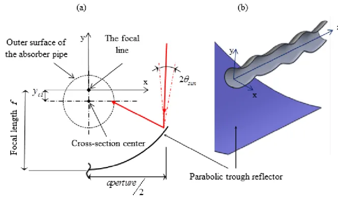
Figure 1.1 : Typical solar concentrator technologies [3]. ... 8 Figure 1.2: Representative cross-section of PTC. ... 14 Figure 2.1 : Main characteristics of the S-curved/Sinusoidal absorber. ... 39 Figure 2.2 : The sinusoidal receiver tube (a) Representative cross-section. (b) Set up of the novel
S-curved absorber. ... 40 Figure 2.3 : 3D schematic view of the novel vacuumed absorber. ... 40 Figure 2.4: Receiver tube heat transfer models... 46 Figure 2.5 : Contours plots of the heat flux density distribution q [ 2
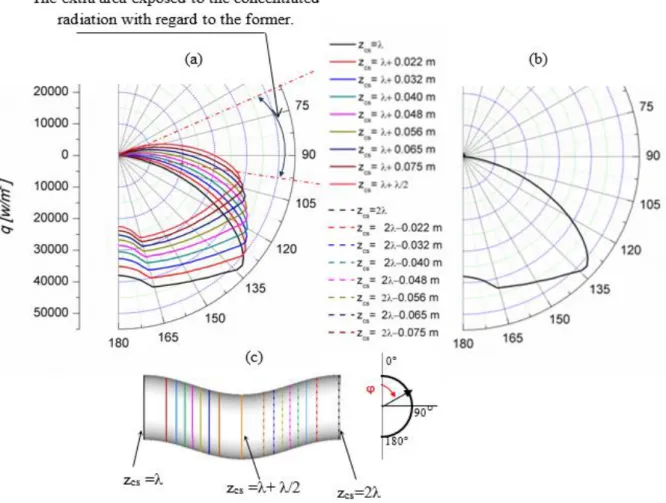
Wm ] on the outer surface of the absorber pipe, for qsun 933.7 Wm2. (a) The novel S-curved absorber. (b) The conventional straight absorber. ... 47 Figure 2.6 : Polar charts of q vs φ. (a) On a periodic segment of the novel S-curved pipe. (b) On the
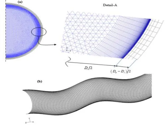
conventional straight absorber. (c) Cross-sections where the heat flux distributions (q) are extracted. ... 48 Figure 2.7 : North-South axis orientation of the trough. ... 50 Figure 3.1 : Typical meshing generated by GAMBIT 2.2.30. (a) The cross-section view and (b)
portion of the inner wall meshing. ... 57 Figure 3.2 : Validation of the simulation results for a laboratory scale sinusoidal pipe. ... 61 Figure 3.3 : Nu and f vs. the flow regime Reynolds number for
T
in
450
K
and2
933.7
sun
q Wm . ... 62 Figure 3.4 : Streamlines at xy-planes of various bends along the S-curved/sinusoidal pipe for
1 4
9.5 Re 12.3 10 in
m kgs and
T
in
450
K
. The pipe wall was omitted. ... 64Figure 3.5 : 2D-3D transition of vortices. (a) Tin500 K and min 3.5 kgs1, which corresponds to Re 82.7 10 3, (b) Re 112.3 10 3, (c) Re 175 10 3 and (d)
3
Re474.8 10 . Only the second periodic segment was shown
2 z 3
and the pipe wall was omitted. ... 65 Figure 3.6 : The sinusoidal nature of the curvature radius ... 66 Figure 3.7 : Plots highlighting the emergence of a new vortex at 22
z , Tin 450K . (a)
Re 64740, (b) Re 71210 and (c) Re 84160 which correspond, respectively, to the mass flow rates m5 k sg 1, m5.5 kgs1 and m6.5 kgs1. Coloured
zones represent the positive y-velocity contours. The pipe wall was omitted. ... 67 Figure 3.8 : The normalised velocity magnitudes V* and the bulk temperatures along the
absorber, for various mass flow rates at
T
in
450
K
, which correspond respectivelyto Re 65000, Re 85000 and Re 97000. ... 68 Figure 3.9 : Changes in the Nusselt number and the Friction factor for different HTF inlet
xii
Figure 3.10 : The contour plots of the pipe-wall temperature for two inlet temperatures (450K and 600K) and various mass flow rates. ... 71 Figure 3.11 : The circumferential temperature gradient and the mean heat transfer rate per meter
against Reynolds number ... 72 Figure 3.12 : Polar charts of the local Nusselt number at uppermost (solid lines) and bottommost
(dashed lines) bends. ... 74 Figure 3.13 : Streamlines at various locations along a segment of the S-curved pipe,
4
2 z 2
. ... 75
Figure 3.14 : Contours on the novel absorber for Tin 450 K and 1
5
in k
m gs (a) HTF
velocity contours on bends xy-plane, (b) Temperature contours of the pipe inner-wall and (c) HTF temperature contours at bends xy-plane. ... 76 Figure 3.15 : Curved shape of the generatrices at various azimuthal angles
. ... 77 Figure 3.16 : Change of the local Nusselt number along generatrix at various azimuthal angles.Colours correspond to those adopted in Figure 3.17 for the curved generatrices. ... 78 Figure 3.17 : The heat flux distribution against the azimuthal angle of the first half of a periodic
segment. ... 78 Figure 3.18 : The normalised mean Nusselt number Nu Nualong the pipe
z 4
for450
in
T K and for various mass flow rates, which correspond to Re 64736,
Re 71210, Re 84160 and Re 97100. ... 79 Figure 4.1 : The reduction of the solar absorber size. ... 88 Figure 4.2 : The similitude of the pressure drops through absorbers and the effect of the size
reduction on the S-curved absorber... 90 Figure 4.3 : The mean heat transfer enhancement, the pressure-drop penalty and the PEC of PTC
xiii
List of tables
Table 1. 1 : Solar energy collectors [1]. ... 6
Table 2. 1 : Geometric characteristics of the proposed S-curved/Serpentine absorber. ... 41
Table 2. 2 : Optical proprieties [1, 15, 16]. ... 41
Table 3. 1 : HTF properties [1, 5]……….58
Table 3. 2 : Critical Reynolds number………..59
Configurations study of PTCs Field for Optimizing HTFs Outlet Temperature 1
General introduction
In modern life, the sun’s rays energy can be converted and used as different thermal applications including water heating, space heating and cooling, industrial process heat and power systems.
Different technologies have been involved to serve the thermal applications, classified as concentrating and non-concentrating systems. Concentrating systems (including PTC, linear Fresnel, central receiver and parabolic dish technologies) designed mainly to produce steam; the steam is used to drive a turbine coupled with an electricity generator to produce electricity. The PTC plant is the most used concentrating technology system to convert Sun’s rays to thermo-dynamic energy to produce electricity.
The PTC plant efficiency can be affected by intrinsic (controllable) parameters including the optical efficiency of the PTC, heat transfer fluid thermo-physical properties…etc. Moreover, environmental and geographical parameters.
The PTC consists of parabola (mirrors), receiver tube, thermal fluid, structure and tracking system. Although the alignment of the receiver, the parabola optical parameters, rim angle and tracking system accuracy have been studied thoroughly; in the last two decades, numerical and experimental works on the HCE have been intensified. Introducing inserts inside the receiver tube with different configurations, proposing novel selective coating material as well as developing Mont Carlo Ray-Trace (MCRT) method for better understanding the optical model are studied.
Introducing inserts inside the receiver tube enhanced the heat transfer rate mainly by improving the mixing of the heat transfer fluid with the price of increasing pressure drop considerably. However, the thermal efficiency of a receiver with inserts relatively improved compared to CSST receiver.
Recently as discussed in chapter 1, a novel configuration proposed by Demagh et al.
2015 [61] to be used as HCE in the PTC system; the proposed tube configuration has an
Configurations study of PTCs Field for Optimizing HTFs Outlet Temperature 2 shows that no study has been conducted on thermo-hydraulic behavior of an S-curved tube as a heat collector element of the PTC unit.
Objectives of this thesis
Considering the actual state-of-the-art in modelling parabolic trough solar collectors, a receiver tube with inserts is characterized by excessive pressure drop and present relatively some challenges to manufacture compared to CSST receiver. The S-curved tube may be an alternative to improve heat transfer rate by the induced secondary flow due to waviness shape and less pressure drop favorized by keeping the inside diameter smooth (no inserts).
This thesis aims at:
Using user define function (UDF) to manifest the heat flux distribution on the outer surface of the novel S-curved tube and compare it with heat flux distribution on the outer surface of the CSST.
Studying the fluid flow and heat transfer in the novel parabolic trough collector to quantify pressure drop and heat transfer enhancement.
Finding a similitude relation between the novel S-curved receiver tube and the CSST receiver in terms of efficiency and size.
Replacing the CSST HCE of the typical SEGS LS2 plant by the novel S-curved tube and studying its new configuration in order to optimizing the heat transfer fluid outlet temperature and reducing its size.
Research approach
Several research works have been conducted to study the heat transfer and fluid flow in curved pipes as a practical engineering application. Potential applications of curved geometries in industrial processes include helical coil, bend tube, serpentine tube, spiral, and twisted tubes. However, limited studies have investigated turbulent flow in longitudinally curved pipes. As cited in chapter 2, Abou-Arab et al. 1991 [10] and Yang et al. 2002 [11] proposed correlations for friction factor of water flowing through a sinusoidal circular pipe.
Configurations study of PTCs Field for Optimizing HTFs Outlet Temperature 3 Through literature the SST k–ω turbulent model is suited for turbulent flow where high secondary flow involved, the model helps to catch fluid detachment near the wall and predicts well Dean vortices. Similar configuration to that studied by Abou-Arab et al. 1991 [10] is used in present study for validation purpose, the computational domain is generated and meshed by Gambit 2.2.30 by sweeping the meshed cross-section of the tube using quadrilateral elements with a structured mesh into the absorber pipe wall and an unstructured (Quad/Tri) non-uniform grids within it to insure y1 condition. The transport equations solved by Fluent 6.3 using coupled method, differentiated equations solved by second order scheme and the SIMPLE algorithm is performed for solving the pressure-velocity linked equation.
Research approaches adopted in this study can be summarised in the following points:
Validate the numerical model using correlations of Abou-Arab et al. 1991 [10] and Yang et al. 2002 [11] for laboratory scale S-curved tube.
After validating the model, the same model is used to simulate the novel PTC S-curved tube.
The heat flux on the outer surface of the tube calculated by UDF. The vacuumed annulus between glass and absorber considers only radiative heat flux, the glass was omitted in this study but its properties were taken into account in the optical model.
Obtained results from CFD had been processed and treated by Excel to be presented as graphs using Origin. Therefore, the streamlines of vortices presented using Tecplot.
Thesis layout
General introduction comprises the aims, the research approach and the layout of this project.
Chapter one presents a literature review of thermal applications of solar energy, solar power plant technology, proposed receiver tubes configuration and development made in terms of selective material coating as well as developed experimental, numerical and optical models analyzing thermo-dynamic phenomena through PTC HCE.
Configurations study of PTCs Field for Optimizing HTFs Outlet Temperature 4 Chapter two presents brief review on curved tubes applications, studied domain identification, numerical and optical models as well as involved mathematical equations. Chapter three presents models validation and obtained results. In addition to their analysis and discussions.
Chapter four presents similitude relation in terms of thermal efficiency between S-curved tube with reduced size and CSST with full size.
General conclusion presents the different conclusions from this work and recommendations for continuing it on the future.
Configurations study of PTCs Field for Optimizing HTFs Outlet Temperature 5
Chapter 1:Literature Review
Introduction
In this chapter, the main existing solar energy collectors for thermal applications including water heating, space heating and cooling, industrial process heat and power systems are presented. Furthermore, the power systems known by solar concentrating technology involving linear Fresnel collector, solar tower, parabolic dishes and parabolic trough are particularly discussed.
Through the brief review on existing and planned concentrating solar power (CSP) plants presented hereafter, the parabolic trough plants are the most used and sited well to be used thoroughly in the future. The parabolic trough collector considered as the backbone of the parabolic trough plant. The main elements of the parabolic trough plant are highlighted especially those forming the parabolic trough collector unit (receiver tube, structure and mirrors and thermal fluid) and thermal storage facility even if it is in some cases optional.
The parabolic trough collector have been investigated thoroughly experimentally and numerically aiming to improve its thermal and optical performances. The heat transfer fluid and parabola have had the same attention as much as the receiver tube. Nevertheless, this chapter reviews basically, subjects related to the receiver tube, involving heat transfer enhancement efforts by introducing inserts, selective coating evolution and introducing the fascinating MCRT method.
As mentioned in the general introduction, the main objective of the thesis is the investigation of the thermo-dynamic behavior of the newly designed S-curved tube, thus an exhaustive review on the existing works dealing with the receiver tube including involved modelling techniques and development through the history are discussed.
1.1. Solar energy collectors
The solar radiation energy is transformed through collectors to an internal energy carried out by the HTF. The energy of HTF can be then used directly as hot water or for other applications. Solar collectors can be classified as non-concentrating (stationary) or
Configurations study of PTCs Field for Optimizing HTFs Outlet Temperature 6 concentrating (Kalogirou 2004 [1]). The main difference is, the stationary collectors have the same area for intercepting and for absorbing solar radiation, whereas the concentrating collectors have much higher concentration ratio up to 1500, which is basically the ratio of intercepting area to receiving area. Solar collectors available in the market are summarized in the table 1.1.
Table 1. 1 : Solar energy collectors [1].
Motion Collector type Absorber
type
Concentration ratio
Indicative
temperature ratio (°C)
Stationary Flat plate collector (FPC) Evacuated tube collector (ETC) Compound parabolic collector (CPC)
Flat Flat Tubular 1 1 1-5 30-80 50-200 60-240 Single-axis tracking
Linear Fresnel collector (LFC) Parabolic trough collector (PTC) Cylindrical trough collector (CTC)
Tubular Tubular Tubular 10-40 15-45 10-50 60-250 60-300 60-300 Two-axes tracking
Parabolic dish reflector (PDR) Heliostat field collector (HFC)
Point Point 100-1000 100-1500 100-500 150-2000
1.2. Applications of solar energy
As can be seen from (Kalogirou 2004 [1]; Jebasingh and Joselin 2016 [2]), solar energy has wide range of applications and it offers many commodities for modern life. Typical applications of the various type of collectors include [1]:
Solar water heating, which comprise thermosyphon, integrated collector storage, direct and indirect systems and air systems.
Space heating and cooling, which comprise, space heating and service hot water, air and water systems, heat pumps and refrigeration.
Industrial process heat, which comprise air and water Systems, steam generation systems and desalination.
Configurations study of PTCs Field for Optimizing HTFs Outlet Temperature 7
Thermal power systems, which comprise the parabolic trough, power tower and dish systems, solar furnaces, and chemistry applications.
1.3. Solar concentrating technology
Solar concentrating systems can be classified according to the shape of their principal components especially reflectors thus the way they focus the sun’ rays and ultimately the whole process involved from extracting energy to its conversion to electricity or other forms. Therefore, solar concentrating technology can be subdivided into four categories as shown in the figure 1.1.
1.3.1. Parabolic troughs
The parabolic trough composed of a reflector with trough shape and a solar receiver. The reflector designed to reflect up to 90% of the intercepted sun’ rays, the absorber tube with selective coating is designed to absorb maximum of radiation and limit its emitting infrared radiation. Both reflector and receiver move in tandem in single axis tracking following the sun’ path form its raise to its set. Parabolic trough in most cases uses synthetic oil as heat transfer fluid. Most current concentrating solar power (CSP) plants are parabolic troughs [3].
1.3.2. Linear Fresnel reflectors
Linear Fresnel reflector has flat or slightly curved shape and fixed receiver tube placed at the center of the system. New design known as compact linear Fresnel reflectors can use two receiver tubes for each row of mirrors, thus producing the same amount of energy with reduced plant size and less cost. The linear Fresnel reflectors have less investment cost; generate direct steam easier than PTC, so exchangers and heat transfer fluids might be avoided. However, it is less efficient for electricity production and difficult to incorporate storage capacity [3].
1.3.3. Solar towers
A central receiver fixed on the top of tower, receives the sun’ rays, reflected by small reflectors called heliostats thus heating the heat transfer fluid. The solar tower can reach very
Configurations study of PTCs Field for Optimizing HTFs Outlet Temperature 8 high temperature and producing electricity more efficiently. The concept of solar towers is more flexible than previous systems [3].
1.3.4. Parabolic dishes
The sun’ rays concentrated by the reflector onto focal point supported above the center of dish. Parabolic dishes are considered as the highest in terms of solar to electric conversion performance of any concentrating solar power systems. Compact size, no need for cooling water, parabolic dishes are well placed to compute with any solar energy system. Hundreds or thousands of parabolic dishes have to be installed to build a large-scale plant in terms of energy equivalent to other typical concentrating solar power [3].
Configurations study of PTCs Field for Optimizing HTFs Outlet Temperature 9
1.4. Concentrating solar power (CSP) plants review
The first practical concentrating solar power (CSP) plant is a parabolic trough plant for powering an irrigation system, which was successfully completed by Frank Shuman in Meadi, Egypt, in 1913. It is waited until 1965, to build the first solar power plant in Sant’Ilario in Italy. The well-known nine parabolic trough Solar Energy Generating Systems (SEGS), built between 1984 and 1990 in California, USA, remain the largest solar energy generating facility in the world today, with 354 MWe of installed capacity. In Seville, Spain, the first commercial solar tower PS10 in the country with a capacity of 11 MWe, was accomplished in 2007 (Isabel et al.
2011 [4]).
Hank Price et al. 2002 [5] presented barriers on the way of developing concentrating
solar power, they described also the efforts made for building the fantastic SEGS plants. The description of new technologies in developing and improving reflectors, receivers and power cycle have been presented thoroughly.
Until 2011, 96.3% of operational concentrating solar power are parabolic trough technology with up to 29 plants in operation and around 1220 MWe of installed power in the
world (Isabel et al. 2011 [4]).
A review on CSP plants, the world irradiation distribution and its estimation, comparison between different CSP technology and some development in the field of CSP are presented by
Zhang et al. 2013 [6]. As during the absence of sun’ irradiation, a backup system is required
to ensure the continuity of delivering power to customers, the feasibility of hybridization with renewable or conventional energy has been highlighted by Pramanik et Ravikrishna 2017 [7] Based on the paper of Tomislav et al. 2012 [8], there are about 47 parabolic trough power plant around the world with 33 in Spain, 7 in USA and 2 in Iran. Italy, Morocco, India, Egypt and Algeria has one plant for each.
Pelay el al. (2017) [9] have divided CSP plants into five groups 19 plants in operation
with production began before year 2000, 24 plants in operation with production started between year 2000 and 2010, 85 plants in operation with production began after 2010, 35 plants now under construction, and 74 planned plants. The total number of these samples
Configurations study of PTCs Field for Optimizing HTFs Outlet Temperature 10 reaches 237 CSP plants. They include commercial, demonstration, research and development plants.
From the historical evolution of used CSP technologies, parabolic trough collector (PTC) and solar power tower (SPT) are the most used technologies for plants in operation. Meanwhile, trends also show that there will be a higher ratio of SPT for CSP plants in project. Linear Fresnel reflector (LFR) represents the third most frequently used CSP technology. Parabolic dish collector (PDC) is a relatively young technology with no plants in activity. Nevertheless, it represents 7–9% of plants under construction and planned, making it a non-negligible technology in the future (Pelay el al. (2017) [9]).
A parabolic trough solar power plant is composed of solar field (PTC unit including solar receiver, parabola and structure with tracking system), thermal storage as if it is required and power block (turbine, generator, etc.). Only parts of the PTC unit are discussed in present work.
A parabolic trough collector consists of a highly reflective parabolic mirror with a solar receiver positioned at the focal line of the parabolic. The heat transfer fluid (thermal fluid) is heated by the solar energy reflected and concentrated by mirror onto the receiver tube. During high insolation, solar energy can be stored to be used during low or no insolation for steadier electricity production. The metal support structure is used to support the weight of the parabolic and the tracking mechanism as well as the wind loads.
1.4.1. Solar Receiver
The solar receiver or heat collection element (HCE) is one of the main functional units of a solar PTC. Many techniques were attempted to enhance the heat transfer potential in the tube receiver. Which, includes techniques such as half insulation receiver, cavity receivers, vacuum outer shell, inclusion of inserts (turbulators), baffles, artificially roughened sinks, selective coatings. The outer surface of the receiver tube is basically coated to improve its solar radiation absorbance and to limit its thermal radiation emittance. The receiver tube also placed inside evacuated glass envelope to reduce both convective and radiative heat loss from the tube receiver. The solar receiver is considered as a key element in the parabolic trough system, it should loss less thermal energy principally by radiation and increasing its heat
Configurations study of PTCs Field for Optimizing HTFs Outlet Temperature 11 transfer to the thermal fluid. The heat transfer to the thermal fluid can be enhanced by using inserts; which improve the turbulence, creating secondary flow as well as increasing the effective heat transfer area. The inserts can be twisted tapes, coil inserts, dimples, baffles, metal foam, porous discs and corrugated tube etc. A selective coating is very important to increase the absorbance and minimize thermal radiation loss especially for relatively high working temperature, Mo-Al2O3, Mo–Si3N4, Molybdenum and Silica nitride, matt black
painting, black chrome and black nickel-chrome coating can operate up to 600 °C and reaching an absorbance of 98% (Hafez et al. 2018 [10], Kumaresan et al. 2017 [11]).
1.4.2. Structure and mirrors
The collector structure must be robust enough to overcome different loads, the structure should be lighter for cost optimization, and challenges of manufacturing have to be carefully estimated. A number of structural concepts have been proposed such as steel framework structures with central torque tubes or double V-trusses, or fibreglass in order to achieve the cost-effectiveness balance (Kalogirou et al. 1994 [12], Adrian et Randy 2009 [13]).
The mirrors fixed with a rapid hardening adhesive on the steel structure support, which has an exact parabola shape; finally, the solar collector element is installed on supporting pylons. The installation and mounting of the support structure has high influence on the total plant performance. The support structure has to meet the following structural requirements (Schweitzer et al. 2014 [14]):
The structure must be robust and rigid to hold the initial form of the parabola by avoiding deformations that would be caused by environmental conditions as well as temperature differences.
Lightness is an effective parameter to reduce cost and improve flexibility of the facilities.
The most commonly reflectors in commercial solar thermal electricity are silvered-glass reflectors, the glass is a very stable material physically and chemically, the main challenge is its fragility especially thin layer, which needed back protection. The poor optical performance of the aluminum can be improved by coated and methacrylate aluminum film, which can be used as future alternative to conventional glass reflectors. A knew under development
Configurations study of PTCs Field for Optimizing HTFs Outlet Temperature 12 reflectors based on silvered-polymer seem to be promising, they are more flexible, cheaper and lighter. They have better optical reflectance then methacrylate aluminum film reflectors. Therefore, silvered-glass reflectors have not yet been displaced, because it has the highest reflectance and long optical durability (García et al. 2016 [15], Blanco et Santigosa 2017 [16]).
1.4.3. Thermal fluid
The HTF type is imposed by the solar receiver and the thermodynamic cycle of the plant. In the meantime the HTF properties, define the type of the solar receiver to use, from recent studies, the tube geometry is the most common receiver. High thermal conductivity improves heat transfer, so introducing inserts to improve heat transfer could be avoided. Low viscosity can reduces pressure drop, so low working pressure permits the use of thin wall, thus reducing wall temperature gradient and mechanical stress, as a result long lifetime of the receiver tube and less cost. A large specific heat capacity can be an advantage for direct thermal storage. Current thermal fluids used in CSP plants: thermal oil, molten salt and water-steam can achieve thermodynamic efficiency from 35 to 42%. New molten salt, liquid metals, pressurized gases, supercritical fluids, particle suspensions are new HTFs, which are considered stable at 700 °C and more. Using knew HTFs can achieve a thermodynamic efficiency up to 50% and more (Benoit et al. 2016 [17]).
1.4.4. Thermal storage
The main disadvantage of solar energy is its intermittently. The stored thermal energy during sunshine periods, can be used during insufficient irradiation to reduce the dependence to conventional energy hybridization by burning fossil fuel. About 47% of the solar plants in operation integrate thermal energy storage (TES) system. There are currently three kinds of TES systems available: sensible Heat storage, latent heat storage and thermo-chemical heat storage. The type of TES system to be used, depends mainly on the cost of investment and the fluid to be stored (Pelay el al. (2017) [9]).
Sensible heat storage: is currently the most commonly used technology with their limited energy density; it exists in solid form (sand, rock, mineral oil, cast iron etc.). most studied material are solid such as concrete, castable ceramics, new concrete with polypropylene fibers, and other material such as graphite; liquid such as molten salt,
Configurations study of PTCs Field for Optimizing HTFs Outlet Temperature 13 solar salt, Hitec, salt with nanoparticles and other liquid like oils, liquid sodium; and gaseous materials like compressed air or steam.
Latent heat storage: it is based on phase change material (PCM), it could be solid-liquid or solid-solid, it is known with its higher energy density but low thermal conductivity thus long charge and discharge processes. The conductivity may enhanced by some additives to PCM, like metal alloys, graphite, insertion of a metal matrix or foam as well as special design of TES system with embedded heat pipes or finned heat pipes. Inorganic and organic substances can be also used for high temperature range of 100-900°C.
Thermochemical heat storage: it is based on reversible chemical reactions by endothermic chemical reactions and stored in chemical potential. Then stored heat recovered by the reversed exothermic reaction, sometimes by adding a catalyst. It is 10 times greater than latent storage. Metallic hydrides, carbonates system, hydroxides system, redox system, ammonia system and organic system can be used for thermo-chemical heat storage at medium or high temperatures (300–1000°C). These common materials used in thermochemical storage have low thermal conductivity, which could be improved by expended graphite matrix, aluminum foam and by adding nanoparticles like SiO2 to improve the problem of thermal stability of thermochemical
materials.
1.5. State of the art of the solar receiver as part of the PTC
During the Roman invasion against Greek in the third century B.C, there are rumors that Archimedes had used the soldiers shields or mirrors to concentrate sun’ rays onto the Roman fleets, the high temperature resulted from the concentration of sun’ rays, turned the Roman fleets into ashes. Many writers have dismissed these rumors. After a Greek and Roman period, Europe entered a Dark Ages. Whereas, science flourished in the North Africa where the first contributions to the theory of optics in 800 years were developed by Abu Ali Hasan al-Haitham (born in 965); He correctly argued that vision results from light entering the eye, not the reverse. He tackled practical problems like the origin of rainbows, binocular vision, the apparent increase in size of planets near the Earth’s horizon, reflection, refraction, focusing with lenses, and the properties of spherical and parabolic mirrors [18].
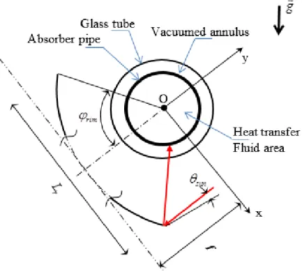
Configurations study of PTCs Field for Optimizing HTFs Outlet Temperature 14 The main elements of parabolic trough collector and their characterization parameters are presented in figure 1.2.
Figure 1.2: Representative cross-section of PTC.
The use of concentrating collectors for furnaces purpose date back to 1774 when the French chemist Lavoisier constructed powerful lenses to concentrate solar radiation, the furnace reached a temperature of 1750 °C using 1.32 m lens plus secondary 0.2 m lens, this temperature was the maximum achieved temperature for a century. In 1875, Mouchot made truncated cone reflector, consisted of silver-plated metal plates with diameter of 5.4 m and collecting area of 18.6 m2, its moving part weighed 1400 Kg (Frank 2003 [18], Kalogirou 2009
[19]).
Abel Pifre, made a solar engine based on parabolic reflectors, which are made of small mirrors and they shaped like Mouchot’ truncated cones. Steam engines operated using steam generated by concentrating solar radiation, for different applications such as driving printing machine by Mouchot 1878-1880 and powering water pumping by Eneas in 1901 using 10 m diameter focusing collector. John Ericsson, an American engineer, developed the first steam engine using solar energy systems of eight parabolic troughs, the systems used either water or air as heat transfer fluid. After, In 1912 Frank Shuman with C.V. Boys built a largest pumping
Configurations study of PTCs Field for Optimizing HTFs Outlet Temperature 15 plant parabolic cylinder to focus sunlight onto a long absorbing tube, each cylinder was 62 m, the total area of used cylinders was 1200 m2. The solar engine had an output of 37 to 45 KW
continuously for a period of five hours ([18], [19]).
The onset of World War I and II, cheaper fuel and high cost of investment in solar energy caused loss of interest in its development. Interest in solar concentrator began to rise again in the 1960s [19].
The effect of distance from the focal plane on the uniform flux had been revealed by
Robert et al. 1957 [20], the area of uniform flux decreases as the plane of interest moves away
from the focal line, then it increases in size and uniformity at a distance of over two sun images from the focal plane. The plane of interest should be positioned within a distance of one-half of a sun image unit from the focal plane in order to get maximum delivered flux. For studied range of rim angles between 30° to 60°, the heat flux increases as the rim angle increases as well as for the flux distribution.
In 1961, Cobble [21], presented a theoretical concentration as a function of relative
aperture (mirror aperture to focal length), he developed the optimum concentration for plate, circular cylindrical and parabolic cylinder mirror targets, he considered a parabolic cylinder mirror target with a relative aperture of 4 as an ideal target shape.
Lof et al. 1962 [22], studied experimentally and theoretically a parabolic cylindrical
reflector with aluminum sheet of 12 feet length, 6.19 feet aperture, focal length 1 foot, rim angle 114°, the reflector assembly inclined at 40° with the horizontal, with a tracking system. The receiver made of standard wrought iron pipe, which were coated with a flat black paint with an absorptivity of 0.95 for diameter receivers from 1.9 to 2.375 in, except for diameter of 1.05 in where the absorptivity was 0.93. The average reflectivity of aluminized Mylar reflector surface was 0.76 at average incident angle of 20 deg. The smaller tube failed to intercept a larger portion of the radiation and resulted in 31 % loss in shape factor, in terms of heat losses, beyond operating temperature of 350 F small tube had lower loss. Reflector misalignment results in shifting and enlargement of the focal zone and consequent shape factor discrepancies, particularly with the smallest receiver. Theoretical and experimental
Configurations study of PTCs Field for Optimizing HTFs Outlet Temperature 16 curves of efficiency, average intensity as well as maximum focal zone flux go through a maximum at an optimum receiver radius.
The elliptic cylinder attains a higher concentration than both the parabolic and the circular pipe targets. The optimum target geometry could reach a slightly higher absolute value for maximum concentration than other target geometries (Lumsdaine and Cherng 1976
[23]).
Experimental and theoretical comparative study was performed by Singh and Cheema
1976 [24],They constructed and studied cylindrical reflector of parabolic cross section and
a circular absorber with length 244 cm, focal length 7.62 cm and relative focal length (
f
/ L
r ) of 0.1. The reflecting surface was of buffed aluminum. The receiver assembly consisted of a copper tube coated with a thin layer of nickel oxide and enclosed in the concentric glass tube. The authors showed the performance and optimal parameters of cylindrical parabola collector. Ideal theoretical concentration ratios for flat, circular, and the parabolic cylinder mirror of Cobble [21] had been modified by introducing insulating factor instead of considering the surface, which does not receive the reflected sunrays as perfectly insulated. The use of aperture as a characteristic length has many advantages over the use a focal length as characteristic dimension. The performance of the absorber can be defined as a ratio of the absorber temperature to the stagnation temperature. Absorptivity to emissivity ratio and the stagnation temperature can be used as a rough guide for the selection of a coating. Finally, the performance of the collector was well predicted.Ramsey et al. 1977 [25] studied experimentally a cylindrical parabolic trough
concentrator which, is 1.2 m wide and 4.2 m long with focal line of 19.4 cm. Alzak, anodized aluminum reflector sheeting, used as reflector of the parabola with measured reflectance of 0.81. The absorber tube has an outer diameter (OD) of 2.54 cm, surrounded by a glass of 10 cm inner diameter (ID) under vacuumed annulus and the water was used as HTF. A heat pipe working at low temperature around 40 °C and two absorbers of stainless steel working at temperature of 300 °C, were used: A heat pipe painted with 3M Black Velvet with absorptance of 0.95. An absorber electroplated with bright nickel covered by Al203-MoOx -AI203 (AMA)
Configurations study of PTCs Field for Optimizing HTFs Outlet Temperature 17 coated with a nonselective black paint with absorptance and emittance of 0.96. The authors observed a little effect of tracking error within ±0.5 deg on the performance, beyond that the effect becomes more severe. As the operating temperature increases, the performance decreases and the heat loss increases too. The thermal loss of selective coated absorber operating at 300 °C is lower than that for the non-selective case. In the case of selectively coated absorber, the maximum efficiency obtained around solar noon is approximately 50 percent, whereas it is around 22% in the case of non-selectively coated absorber.
In the 1980s, most studies were concentrated on compound parabolic concentrator (CPC) to enhance the amount of sun’ rays, which could be reflected by mirror and eventually concentrated onto the receiver tube. A comparison have been made between simple parabolic concentrator (SPC) and CPC in terms of materials use, acceptance angle and concentration ratio. SPC has an advantage in reduced materials used over CPC, but CPC has higher acceptance angle by three times. The SPC can collect most non-direct radiation with concentration ratio less than 10 (by enlarging the absorber tube to intercept defocused radiation) (Grimmer 1979 [26]). Newly designed reflector (CPC) by Mcintire 1980 [27] to eliminating gap losses between the tubular absorber and the reflector and enhancing the absorptance of the receiver.
The mirror-receiver tube intercept factor, absorptivity-transmissivity product of the receiver tube and cover tube, the end loss factor and receiver tube misalignment, an absorber with low emissivity coatings, glass-tube annulus evacuation and anti-reflection coating. These factors and other influence the performance of the PTC, therefore they should be identified for the design of the PTC (Clark 1982 [28]).
A ray-tracing technique comparison between CPC and PTC demonstrated that CPC has superior optical behavior regarding the acceptance angle and the exploitable part of the diffuse insolation (Prapa et al. 1987 [29]). A superior performance can be achieved with CPC incorporating inverted-Vee absorber fin rather than conventional cusp-reflector CPC design
(Norton et al. 1989 [30]).
Grald et al. 1989 [31] studied by one-dimensional finite-difference FORTRAN 77
Configurations study of PTCs Field for Optimizing HTFs Outlet Temperature 18 material properties on the thermal efficiency. Studied tube is composed of an envelope, fluid inlet channel, porous absorber and an insulation. The porous absorber consists of several layers of etched stainless steel screen with 50 meshes per inch (20 per cm). The screen has a porosity of approximately 0.4 and is 0.12 inch (3 mm) thick.
A unified model for optics and heat transfer in line-axis concentrating solar collector were used to simulate heat transfer around the receiver tube of CPC. The combination of two-dimensional steady state finite element analysis of convective heat transfer and ray-trace techniques highlighted the effect of acceptance angle, inclination, focal line and other parameters on heat transfer of the CPC (Eames et al. 1993 [32]).
Dudley et al. 1994 [33] studied thermal efficiency and thermal losses of three receiver
configurations with vacuumed annulus, air in the annulus and bare tube, two types of coating applied to the steel receiver tube were used cermet selective and black chrome coating. Tested module is similar to the smallest portion of complete SCA LS2 PTC used in Solar Thermal Electric Generation Systems (SEGS) with 7.5 m length and an aperture of 5 m. The LS2 presents 65% of three generations of installed collectors at the nine SEGS plants. The on-sun test performed at Sandia National Laboratories (SNL) showed that efficiency of cermet coating is better than that of black chrome. The heat loss of bare tube and air in the annulus is greater than that of vacuumed annulus, the heat loss increases considerably as fluid temperature increases.
Odeh et al. 1998 [34] studied the performance of a parabolic trough collector LS2 from
SEGS plant to develop a model of thermal loss of the collector basing on correlation function. Their model showed that the thermal loss of vacuumed insulted absorber is less than that of lost vacuum and bare tube showed higher thermal loss. The authors studied the heat transfer variation with respect to the water phase (single-phase water, mixture of liquid water and steam, dry steam). The effect of the absorber temperature and the inlet temperature on heat loss had also been conducted. The heat loss when using synthetic oil as heat transfer fluid was found to be greater than when using water. The thermal stress severity might be controlled by adjusting feed water flow rate with radiation level thus; constant temperature two-phase region should cover most of the absorber tube.
Configurations study of PTCs Field for Optimizing HTFs Outlet Temperature 19 The EUROTROUGH - Parabolic Trough Collector would permit the reduction of solar field cost by 14% due to the weight reduction and could be integrated in the successful SEGS plants of California. The weight of EUROTROUGH is about 14% lesser than the weight of LS-3 collector. The structural deformation of the new design is considerably less than LS-3. Therefore, the sealing against leakage during operation has been improved. The thermal annual output improved up to 20% thanks to improved absorptivity and emissivity, the applied Universal Vacuum Collector (UVAC) selective coating is designed to work at vacuum and exposed outdoor conditions, with no oxidation or oxide deposit on the glass tubes at temperature up to 400 °C. The glass to metal connection zone and the bellow connections are shielded in the way of maintaining fixed relative position in spite of the dilation of the tube during heat up (Geyer et al. 2002 [35]).
Cylindrical parabolic trough concentrator simulation was run by Singh and Sulaiman
2003 [36], the simulation run for three different working fluid, the concentration ratio
increased until a maximum theoretical value of 212, the efficiency increased until the concentration ratio reached 10 then gradually decreased by at least 53%. The balance should be achieved, the increasing in the aperture area, increases the heat loss but in the meantime decreases the optical loss.
Brooks et al. 2005 [37] constructed a parabolic trough collector, characterized by a collector of 5 m long, aperture width of 1.5 m and rim angle of 82.2°. The surface consists of stainless steel sheets covered with SA-85 film. An absorber tube of diameter 28.6 mm giving a concentration ratio of 16.7, the absorber was coated with selective coating, a glass tubing with transmittance of 0.92 and refractive index of 1.473. The annulus was sealed using temperature-resistant O-rings allowing for expansion of the inner absorber. A single vent enabled evacuation of the annulus using a vacuum pump. The water is used as heat transfer fluid at turbulence regime. The maximum temperature in this study was limited at 80 °C due to limitations in the fluid circulation system. At lower temperatures, heat loss is low and the glass adversely affects performance by reducing optical efficiency. At higher temperatures, performance is dominated by heat loss, which is prevented more effectively by the shielded receiver.
Configurations study of PTCs Field for Optimizing HTFs Outlet Temperature 20
Arasu and Sornakumar 2006 [38], studied the performance of a new parabolic trough
collector hot water generation system with a well-mixed hot water storage tank, the parabola with a rim angle of 90°, constructed of fiberglass, the solar reflector material is SOLARFLEX foil with reflectance of 0.974. The copper tube coated with a heat resistant black paint used as receiver tube of 1.25 m length positioned at a focal length of 0.2 m, the annular gap around the receiver ensured by a glass envelope and rubber cork seals at both ends. Temperature, solar beam radiation intensity, mass flow rate and the wind speed were measured by resistance temperature device (RTD) sensors, pyrheliometer, rotameter and vane type anemometer respectively. The efficiency depends on incident beam radiation and the useful heat gain, the storage tank temperature raised from an initial temperature of 35°C to a maximum temperature of 73.84°C as no energy withdrawn from the storage tank during the collection period of 7 hours counting from 9 A.m on April 30, 2005 in India.
Krüger et al. 2008 [39], studied experimentally Solitem PTC1800 for medium working
temperature 150 to 190°C to produce steam as driving medium for the absorption chillers. The mirror shape characterized by absorber reflection method (ARM), they found according to ray tracing calculations an interception factor of 83%, the temperature, mass flow and direct normal irradiation (DNI) were measured by adequate sensors. The study revealed relatively low thermal loss and significant optical losses.
The most recent studies have concentrated on the receiver as a key element in PTC system. The heat transfer enhancement has consumed scientists theoretically and experimentally. Introducing inserts (turbulators) in receiver tubes have been studied thoroughly. The coating technique to improve optical properties of the receiver has been interesting subject. The practical technique to evaluate the heat flux around the receiver tube has been relatively achieved by MCRT.
Burkholder and Kutscher 2008 [40] performed an off-sun test of the Solel UVAC3, they
developed a correlation predicting heat loss from the absorber to the ambient based on the average temperatures difference of the receiver and the ambient; the correlation is valid for ambient temperature ranges from 13 °C to 33 °C. However, developing this heat loss correlation is not the only parameter to evaluate the receiver performance. Later, in 2009 the authors [41] studied Schott 2008 model year PTR70 receivers performed inside the laboratory
Configurations study of PTCs Field for Optimizing HTFs Outlet Temperature 21 under controlled conditions. The authors derived the emittance of the absorber from heat loss testing results and introduced it in the heat loss model correlation. Based on this correlation, improved selective coating of Schott 2008 PTR70 model improved electricity generation by 5% relative to previous PTR70s model.
1.5.1. Heat transfer enhancement in the receiver tube by introducing inserts
Reddy and Satyanarayana 2008 [42] developed 3D numerical model to evaluate the
performance of the receiver tube of the solar parabolic trough concentrator (SPTC) with different configurations of porous inserts of square, triangular, trapezoidal and circular shapes. The authors used k-ε RNG turbulent model with standard wall function approach using the CFD package FLUENT. The receiver tube with trapezoidal fin showed better performance. At a Therminol VP1 flow rate of 6.4 Kg/s, the heat transfer enhancement is about 13.8% with a pressure drop of 1.7 KPa.
The numerical study of thermal analysis of solar parabolic trough with porous disc receiver showed that the introduction of porous discs in the receiver improves the heat transfer but with a price of pressure drop. The top half-porous disc receiver with an inclination of 30° permitted higher enhancement in heat transfer with 64.2% and 457 Pa as pressure drop for Reynolds number of 31845 in comparison to conventional tubular receiver (Kumar and
Reddy 2009 [43], Mwesigye et al. 2015 [44]).
Muñoz and Abánades 2011 [45], [46] investigated numerically a possible improvement
in terms of thermal efficiency of the receiver tube by introducing helical internal fins. The authors presented that the overall performance enhancement by 2% is reachable. Lower helix angle is sufficient for enough mixing with lower pressure drop unlike high helix angle, which causes excessive pressure drop. The authors believed that the cost increase of the finned collector tube could be compensated by not using absorbing coating, the glass and the glass-tube vacuum system as well as maintenance cost reduction motivated by the reduction in tube mechanical fatigue caused mainly by large temperature differences in conventional tube. After, Huang et al. 2015 [47] studied in addition a receiver with dimples and protrusions, they found that the performance evaluation criteria (PEC) for tube with dimples is 1.23 to 1.37, which is greater than the PEC for tubes with protrusions and helical fins. Huang et al. 2016
![Table 1. 1 : Solar energy collectors [1].](https://thumb-eu.123doks.com/thumbv2/123doknet/2324529.30006/20.892.147.850.326.679/table-solar-energy-collectors.webp)
![Figure 1.1 : Typical solar concentrator technologies [3].](https://thumb-eu.123doks.com/thumbv2/123doknet/2324529.30006/22.892.236.734.497.973/figure-typical-solar-concentrator-technologies.webp)
![Table 2. 2 : Optical proprieties [1, 15, 16].](https://thumb-eu.123doks.com/thumbv2/123doknet/2324529.30006/55.892.148.761.229.604/table-optical-proprieties.webp)

![Table 3. 1 : HTF properties [1, 6]](https://thumb-eu.123doks.com/thumbv2/123doknet/2324529.30006/72.892.145.724.288.821/table-htf-properties.webp)
