Science Arts & Métiers (SAM)
is an open access repository that collects the work of Arts et Métiers Institute of
Technology researchers and makes it freely available over the web where possible.
This is an author-deposited version published in: https://sam.ensam.eu
Handle ID: .http://hdl.handle.net/10985/7993
To cite this version :
Corinne NOUVEAU, Brahim TLILI, Hamid AKNOUCHE, Yacine BENLATRECHE, Bhavesh
PATEL - Comparison of CrAlN layers obtained with one (CrAl) or two targets (Cr and Al) by
magnetron sputtering - Thin Solid Films - Vol. 520, n°7, p.2932-2937 - 2012
Any correspondence concerning this service should be sent to the repository
Administrator : archiveouverte@ensam.eu
Comparison of CrAlN layers obtained with one (CrAl) or two targets (Cr and Al) by
magnetron sputtering
C. Nouveau
a,⁎
, B. Tlili
b, H. Aknouche
c, Y. Benlatreche
d, B. Patel
aaLaboratoire Bourguignon des Matériaux et Procédés, LaBoMaP, Centre Arts et Métiers ParisTech, Rue Porte de Paris, F-71250, Cluny, France bUR. Mécanique Appliquée, Ingénierie et Industrialisation (M.A2I), ENIT, BP 37, Le Belvédère, 1002, Tunis, Tunisia
c
URMPE, F.S.I. Université M'Hamed Bougara, 35000, Boumerdes Algeria
d
Laboratoire de Mécanique de Lille, LML CNRS UMR 8107, Centre Arts et Métiers ParisTech, 8 Boulevard Louis XIV, F-59046, Lille cedex, France
a b s t r a c t
Keywords:
Chromium Aluminum Nitride Magnetron Sputtering sintered target Mechanical Properties Stress
Crystal Structure
The aim of this study is to compare the properties of CrAlN coatings obtained by magnetron sputtering with one (CrAl) or two targets (Cr and Al). The influence of parameters such as the target bias voltage, the working pressure, the deposition time and the bias voltage applied on the Cr or Al targets on the properties of the layers was studied. We characterized the films by X-ray Diffraction, Scanning Electron Microscopy, coupled with Energy Dispersive Spectroscopy, nanoindentation and their residual stresses were also determined. The optimal films obtained with both methods are well crystallized, well-adherent to the substrate, and con-tained similar amounts of Al (20–30 at.%). The optimal coatings synthesized with one target presented prop-erties not as good as those realized with two targets. Nevertheless, films made with one target showed a lower frictional coefficient probably due to composition control. The lack of compositional control with the use of one target limits the optimization process. With two targets, we have greater control over the film composition. This leads to higher hardness, lower stresses, and improved Young's modulus over films pro-duced with a single CrAl target. Additionally, the morphologies are different (columnar with CrAl and
dense with Cr and Al). To conclude, it seems more justified to work if possible with two independent targets. .
1. Introduction
Ternary systems, such as MeAlN (with Me = Ti, Cr etc.), are attracting more and more attention from the industry. This is due to their high resistance to wear. Several experiments have led to the de-velopment of TiAlN or CrAlN hard coatings by varying the aluminum target bias voltage to improve the properties of the traditional TiN and CrN. Titanium-based coatings, especially (Ti,Al)N, are industrial state-of-the-art tool coatings for most machining operations. Indeed, it is known that Al permits higher working temperatures because of the alumina thermal barrier that protects the tool core during high speed machining. In addition, other ternary systems such as CrSiN, TiSiN, CrWN or TiCN have been studied during the last decade, but we will focus our discussion on CrAlN. Due to the effectiveness of Al additions in the TiN binary system, the same result was expected in the CrN system. CrN is increasingly used in the industry and may replace TiN in certain applications due to its better corrosion resis-tance and lower friction coefficient. It appeared to be a logical step to develop the CrAlN ternary system to work at temperatures higher
than 700 °C (thermal stability of the binary CrN system). Neverthe-less, the topic of our work is not to compare TiAlN and CrAlN layers but to compare CrAlN layers obtained by magnetron sputtering with a sintered target (Cr75Al25) versus two elemental targets (Cr and Al). Actually, we found no literature dealing with such a study and it would be very interesting to compare the properties of the deposit-edfilms obtained according to the variable deposition conditions like working pressure, gas mixture, gasflow, bias voltage but also the kind and number of targets in the same deposition system. Since 2000, most of the experiments on CrAlN and TiAlN ternary systems have used a single sintered target[1–13]instead of two targets[14–19]. According to the deposition technique (one cathode or more available) and the applications involved, they employed targets with afixed com-position such as Cr90Al10[1], Cr50Al50[3], Cr30Al70[4], Cr75Al25[7]to de-posit CrAlN films, or Ti33Al67 [10,11] and Ti50Al50 [5,8,9,11,12,13]. Recently, Bobzin et al.[2]showed that the composition of coating sys-tems deposited by single component targets (e.g., titanium/chromium and aluminum) in a dual-cathode arrangement can easily be altered byfirst changing pulse sequence, e.g., TOn, TOffand second a change in DC (Direct Current) power rate, e.g., increase in pulse energy. The high mobility of ions and, in particular, electrons results from a high ionization of the pulsed plasma[20]. This gain in mobility canfinally lead to higher adatom mobility, resulting in different coating structures. The aim of the present study is to compare the physicochemical and
⁎ Corresponding author. Tel.: +33 385595335; fax: +33 385595370.
E-mail addresses:nouveau@cluny.ensam.fr(C. Nouveau),tlilii_brahim@yahoo.fr (B. Tlili),h.aknouche@yahoo.fr(H. Aknouche),benlatrechey@yahoo.fr(Y. Benlatreche), Bhavesh.PATEL-7@etudiants.ensam.eu(B. Patel).
mechanical properties of CrAlN layers obtained by dual RF (Radio Frequency) magnetron sputtering using one sintered Cr75Al25target or two targets (pure Cr and Al) to establish what kind of solution is the best to obtain good protective coatings for mechanical applications.
2. Experimental details
The deposition of CrAlN coatings was carried out by a dual RF magnetron sputtering system (NORDIKO type 3500–13.56 MHz) (Fig.1). First, CrAlN layers were obtained by using a sintered Cr75Al25 target. The deposition time wasfixed to 90 min. We studied the varia-tion of parameters such as the nitrogen content in the plasma (10, 17.5, 25, 35, 50 and 100%), the working pressure (0.2, 0.4, 0.8 and 1.2 Pa) and the target voltage (−300, −500, −700 and −900 V). For comparison, pure Cr (99.995%) and Al (99.999%) targets were used. To vary the Al content in the CrAlNfilms, we first fixed the Cr applied voltage at−900 V and varied the Al voltage (−300, −500, −700 and−900 V); second, we fixed the Al applied voltage at −900 V and varied the Cr voltage (−500 and −700 V). The working pressure was about 0.4 Pa, the plasma discharge contained 80% of Ar and 20% of N2 and the deposition time was 90 min. In both cases, the targets were 101.6 mm in diameter and 3 mm thick. The substrate/target distance was 80 mm.
To determine the physicochemical, mechanical and tribological properties of thefilms, we employed silicon (10×10 mm²) for inter-nal stress and thickness measurements, SiO2(10 × 10 mm²) for hard-ness and Young's modulus determination, and 90CrMoV8 steel samples (“La Forézienne-MFLS”, France trademark) frequently used to fabricate tools for wood machining [21](20 × 20 mm²) for pin-on-disk tests. Nanoindentation tests have been made with an NHT from CSM Instruments equipped of a Berkovich indenter. The test pa-rameters were a maximum load of 10 mN, a load and unload rate of 5 mN/min and we employed the sinus mode (1 Hz of frequency and 1 mN of amplitude). The tribological tests of pin-on-disk were made under an applied load of 5 N, with a 100Cr6 ball of 5 mm diameter, with an alternative friction for each 8 s and a test duration of 10 min. The steel samples were ground to a roughness Raof around 0.2μm and Rtof around 1μm yielding roughness similar to industrial tools. The morphology, thickness and the composition of the CrAlN coatings were determined by Scanning Electron Microscopy (SEM-5 kV) observations and Energy-Dispersive X-ray Spectroscopy (EDS) microanalyses (Jeol JSM-5900 LV). A calibration was realized on sili-con (light element). Then the calculations of the composition of layers were made thanks to the data we obtained from a specific calibration realized at 5 kV on pure metals or compounds. X-ray Diffraction (XRD) analyses (SIEMENS D500, Co-Kα radiation, Bragg-Brentano configuration) permitted the determination of the crystalline orienta-tions of the CrAlN layers. The residual stress was calculated using the Stoney's equation [22]after measuring the radius curvature of the silicon coated samples with the Newton's ring method[23]or by 2D profilometry (VEECO-DEKTAT 3030).
Before deposition, all the substrates were ultrasonically cleaned in ethanol. The targets and the samples were then etched for 5 min in an Ar plasma by RF and DC (−1000 V) discharges, respectively. 3. Results and discussions
3.1. EDS composition of the CrAlN layers
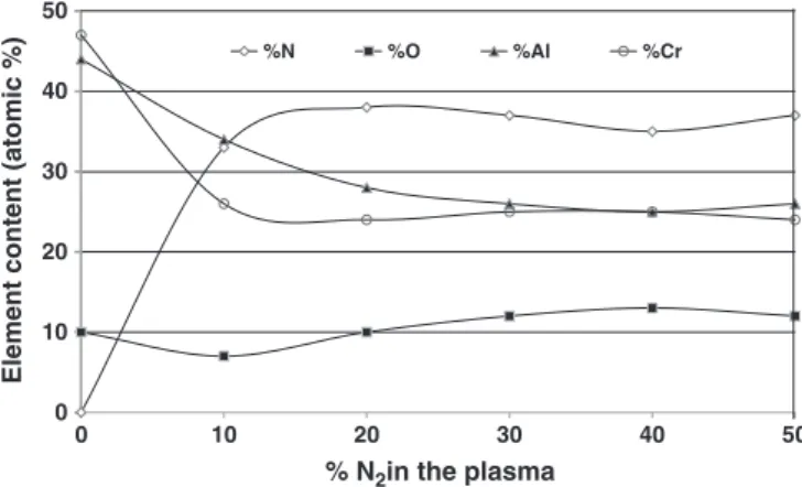
According to the EDS microanalysis, in the case of CrAlN coatings deposited from a single target (CrAlN1), above 15% of nitrogen in the plasma, we obtain a constant atomic composition of 38% of N, 25% of Al, 25% of Cr and 10% of O (which is not negligible) as shown onFig. 2. The other deposition parameters (working pressure and tar-get voltage) had no influence on the coatings' composition.
Fig. 3shows the chromium, aluminum and nitrogen atomic con-tents determined by EDS in the CrAlN films deposited from two targets (CrAlN2) as a function of the applied voltage on the Cr and Al targets. First, a negligible proportion of oxygen was detected (less than 2 at.%). We observe that the Al content increases from 0 to 30 at.%, with the Al target applied voltage. This result can be explained by the resulting increase in the Al target sputtering rate. However, be-tween−700 and −900 V, there is only a weak increase in the Al con-tent from 28 to 30 at.%. According to Ding et al.[24], for the same targets and applied voltages, chromium has a higher sputtering rate than aluminum, which can explain the increase of chromium content compared to the aluminium one for these specific deposition condi-tions at the highest target voltage. We also note a slow increase of the nitrogen content from 28 to 36 at.% with the increase of the Al tar-get applied voltage, which indicates that the Al addition is beneficial for the enhancement of CrN stoichiometry. Once the maximum Al con-tent was obtained, at around 30 at.%, wefixed the applied voltage on the Al target, and began varying the Cr one. It permitted us to obtain a maximum of 51 at.% of Al since the sputtering rate of Cr is higher than the Al, as a consequence, the Cr target voltage appears to be the decisive parameter. Applying a bias voltage of−900 V on both targets yields we obtained ternary layers of Cr0.4Al0.3N0.3.
The increase of the layers thickness can be explained by the in-crease of the applied voltage on a target or by the fact that Cr sputter-ing rate is higher than the Al one. Similar results have been obtained by Ding et al.[24].
As afirst conclusion on the composition of these CrAlN layers, we can note that the maximum Al content is around 25 at.% after stabili-zation in the case of the CrAlN1 layers while the CrAlN2 have a max-imum at 51 at.% of Al. It is also noteworthy that when we varied only the Al bias voltage we obtained 28–36 at.% of Al in the CrAlN2 coat-ings while the maximum of Al content in the CrAlN1 layers after vary-ing the nitrogen content in the plasma was around 25–35 at.% before stabilization. These results are quite similar and confirm again the main possibility to increase the Al content by the use of two targets.
Al Cr Substrate DC RF RF
Fig. 1. Schematic inside view of the RF dual magnetron sputtering chamber.
0 10 20 30 40 50 0 10 20 30 40 50
Element content (atomic %)
% N2in the plasma
%N %O %Al %Cr
3.2. XRD analyses of the CrAlN layers
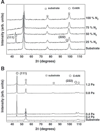
The XRD analyses were made on ground steel samples as men-tioned above in the case of the CrAlN1 layers. First, we studied the influence of the nitrogen content in the plasma: we observe a minor diffraction peak at 44° on the XRD patterns of theFig. 4A except for the coatings obtained with 25 and 50% of N2. In the case of the layer
obtained with 25% of N2, we have an intense and thin peak at 44° and a minor one at 98° not detected for the other nitrogen contents, which indicates a well crystallized phase. Unfortunately, XRD alone cannot answer whether this is a CrN in an AlN matrix, an AlN in a CrN matrix, or a ternary, quaternary system, such as pure CrAlN or CrAlNO because of the presence of 10% of oxygen. Some complemen-tary analyses (Energy Backscattered Diffraction, X-ray Photoelectron Spectroscopy, and Secondary Ion Mass Spectrometry in progress) are necessary to define which phases are present. Above 25% of N2, the diffraction peaks are less intense, and broader. This could be explained by the fact that higher nitrogen content interferes in the sputtering process and is detrimental to good crystallinity. As a con-clusion, to obtain well crystallized CrAlN coatings with a sintered Cr75Al25 target, we have to work with nitrogen content at around 25%. In a second experiment, we verified the influence of the working pressure (Fig.4B): only the intensity of the diffraction peaks at 44 and 98° varied. It seems that the optimal working pressure is 0.4 Pa. When the pressure increases, there are a lot of species in the plasma which interfere with the ones participating in the growth, decreasing their rate and energy. Below 0.4 Pa, there are not enough species and the sputtering rate is decreased as the species energy necessary to obtain a well crystallized coating. In these cases, or the grain size is too small or the layers are amorphous. Finally, the influence of the target volt-age was studied (Fig.5): the optimal voltage is the highest one. Indeed, we observe that when the target voltage increases, the inten-sity of the diffraction peaks at 44 and 98° also increases and thefilms are more crystallized. When we work at−300 V, the layers are amor-phous or composed of very small grains not detectable by XRD. The optimal target voltage is−900 V in our case.
The XRD analyses of the CrAlN2 coatings were made on silicon substrates deposited with different Al contents and are presented in
Fig. 6. A broad Cr2N (111) peak was observed on the XRD spectrum of the CrNfilm, which confirms the N/Cr ratio of 28/72 obtained by the EDS microanalysis (Fig.3). This broad peak shows that the depos-itedfilm is not well crystallized. By adding 5, 13 and 28% of Al, CrN (200) and AlN (311) diffraction peaks appeared showing that the alu-minum addition enhanced the CrNfilm crystallization. This result is in correlation with other works[24,25]. At 30 at.% of Al content, a broad peak probably coming from the presence of both CrN (200) and AlN (200) orientation appeared and the layer is well crystallized. This result was also obtained in several works[25–27]. Moreover, there is a shift of this peak to wider angles showing that CrAlNfilms contain compressive stresses, with the results already observed in a previous study[26]. This peak completely disappeared above 44 at.% of Al content where only the AlN (311) peak exists. This last peak dis-appears at 51 at.% of Al content, and is replaced by a broad AlN (002) peak indicating that the depositedfilm becomes amorphous. As a conclusion of these XRD analyses, the CrAlN1films are always well crystallized on the contrary to the CrAlN2 ones which became amor-phous for the highest Al content.
-10 0 10 20 30 40 50 60 70 80 90 100 500 700 900 0 300 500 700
Atomic content (at. %)
Applied voltage (-V) N Cr Al Al target Cr -900 V Cr target Al -900 V
Fig. 3. EDS results of the CrAlN2films obtained by varying the applied voltage on the Al or the Cr target.
40 50 60 70 80 90 100 110
Intensity (arb. units)
Intensity (arb. units)
Substrate 25 % N2 100 % N2 75 % N2 50 % N2 2θ (degrees) 40 50 60 70 80 90 100 110 2θ (degrees) substrate CrAlN (222) (111)
A
B
substrate CrAlN Substrate 0.4 Pa 0.2 Pa 0.8 Pa 1.2 Pa (222) (111)Fig. 4. XRD patterns of CrAlN1 coatings as a function of: (A) the nitrogen content in the plasma; (B) the working pressure.
20 30 40 50 60 70 80 90 100 110 120
2θ (degrees)
Intensity (arb. units)
substrate -300 V -500 V -700 V -900 V (111) (222)
3.3. Internal stresses of the CrAlN layers
In the case of the CrAlN1films, the stresses were determined by profilometry and the Newton's ring method using the Stoney's equa-tion. It is noteworthy that only the method by profilometry permits to determine if the stress is in tension or compression. We applied the same sign to the stresses obtained by both methods. We can observe onFig. 7that both methods give a similar behavior: the same curve but with a different optimum (−4 GPa in the case of profilometry and−12 GPa for the Newton's ring method). Nevertheless, these re-sults permit to determine an optimal deposition time for coatings with lower stresses. Below 40 min of deposition (layers 400 nm thick), the stresses are too high. Since we are looking for good adhe-sion of the coatings on cutting tools, we are looking for lower stresses. This occurs for coatings obtained with deposition times above 60 min (layers > 600 nm thick). Nouveau [27] obtained similar results for Physical Vapor Deposition (PVD) CrN layers compared with TiN or c-BN and explained this behavior in previous studies[27–29].
The residual stresses of the CrAlN2 coatings as a function of Cr and Al applied voltage are presented inFig. 8. The CrAlN depositedfilms have compressive stresses which vary between −1 and −3.5 GPa. Similar results have been obtained by Choi [30]. It is noteworthy that the residual stresses reached their highest value for Al content until 30 at.%, and then decreased. The increase of the residual stresses with the Al content can be explained by the increase of micro struc-tural defects causing by the substitution of Cr atoms by Al ones. Be-sides, when the Cr applied voltage decreased from−900 to −700 V (or−500 V), the Cr incident atoms lose energy which can explain
the decrease of the residual stresses by the creation of defects, such as a columnar structure, and as a consequence, the layers are less dense (Fig.10). So, the variation of the residual stresses can be explained by these two phenomena. As a conclusion, the CrAlN1 and CrAlN2 layers present compressive stresses. If we compare the stres-ses of both layers obtained in similar deposition conditions (90 min, 0.4 Pa,−700/−900 V and around 20–25% of nitrogen in the plasma), they are around 0 GPa (CrAlN1) and−1 GPa (CrAlN2) which is quite similar.
3.4. Morphology of the CrAlN layers
SEM cross section observations were carried out to determine the layers morphology. The CrAlN1 layers always present a columnar structure, as shown onFig. 9(deposition conditions: 90 min, 0.4 Pa, −900 V and 25% of nitrogen in the plasma).
Fig. 10shows the SEM cross section observations of the CrAlN2 films. It is clear that the CrN film (0% of Al) is dense and amorphous. By adding Al, thefilms present a dense (at 5 and 30% of Al), and then a columnar structure, clearly visible for 13, 28 and 44 at.% of Al. Accord-ing to the XRD analysis, we noted the appearance of AlN (311) diffrac-tion peak for thesefilms; this morphology can be explained by the formation of the AlN phase. The disappearance of the AlN (311) peak and the presence of the broad peak composed of the CrN (200) and AlN (200) ones may be the cause of the morphological modification of the CrAlN coatings obtained with 30% of Al which be-came denser. The morphology of the CrAlN coatings deposited with 51% of Al shows a dense and amorphous structure which is in corre-lation with the XRD analyses. As a conclusion, while the CrAlN1 always present a columnar structure, typical of PVD coatings, some CrAlN2films and especially the ones obtained with 5, 30 and 51 at.%
35 40 45 50 55 AlN(200) CrN(200) Cr2N(111) AlN(311) AlN(002) 51 at. % 45 at. % 30 at. % 28 at. % 13 at. % 5 at. % 0 at. % Si
Intensity (arb. units)
2θ (degrees)
Fig. 6. XRD patterns of CrAlN2 coatings as a function of Al content.
0 20 40 60 80 100 -2 -1 0 1 2 3 4 5 6 7 8 9 10 11 12 13 Stress (-GPa)
Deposition Time (min)
Profilometer Newton's Rings
Fig. 7. Stress versus the deposition time obtained with two methods for the CrAlN1 layers.
0 5 10 15 20 25 30 35 40 45 50 55 - 1 0 1 2 3 4 5 6 7 8
Residual stress (-GPa)
Al content (at. %)
Fig. 8. Residual stresses determined by 2D profilometry and the Newton's ring method vs the Al content in the CrAlN2films.
7 kV
x37000
1 µm
of Al are dense. This morphological change is correlated with the structural one in XRD (in the presence of different phases).
3.5. Hardness, Young's modulus and friction coefficient of the CrAlN films The results about the hardness, Young's modulus and coefficient of friction of the CrAlN1 coatings are summarized inTable 1. We observe the influence of the working pressure, the nitrogen content, and the target voltage. Indeed, lowering the working pressure increases both the hardness and the Young's modulus of the layers. These re-sults are in accordance with others: deposition at low working pres-sure appears to be optimal. Unfortunately, the instability of the RF discharge prevents us from working below 0.4 Pa. As a result, in our system 0.4 Pa seems to be the optimal working pressure to obtain hard coatings with a reasonable Young's modulus. The nitrogen con-tent has a lower influence on the hardness of the coatings than the working pressure. Nonetheless, decreasing the content to 10–20% im-proves both the hardness and Young's modulus. The best improve-ment of the Young's modulus is obtained for a nitrogen content of 17.5% which means that the optimal nitrogen content for hardness
and Young's modulus is about the same. These results tend to con-firm, and to complete, the previous ones obtained by XRD where we determined the optimal nitrogen content (around 25%) to obtain well crystallized coatings and now an optimal nitrogen contents of 17.5% to reach good mechanical properties. The last parameter stud-ied in the case of the CrAlN1 layers is the target voltage: whatever the deposition conditions, working at high target voltage (especial-ly −900 V) yielded the highest hardness and Young's modulus. These results confirm the previous ones concerning the optimal target voltage to obtain coatings with good mechanical properties. The results of nanoindentation tests confirm and complete the XRD analyses: when thefilms are well crystallized, they are hard. The optimal deposition conditions permitting to have well crystallized and harder coatings are a working pressure of 0.4 Pa, a nitrogen content of 17.5 to 25% and a target voltage of−900 V. Additionally, one coating was tested in pin-on-disk to determine its friction coefficient; this one was very low, 0.31, in comparison to the untreated steel and so very promising for mechanical applications.
The hardness and Young's modulus of the CrAlN2 coatings as a function of Cr and Al applied voltage are summarized inTable 2. They varied between 15 and 36 GPa and 331 and 520 GPa respective-ly. They are higher than those of the conventional Cr–N system (18 GPa and 220 GPa respectively)[31]. Similar values have already been obtained in previous studies[31,32]. The maximum values of hardness and Young's modulus were obtained for 30 and 51 at.% of Al content, this can be explained by the formation of a solid solution due to the substitution of Cr atoms by Al ones[31]. The hardness and the Young's modulus decreased at 44 at.% of Al to 15 GPa and 331 GPa respectively. Indeed, this Al content has been obtained at−700 V on the Cr target and−900 V on the Al one. So, when we change the Cr applied voltage from −900 to −700 V the energy of the incident atoms on the substrate decreases, as the number of defects created dur-ing deposition. As the hardness depends on this defects density, it de-creases consequently. So, two hardening effects occur: one is solid
0 %
5 %
13 %
x30000
0.5 µm
x20000
1 µm
x20000
1 µm
28 %
30 %
x15000
1 µm
x15000
1 µm
45 %
51 %
x20000
1 µm
x20000
1 µm
Fig. 10. SEM cross-section observations of the CrAlN2films.
Table 1
CrAlN1 coatings properties (obtained with one CrAl target). Working pressure (Pa) Target voltage (−V) N2content in the plasma (%) Hardness (GPa) Friction coefficient Young's modulus E (GPa) 0.4 700 35 19.7 – 270 17.5 22.7 – 365 900 10 25.8 – 315 17.5 23.5 – 402 25 20.3 0.31 283 35 21.4 – 307 0.8 25 8.2 – 153 1.2 6.4 – 121
solution formation and the other is the number of created defects dur-ing the deposition process.
The friction coefficient of the CrAlN2 layers only varies from 0.6 to 0.7 (Table 2) with the Al applied voltage. Similar values of the friction coefficient have been obtained in previous studies[31]. According to Bobzin et al.[1]the AlNfilms have a higher friction coefficient than CrN and CrAlN ones, so we can say that Al addition is responsible for the AlN phase presence which explains the high values of friction coefficient of CrAlN coatings. Nevertheless, these values are lower than the substrate which should be close to 1.
4. Conclusions
The aim of this work was to compare the properties of CrAlN coat-ings obtained by RF magnetron sputtering with one sintered target (Cr75Al25) versus two independent targets (Cr and Al). The above re-sults support the conclusions that the composition of the CrAlN1films is limited to a maximum Al content of around 25 at.% after stabiliza-tion while the CrAlN2 ones presented until 51 at.% of Al. These results prove the main possibility to increase the Al content significantly with two targets in comparison to only one sintered target. Besides, we observed that the CrAlN1 films are always well crystallized as opposed to the CrAlN2 ones which became amorphous for the highest Al content. Both CrAlN1 and CrAlN2 coatings present compressive stresses which are quite similar when the films are deposited in almost the same deposition conditions. Concerning the morphology of the layers, the CrAlN1 ones always present a columnar structure, typical of PVD coatings, while some CrAlN2films, and especially the ones obtained with 5, 30 and 51 at.% of Al, are dense. This morpholog-ical difference was explained by a structural one in XRD (phases in presence). Finally, the CrAlN2films present better tribological prop-erties in comparison to the CrAlN1 coatings, but this last one presents the lowest friction coefficient (0.31 compared to ~0.6 for the CrAlN2 films) which could be explained by the high hardness and Young's modulus of these coatings. Indeed, the optimal deposition conditions permitted to get a maximum hardness and Young's modulus of 26 and 310 GPa respectively in the case of the CrAlN1films while these maxima are 35–36 and 460–520 GPa respectively in the case of the CrAlN2 layers.
According to these results, it does not seem justified to work with a sintered target instead of two independent targets if the deposition system has two or more cathodes. Indeed, it has been shown that all the properties, except the friction coefficient of the films and their crystallinity, obtained with two targets are better than the ones obtained with a sintered target. Finally, the use of two targets is less
expensive, needs no particular attention, and allows better control over more parameters (especially the Al content). It permits the de-velopment of coatings with very different properties and also allows obtainingfilms with good characteristics for mechanical applications. Nevertheless, as mentioned in theIntroductionsection, this choice will depend on the kind of deposition technique and the kind of appli-cations to be developed (laboratory or industrial ones where the type and number of targets is generally imposed).
Acknowledgments
The authors would like to thank the Regional Council of Burgundy, France for its funding and Michael Walock for his help in English revisions.
References
[1] K. Bobzin, E. Lugscheider, R. Nickel, N. Bagcivan, A. Krämer, Wear 263 (2007) 1274.
[2] K. Bobzin, E. Lugscheider, A. Maes, Surf. Coat. Technol. 200 (2005) 1560. [3] H.C. Barshilia, B. Deepthi, K.S. Rajam, Surf. Coat. Technol. 201 (2007) 9468. [4] J.L. Endrino, S. Palacin, M.H. Aguirre, A. Gutierrez, F. Schäfers, Acta Mater. 55
(2007) 2129.
[5] M. Panjan, M. Cekada, P. Panjan, A. Zalar, T. Peterman, Vacuum 82 (2008) 158. [6] L. Chen, Y. Du, S.Q. Wang, J. Li, Int. J. Refract. Met. Hard Mater. 25 (2007) 400. [7] J. Creus, A. Billard, F. Sanchette, Thin Solid Films 466 (2004) 1.
[8] A. Karimi, W. Kalss, Surf. Coat. Technol. 202 (2008) 2241.
[9] X. Liu, C. Johnson, C. Li, J. Xu, C. Cross, Int. J. Hydrogen Energy 33 (2008) 189. [10] J.L. Mo, M.H. Zhu, B. Lei, Y.X. Leng, N. Huang, Wear 263 (2007) 1423.
[11] B.D. Beake, J.F. Smith, A. Gray, G.S. Fox-Rabinovich, S.C. Veldhuis, J.L. Endrino, Surf. Coat. Technol. 201 (2007) 4585.
[12] V.H. Derflinger, A. Schütze, M. Ante, Surf. Coat. Technol. 200 (2006) 4693. [13] M. Ahlgren, H. Blomqvist, Surf. Coat. Technol. 200 (2005) 157.
[14] K.-D. Bouzakis, N. Michailidis, S. Gerardis, G. Katirtzoglou, E. Lili, M. Pappa, M. Brizuela, A. Garcia-Luis, R. Cremer, Surf. Coat. Technol. 203 (2008) 781. [15] S.R. Pulugurtha, D.G. Bhat, Surf. Coat. Technol. 201 (2006) 4411.
[16] B.C. Schramm, H. Scheerer, H. Hoche, E. Broszeit, E. Abele, C. Berger, Surf. Coat. Technol. 188 (189) (2004) 623.
[17] E. Lugscheider, K. Bobzin, K. Lackner, Surf. Coat. Technol. 174 (175) (2003) 681. [18] X.-Z. Ding, C.T. Bui, X.T. Zeng, Surf. Coat. Technol. 203 (2008) 680.
[19] D. Yu, C. Wang, X. Cheng, F. Zhang, Appl. Surf. Sci. 255 (2008) 1865.
[20] G. Erkens, R. Cremer, T. Hamoudi, B.-D. Bouzakis, I. Mirisidis, S. Hadjiyiannis, G. Skordaris, A. Asimakopoulos, S. Kombogiannis, J. Anastopoulos, K. Efstathiou, Surf. Coat. Technol. 177 (178) (2004) 727.
[21] C. Labidi, R. Collet, C. Nouveau, M.-A. Djouadi, S. Nicosia, P. Beer, in: Organizing committee (Eds.), Wood machining 2004, Proceedings of the Second International Symposium on Wood Machining, Vienna, Austria, July 5–7, 2004, p. 475, Personal communication.
[22] G.G. Stoney, in: The Royal Society (Ed.), Proceedings of the Royal Society A, Mathematical, Physical and Engineering Sciences, London, United-Kingdom, May 6, 1909, 1909, p. 172.
[23] K.J. Wahl, R.R. Chromik, G.Y. Lee, Wear 264 (2008) 731. [24] X.-Z. Ding, X.T. Zeng, Surf. Coat. Technol. 200 (2005) 1372.
[25] M. Uchida, N. Nihira, A. Mitsuo, K. Toyoda, K. Kubota, T. Aizawa, Surf. Coat. Technol. 177 (178) (2004) 627.
[26] A. Kimura, M. Kawate, H. Hasegawa, T. Suzuki, Surf. Coat. Technol. 169 (170) (2003) 367.
[27] C. Nouveau, PhD Thesis, Ecole Nationale Supérieure d'Arts et Métiers, France, 2001.
[28] C. Nouveau, M.-A. Djouadi, O. Banakh, R. Sanjinés, F. Lévy, Thin Solid Films 398/399 (2001) 490, Personal communication.
[29] M.-A. Djouadi, C. Nouveau, O. Banakh, R. Sanjinés, F. Lévy, G. Nouet, Surf. Coat. Technol. 151/152 (2002) 510, Personal communication.
[30] A.E. Reiter, V.H. Derflinger, B. Hanselmann, T. Bachmann, B. Sartory, Surf. Coat. Technol. 200 (2005) 2114.
[31] X.-Z. Ding, X.T. Zeng, Y.C. Liu, F.Z. Fang, G.C. Lim, Thin Solid Films 516 (2008) 1710.
[32] G.S. Kim, S.Y. Lee, Surf. Coat. Technol. 201 (2006) 4361. Table 2
CrAlN2 coatings properties (obtained with two targets Cr and Al). Cr bias voltage (−V) Al bias voltage (−V) Al content (at.%) Thickness (μm) Hardness (GPa) Young's modulus (GPa) Friction coefficient 900 300 5 2.1 26 410 0.6 500 13 2.5 26 410 0.65 700 28 2.7 23 380 0.7 900 30 3 35 460 0.65 700 44 2 15 331 – 500 51 2.1 36 520 –