Science Arts & Métiers (SAM)
is an open access repository that collects the work of Arts et Métiers Institute of Technology researchers and makes it freely available over the web where possible.
This is an author-deposited version published in: https://sam.ensam.eu Handle ID: .http://hdl.handle.net/10985/8932
To cite this version :
Zakaria ALLAM, Sandra ZIMMERCHEVRET, Laurent LANGLOIS, Gabriel ABBA, Régis BIGOT -Statistical model of the tool/workpiece mechanical interactions in FSW - In: 2nd International Conference on Friction Stir Welding and Processing FSWP'2012, France, 20120126
-Proceedings of 2nd International Conference on Friction Stir Welding and Processing FSWP'2012 - 2012
Any correspondence concerning this service should be sent to the repository Administrator : [email protected]
Statistical model of the tool/workpiece
mechanical interactions in FSW
Zakaria Allam(1), Chevret Sandra(2), Laurent Langlois(1), Gabriel Abba(1), Régis Bigot(1)
(1) LCFC, ARTS ET METIERS ParisTech Metz, 4 rue Augustin Fresnel, 57078 Metz cedex 1 (2) Institut de Soudure, Centre FSW, 2-4 Rue Pilâtre de Rozier, 57420 GOIN
Abstract
The robotization of the FSW process is facing two challenges which are to support the amplitude of the tool / workpiece mechanical interaction generated by welding and to apply the process parameters and in particular the axial force. To design the control laws of the robot it is necessary to model the mechanical interaction between the tool and the workpiece as function of the fsw process parameters.
Keywords : Tool / workpiece interaction, FSW, Statistical laws
1 Introduction
The prediction of the mechanical efforts between the tool and the material is essential for the implementation of a robotized FSW means of production. Indeed, due to the compliance of this type of structure the trajectories of the robot should be corrected to allow the tool to follow the weld joint. Furthermore, robots are generally position controlled while the FSW tool should be force controlled along its axis. The identification of the mechanical interaction behavior between the tool and the work-piece is necessary to design the control of a robotized FSW means of production.
In this article, the evolution laws giving the tool/workpiece mechanical interaction are established statistically [1] in the case of a butt weld of two aluminium 6082 T651, 6 mm thick sheets. An experimental plan is conducted with as input parameters the three main process parameters [2]: the travel speed, the spindle speed and the axial force. For each test, three mechanical interaction
components are measured: the spindle torque, the travel force and the transverse force.
2 Results
Two types of statistical models are studied. The first one corresponds to power laws. The results obtained with this type of law well fit the evolution of the spindle torque and, to a lesser extent, the one of the travel force. However, the transverse force is not well fitted, the quadratic mean squared error being important. The analyze of the two first power law shows that the spindle torque is a function of the spindle rotation speed and the axial force. The coefficient of intercorrelation between the spindle rotation speed and the travel speed is weak. The travel force is a function depending on the travel speed and the axial force.
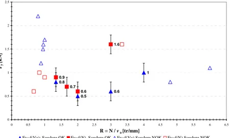
The statistical analyze shows that the transverse force seems not to be correlated to any process parameters if considered separately. For a constant axial force, the evolution of the transverse force versus the ratio rotation speed on travel speed is convex as illustrated on the figure 1.
1 0.6 0.5 0.8 0.9 0.7 0.6 1.6 0 0.5 1 1.5 2 2.5 0 0.5 1 1.5 2 2.5 3 3.5 4 4.5 5 5.5 6 6.5 R = N / va [tr/mm] Fy [k N ]
Fy=f(Va); Soudure OK Fy=f(N) Soudure OK Fy=f(Va) Soudure NOK Fy=f(N) Soudure NOK
Figure 1 : Evolution de the transverse force versus rotation speed on travel speed ratio
A simplified model of the distribution of the stress around the tool is proposed in order to explain the evolution of the transverse
force as function of the process parameters. This model is based on a temperature distribution corresponding to simplified results extracted from the litterature [3]. The parameters of the model are identified from the experimental result concerning the spindle torque and the travel force. These parameters are then kept in order to calculate the transverse force. This last one is then compared to the experimental one.
3 Conclusions
The results of the study show that the evolution of spindle torque and the travel force can be modeled by power laws of the FSW process parameters. On the other side, power law doesn’t fit well the transverse force. The evolution of this force probably comes from two phenomena:
- for high spindle speed and low travel speed, the decrease
of the ductility of the material at the back of the tool due to heating excess, the temperature reached can rise the semi solid state. This is supported by the observation of scales on the surface of the weld bead for high axial force. This causes an imbalance between the front and the back of the tool shoulder causing an increase in the transverse component of the tool workpiece effort.
- for the low value of spindle rotation speed and high value
of travel speed, an imbalance of the distribution of stress distribution around the pin of the tool between the advancing and the retreating side. This is supported by the appearance of the tunnel default for value of the process parameters closed to the considered ones.
References
[1] X. Zhao, P. Kalya, R.G. Landers, K. Krishnamurthy, Design and
implementation of non-linear force controllers for friction stir welding, Proceeding of the 2007 American Control Conference, July 2007, New-York.
[2] S. Zimmer, Contribution à l’industrialisation du soudage par friction malaxage, Mémoire de Thèse, (2009)
[3] A. Bastier, M.H. Maitournam, F. Roger, K. Dang Van, Modelling of the residual state of friction stir welded plates, Journal of material processing technology, Volume 200, Issues 1-3, pp25-37, (2008)