HAL Id: hal-02454258
https://hal.archives-ouvertes.fr/hal-02454258
Submitted on 24 Jan 2020
HAL is a multi-disciplinary open access
archive for the deposit and dissemination of
sci-entific research documents, whether they are
pub-lished or not. The documents may come from
teaching and research institutions in France or
abroad, or from public or private research centers.
L’archive ouverte pluridisciplinaire HAL, est
destinée au dépôt et à la diffusion de documents
scientifiques de niveau recherche, publiés ou non,
émanant des établissements d’enseignement et de
recherche français ou étrangers, des laboratoires
publics ou privés.
Engineering Railway Systems with an
Architecture-Centric Process Supported by AADL and
ALISA: an Experience Report
Paolo Crisafulli, Dominique Blouin, Françoise Caron, Cristian Maxim
To cite this version:
Paolo Crisafulli, Dominique Blouin, Françoise Caron, Cristian Maxim. Engineering Railway Systems
with an Architecture-Centric Process Supported by AADL and ALISA: an Experience Report. 10th
European Congress on Embedded Real Time Software and Systems (ERTS 2020), Jan 2020, Toulouse,
France. �hal-02454258�
Process Supported by AADL and ALISA: an Experience
Report
Paolo Crisafulli1, Dominique Blouin2, Fran¸coise Caron3, and Cristian Maxim1
1
IRT SystemX, Paris, France firstname.lastname@irt-systemx.fr
2 LTCI, Telecom Paris, Institut Polytechnique de Paris, France dominique.blouin@telecom-paris.fr 3
Eiris Conseil, France francoise.caron@eiris.fr
Keywords: Model-based Engineering · AADL/ALISA · Cyber-Physical Systems · Agile · ETCS.
1
Context and Motivation
The increasing automation of transportation systems has contributed to the emergence of the so-called Cyber-Physical Systems (CPS), which are computation-based systems in which computing devices, sensors, actuators and networks collaborate to monitor and control physical entities via feedback loops. To cope with the increasing complexity of such systems, engineering teams require model-based tools, because they can provide early virtual integration and verification, reuse of exist-ing models, requirements traceability and support of an incremental development process. However, these benefits can only be earned if the chosen modeling languages are expressive enough to capture all aspects necessary to perform the virtual verifications with the required confidence degree.
As stated by Peter Feiler in [7], “As an architecture language for embedded real-time systems engineering, AADL (Architecture Analysis and Design Language) was designed to be component based, capture all aspects of industrial-sized embedded systems, and support the validation through analysis and auto-generation of such systems from AADL models.” This description suits the needs of a cyber-physical systems engineering team as described above. Therefore in this paper, we report on the ability of AADL and its companion framework ALISA (Architecture-Led Incremental System Assurance) [6] to support an agile, incremental and verification-led engineering process with respect to three aspects:
– language expressivity evaluated using a typical case study of the railway industry
– capability of ALISA to establish traceability between system requirements and design, main-tain design integrity through automated verification and evaluate design alternatives with Key Performance Indicators (KPIs) charts
– finally, agility of an engineering process by reusing successful software engineering techniques such as continuous integration and verification.
This assessment has been carried out during the PST project4 on a typical CPS, the on-board
equipment of the European Train Control System (ETCS). The ETCS is a system of systems for the signaling and control of the European Rail Traffic Management System (ERTMS)5. The core
component of the on-board equipment is the European Vital Computer (EVC), which is the com-puting platform hosting the train control functions. Some of them are vital, as it is the case for the emergency breaking function.
4 https://www.irt-systemx.fr/en/project/pst/ 5
2
Positioning with regards to the State of the Art
Since its publication [8, 9], the AADL language has been mainly tested and used in domains that use real-time embedded systems.
The majority of work done with AADL is dealing with use cases from the avionics and aerospace domains. Hence, in [3] the authors describe a complete power system from an aerospace use case for which they perform a series of safety and performance analyses. In [4], a flight computer architecture is used to present a tool that makes the translation from AADL to the BIP Behavior Interaction Priority) language. The Ocarina toolset [12] was conceived for avionics real-time embedded systems and can be used to map AADL models to analysis tools (e.g. model checkers or schedulability analyzers) or to generate C or Ada code for real-time operating systems.
Use cases coming from the nuclear domain have been used in [5] for the fault analysis of a Digital Feed-Water Control System and in [13] with the scope of identifying cyber-physical attacks in a power plant.
Much less work has been devoted to its use for railway systems. In [16], an approach is presented extending AADL to model the physical world and spatial-temporal requirements of railway CPSs. In [1], the focus is on formal verification of components behavior for movement authority scenarios of Chinese train control systems. In [2], an uncertainty annex is proposed to support quantitative analysis using statistical model checking of similar systems.
3
Use of AADL for the Railway Domain
In our work, we have identified the engineering process of the aforementioned EVC to be a typical railway industry case study for the following reasons:
– In the ERA (European Railway Agency) specification, this component is constrained by a large number of non-functional requirements, mainly in terms of safety, reliability and availability. It is the core of the ETCS on-board CPS.
– These requirements often lead to choose a TMR (Triple Modular Redundant) architecture [14] to implement the EVC, which is very typical of railway embedded critical computing engineering patterns.
Although the ETCS as a whole is a CPS, the EVC is more typical of an embedded system. Even though the AADL model we created treats the entire ETCS, in this paper we present a verification scenario focusing on the EVC as an embedded system.
To meet the required very low hazard rate, this architecture uses three identical computers meant to process the same input received at time t, and to pass their output messages to a majority-voting process done by each of the computers (time t + 1). At time t + 2, the final and identical outputs will be produced, while in the case of different outputs the faulty CPU will be turned off. Figure 1 depicts the data flow and tasks involved in the TMR implementation for the needs of this work.
This execution architecture has a strong impact in terms of response-time and schedulability, which can be adverse to the EVC execution performance requirements. To better understand the execution of the EVC on the TMR platform, we separate all the existing tasks of the EVC sys-tem in two different sets. Therefore, we consider all the tasks related to the functioning (breaking, data conversion, etc;) of the system as the applications, and we name all the tasks that provide safety and availability through TMR as the middleware (inter-CPU synchronization, vote and other mechanisms). As a first observation, the more CPU consuming the middleware is, the less space the application will have to execute. Therefore, in the development process we declare a design requirement stating that the application needs at least 50% of the CPU utilization.
Figure 2 shows how the middleware and applications tasks are sequenced into an execution pipeline. It can be observed that a full pipeline cycle is reserved for the application while the mid-dleware is split in five tasks executing over three pipeline cycles:
Fig. 1. Principle of the triple modular redundant architecture
– During cycle N , the input messages are buffered in a FIFO.
– During cycle N + 1, the Input manager collects the inputs that have been buffered during cycle N and consolidates them in order for all the CPUs to provide the application with the same input data (tasks ”list” and ”conc”).
– During cycle N + 2, the Application executes.
– The Output vote (cycle N + 3) has the role to collect the application outputs (task ”list”) and to effectuate the voting procedure (task ”conc”). The output stream produced by each applications instances are checked for coherency. This evaluation allows checking the coherency of the three CPUs and prevents the platform from producing erroneous output data.
– The Output Gateway (cycle N + 4) has the role to collect the vote results and to combine them in order to produce a safe output command which will be transmitted over the network to other equipments of the entire CPS.
As it can be observed in Figure 2, the system needs almost 4 full cycles to execute the entire processing chain, starting from a new input flow subset until the corresponding output is produced. The duration of the pipeline cycle (pipeline period ) is specified in the model.
Each CPU of the TMR needs to execute identical software instances of the middleware and of the applications. These replicas need to stay coherent in order to assure both safety and availability of the system. Therefore the following requirements must be respected:
– All of the available CPUs perform the same computing cycle at the same time (slight sub-cycle jitter is tolerated).
– They operate over the same set of input data at every computing cycle.
– They all complete the execution of their internal tasks within the stated deadlines.
The main contributions of this paper consist in modeling the EVC architectures with AADL, and using ALISA for verifying and measuring trade-offs between schedulability and response time requirements on one side, and availability and reliability requirements on the other side. This is representative of the level of engineering desirable for a typical embedded system development in the railway industry. According to the AADL language conventions, we will model the previously described tasks as threads that must be allocated to a specific CPU. For a representative model of our use case, we described the hardware , software and midelleware parts in aproximatively 100 AADL components and 600 connectors to which we ad the requirements and the verification plans used by ALISA.
Fig. 2. Execution pipeline of the EVC system
Therefore, we create a complete AADL model of the above described system. This model contains a representation of both hardware and software components of the system as well as the connections between these components. The input variable of our use case is represented by the number of messages that EVC has to process. Timing properties of the middleware tasks and of the application are also declared in the model. This allows us to apply precise timing analysis on the model in order to compute the end-to-end latency of the EVC or other key performance indicators, like the total middleware execution time or the CPU utilization by the applications.
Our implementation of TMR can be adapted to changing input rate requirements through two parameters: the pipeline period (which impacts the other timing properties such as deadlines and offsets); allocation of tasks over the four available cores of the CPUs.
An advantage of modeling our use case in AADL is represented by the capacity to perform safety analysis by using fault tolerance trees. Such analysis is out of the cope of this paper, but can be a powerful tool for in domains like avionics and aerospace where safety is of high interest.
3.1 Requirements modeling with ALISA
ALISA is a set of notations and a workbench to specify structures, requirements, verification meth-ods and verification plans for systems modeled with AADL. Such verification plans can be executed incrementally throughout the system’s life cycle to produce assurance cases, in particular for its certification. The notations are combined with AADL, which then serves to specify system’s archi-tectures. The result of performing a verification activity represents evidence that the requirement is met or not. In this paper, we propose verification plans for requirements from the spectrum of performance, safety and design rules.
For our use case, we declare a set of 11 requirements to verify with ALISA. These requirements are either extracted from the ERA safety and performance requirements, or design requirements meant to assure the coherence of the model. The list of verified requirements is as follows:
– As a design good practice, all components in the model should have their ports connected (design requirement) [V1].
– All threads should be periodic (design requirement) [V2].
– The delay between receiving the emergency break signal and applying the break command shall be less than 1 second (ERA requirement) [V3].
– Delay between receiving an input data message and output data command by the EVC shall be lower than 300 ms. This can be translated as the worst case latency allowed for the system to treat incoming messages. This requirement is derived from the above ERA requirement [V4] – A safety requirement specifying that the hazard rate of EVC shall not exceed a threshold of 0.60
x 10−9 dangerous failures per hour (ERA requirement). • All CPUs of the EVC shall hold the same functions [V5]. • All CPUs of the EVC shall be of same make and model [V6]
– A design requirement to keep the incoming messages buffer (FIFO) size under control: the size of the FIFO shall be lower than 50 (design requirement) [V7].
– By design, the total latency shall be smaller than 4 pipeline periods [V8].
– A design requirement that forces the engineers to guarantee 50% of the CPU capacity for the application execution: application utilization > 50% [V9].
– The pipeline period should be divided into three sub-periods of same duration (design require-ment) [V10].
– Middleware tasks must have a budget proportional to the FIFOs size (design requirement) [V11]. For the sake of clarity we concentrate mostly on the the design and performance requirements, while the safety ones (e.g. V5 et V6) are valid by adoption of TMR design and do not get impacted by further modification of the model in the example scenario.
Although the literature on using AADL for modeling embedded systems is very rich, to our knowledge, there are no reports on the use of ALISA for industrial case studies, especially for the railway domain. We will test the requirements design capabilities of ALISA, the extension of its verification library and how it can be leveraged to produce performance KPIs dashboards to help choosing between design alternatives.
3.2 Agility
Following the SAVI (System Architecture Virtual Integration) project [11], Adventium Labs im-plemented the CAMET (Curated Access for Model-based Engineering Tools) environment 6 and evaluated the benefits of the use of software engineering practices such as continuous integration, application programming interface sharing, etc. for model integration between suppliers and an integrator using AADL [15]. However, they did not use ALISA.
In our work, we have chosen to leverage ALISA verification capabilities because it also provides requirements traceability. In addition, it can be extended with additional automated verifications that can potentially be part of a continuous integration cycle.
4
Tooling
We have integrated several AADL tools such as OSATE7, AADL Inspector8 and Resolute[10] to
support our process centered on ALISA. The role of these tools and the way they have been used is detailed further (Section 5.2). In addition, we have developed comprehensive configuration manage-ment using mainstream source control tools such as repo9and git10. Finally, the ALISA verification
process has been used as the core of a continuous integration environment implemented with Jenk-ins11. 6 https://www.adventiumlabs.com/our-work/products-services/model-based-engineering-mbe-tools 7 http://osate.org/ 8 https://www.ellidiss.com/products/aadl-inspector/ 9 https://source.android.com/setup/develop/repo 10https://git-scm.com/ 11 https://jenkins.io/
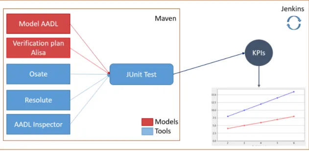
The verifications are executed as JUnit 12 tests. The entire system is compiled and executed by Apache Maven 13. Figure 3 depicts the elements (tools and models) which form our verification environment.
Fig. 3. The continuous engineering environment design for requirements verification with ALISA.
5
Summary of Results
5.1 Expressivity for the Railway Domain
N-Modular redundancy is often used in the railway domain to deal with safety, reliability and availability requirements. In the PST project, the ability of AADL to model the TMR architecture was at stake. AADL proved to be well suited to model the different views involved in our process (functional, software and execution platform). The language has the constructs required to support traceability between views: component bindings, refinement and extension. These features helped modeling the TMR architecture starting from a first functional model and refining it all the way down to precise software and hardware models ready for code-generation and deployment.
5.2 ALISA
Analyses An advantage of using the AADL language for embedded systems modeling comes from its analysis capabilities, leveraged by ALISA as verification activities. We present our results for three kinds of analysis applied to our case study:
– Structural analyses allow checking the correctness of a model with respect to the structure of hardware and software. In our case this is achieved using the Resolute [10] language to express design rules and structural constraints. We used Resolute to verify key features of the TMR design: the functions shall be redounded over the three CPUs and the CPUs type shall be the same.
12https://junit.org 13
– Response time analyses are required for the certification of embedded systems such as the EVC. This ensures that critical functions (e.g. emergency braking) can be executed on time. Such analyses were performed using the OSATE latency analysis plugin.
– Scheduling analyses were used in order to estimate the impact of the middleware TMR func-tions on the core application funcfunc-tions. We used for this purpose the AADL Inspector tool.
Traceability ALISA provides requirements modeling and traceability from the requirement(s) to the component(s) satisfying the requirement(s): each requirement must be linked to a model com-ponent and some verification activities must be linked to each requirement. In particular, we have experimented the ability to decompose and refine some ERA safety and response time requirements for the EVC.
Design KPIs With ALISA, requirements can be expressed as verifiable predicates. These predi-cates are written as arithmetic expressions. We found that these expressions can also be leveraged to compute design KPIs, in order to support decision between design alternatives and report the evolution of the design in terms of performance. The captured KPIs for our use case are split into groups according to what they are meant to measure, and to the relationships with the other KPIs in their group. Therefore, the 5 main groups are:
– Input Message Rate contains one KPI representing the number of messages that the EVC must process in a second.
– Verification results contains three KPIs: the number of successes, failures and errors obtained from the verification process
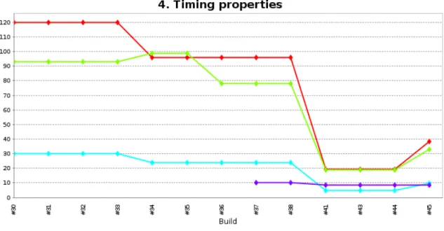
– Timing properties contains a series of values related to the timing behavior of the system. They are: the to-end latency of the system’s execution chain, the upper bound of the end-to-end latency, the pipeline period and the total middleware execution time.
– FIFO size contains the number of messages that must be buffered before being sent to the middleware for processing. Here, the maximum allowed FIFO size and the required FIFO size are saved as KPIs.
– The application utilization contains the minimum expected application utilization and the utilizations achieved by the single core design and by the multi-core design.
Agility: Continuous Integration and Verification The ALISA framework has been designed to run within the Eclipse Integrated Development Environment. This was a serious limitation for its use in a continuous integration environment. Therefore, we leveraged the ability of the Tycho
14 Apache Maven plugin to run headless Eclipse plugin tests. We also provided charts to report its
execution results, in order to deliver them as outputs of the continuous integration process. The main benefit of continuous integration and verification is to provide frequent incremental team-wise feedback on changes published by contributors, be it in terms of requirements, design or verification activities. Another benefit is that this approach allows us to record history and milestones of the project, with their associated design KPIs values.
5.3 Continuous integration scenario
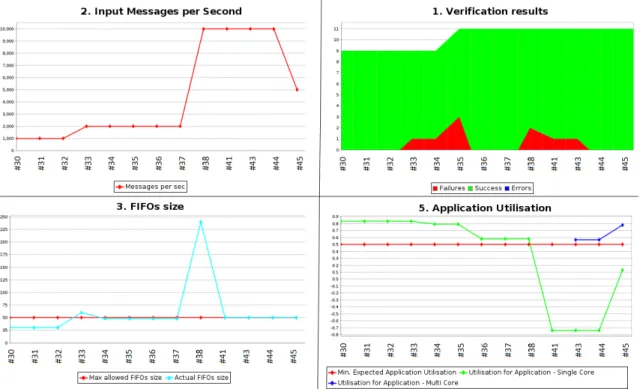
In order to better illustrate the functioning and result of the integration process, we describe a de-velopment scenario containing changes on requirements, the corresponding engineers reflections and improvements of the model, as well as the KPIs that are produced at every build of the project. The evolution of the project can be seen in figures 4 and 5. The X-axis represents the builds correspond-ing to a step in the development, identified by a build number. The Y-axis represents the KPI value.
14
Fig. 4. Graphical results of the continuous integration process
All KPIs corresponding to a step in the development are dispatched among the five plots. In Figure 4, we can observe in the upper left part the main varying requirement of our use case, the input message rate, and the way its modifications influence the other parameters and the further changes. For our scenario, we present 11 builds of the use case. The starting point is chosen such that it expresses an evolved version of the project, while previous versions which contains the initial efforts of development are intentionally not presented for the sake of clarity. In the scenario description we will refer to one version of the project as a build and we will reference it by its number. As it can be seen from the resulting plots, the counting starts with build number 30 and some of the builds that are not representative to our experiment are omitted (e.g.: #39, #40 and #42), while builds #31 and #32 are identical to build #30 in order to give us a starting basis and a better shape of the resulting plots.
#30 The initial scenario consist of the systems receiving inputs with a frequency of 1000 messages per second. Initially, we take in consideration only the first nine verifications (V1 to V9) from the above mentioned verification plans. The application is executed on a single core and the initial FIFO size is of 25 while the available utilization for the application is of 82% (Fig. 4, bottom-right) . The application utilization in the multi-core case is not computed since at this stage there is no need for more computation power. In the timing results, we plot the pipeline period which is extracted from the model and the end-to-end upper bound which must be equal to 4 times the pipeline period, by design (see Fig. 2). The end-to-end response time is computed using OSATE’s timing analysis plugin and we can observe that it stays under the computed upper bound.
#33 As a first evolution, we want to see how the system reacts when the message rate is doubled (increased to 2000 messages per second - in Figure 4 top-left). This is an intermediary step towards the frequency of 10000 messages per second, our final performance goal. As a result of the modification, the environment registers one failed verification: the FIFO size increases to 60
Fig. 5. Timing properties on multiple build versions of the PST project
and exceeds the maximum allowed size, therefore failing requirement V7 (Fig4 bottom-left and top-right).
#34 In the effort to correct the model and pass all the verification tests, we reduce the pipeline period from 30 to 24 (Fig. 4 bottom-left). This allows for the FIFO size to fit under its max allowed size (50) and make the V7 requirement pass. Nevertheless, due to this modification the response time increases while the maximum upper bound decreases (Fig. 5) and the V4 requirement fails (Fig. 4 top-right). We realize that, for our model, the timing properties of midleware tasks must be in concordance with the pipeline period. The offsets of the input manager and output vote must represent two thirds of the pipeline period, while the offset and deadline of the gateway must be one third of the pipeline period. As a consequence we add a new verification rule (V10) specifying these constraints. Another observation made during this build is that the middleware must have a budget proportional to the number of messages in the FIFO (FIFO size). Therefore, the verification rule V11 is added at this point.
#35 Requirements V10 and V11 are added, their verifications fail, raising the number of failures to 3 (Fig. 4 top-right).
#36 The middleware timing properties and budget are corrected in the model, in order to respect the previous added requirements. As a result, all verifications pass and the end-to-end response time is under the allowed upper bound. We realize at this point that it is necessary to plot the total middleware execution time. Therefore, at build #37 the corresponding KPI is plotted in figure 5 for the first time.
#37 Define and plot the KPI corresponding to the middleware total execution time.
#38 The final technical goal is to manage to process 10k message per second. Therefore, we decide to update the message rate value (Fig. 4 top-left). As it happened before, the FIFO size verification V7 and the middleware budget verification V11 fail to pass (Fig. 4 top-right).
#41 As a consequence, we reduce the pipeline period to 4800 µs in order to reduce the FIFO size (highest value that satisfies the formula F IF Osize = P ipelineP eriod × M essageRate), we
increase the midleware budget and we reduce proportionally the middleware offsets and deadline to avoid failure of verification V10. As a result, we keep the response time under control and the previously seen verification pass, but V9 fails (Fig. 4 top-right) and the value for the single core application utilization becomes negative (Fig 4 bottom-right), which means that a single core cannot support the desired input rate.
#43 The use of multi-core becomes necessary, hence at this build we create a multi-core design. We save the corresponding CPU utilization KPI and, in the lower right part of Figure 4, we can observe the application’s utilization for multi-core (and single core). The V9 still fails since its verification still relies on the utilization of the single core design (Fig. 4 top-right) .
#44 We change the V8 verification in order to take into account the multi-core design and not the single core one. Nevertheless, we continue to plot the utilization for both single and multi-core in order to see how they compare. At this point, no failure occurs and we reach the technical goal of processing 10k messages per second.
#45 We realize that a system with the timing properties of build #44 is able to work at a message rate of 10k but the application will have an available utilization of 54% per core and in more a realistic implementation, where migration and preemption costs will count this value might decrease. For this we add a final build where we decrease the message rate to 5000 and adapt the rest of the model accordingly to the before mentioned verifications (pipeline period, offsets, budget etc..).
6
Conclusion and future work
Our experiment results in a showcase of how AADL and ALISA can support an agile architecture-centric development process for a typical embedded system in the railway domain: continuous verifi-cation maintains the design within the solution space shaped by the set of requirements, while KPIs computation and charting qualify its evolution and alternatives over time, in terms of performance. ALISA is currently still under stabilization, hence its usage cannot be recommended for an engineering team facing hard delivery deadlines.
Nevertheless, this experiment illustrates how the AADL ecosystem of companion languages and development environments is evolving, opening the way to agile engineering of highly constrained systems, such as critical systems requiring a certification process.
6.1 Future work
By using tools like RAMSES15, a next step from our work is to achieve code generation. A fist step
in this direction is to generate configuration tables from the model (with ALISA) to be further used in a the application implementation.
Another future work relays around the verification of safety requirements. For that, we consider the use of the Error Model annex (EMV2) which should allow us to create fault trees and to perform fault impact analysis, applied to our TMR design.
In order to validate our method, futher testing on models coming from various domains (avionics, cybersecurity, etc.) can be considered.
We have addressed a model dealing with a dozen requirements. Industrial sized projects may have to deal with thousands of requirements. Therefore questionning the scalability of this approach is crucial. By design, Alisa offers the possibility to have an incremental verification: a set of verifications can be bundled with the verified package or set of packages, then reused in a wider system design. Therefore, it would be interresting to study how continuous integration can leverage this, in order to limit the verification execution to the packages that have been changed and their transitive dependencies.
15
References
1. Ehsan Ahmad, YunWei Dong, Brian Larson, JiDong L¨u, Tao Tang, and NaiJun Zhan. Behavior Modeling and Verification of Movement Authority Scenario of Chinese Train Control System using AADL. Science China Information Sciences, 58(11):1–20, 2015.
2. Yongxiang Bao, Mingsong Chen, Qi Zhu, Tongquan Wei, Frederic Mallet, and Tingliang Zhou. Quantita-tive Performance Evaluation of Uncertainty-aware Hybrid AADL Designs using Statistical Model Check-ing. IEEE Transactions on Computer-Aided Design of Integrated Circuits and Systems, 36(12):1989– 2002, 2017.
3. Marco Bozzano, Alessandro Cimatti, Joost-Pieter Katoen, Viet Yen Nguyen, Thomas Noll, and Marco Roveri. Safety, Dependability and Performance Analysis of Extended AADL Models. The Computer Journal, 54(5):754–775, 2010.
4. M Yassin Chkouri, Anne Robert, Marius Bozga, and Joseph Sifakis. Translating aadl into bip-application to the verification of real-time systems. In International Conference on Model Driven Engineering Languages and Systems, pages 5–19. Springer, 2008.
5. Josh Dehlinger and Joanne Bechta Dugan. Analyzing dynamic fault trees derived from model-based system architectures. Nuclear Engineering and Technology, 40(5):365–374, 2008.
6. Julien Delange, Peter Feiler, and Neil Ernst. Incremental life cycle assurance of safety-critical systems. 8th European Congress on Embedded Real Time Software and Systems (ERTS), 2016.
7. Peter H Feiler and David P Gluch. Model-based Engineering with AADL: an Introduction to the SAE Architecture Analysis & Design Language. Addison-Wesley, 2012.
8. Peter H Feiler, David P Gluch, and John J Hudak. The architecture analysis & design language (aadl): An introduction. Technical report, Carnegie-Mellon Univ Pittsburgh PA Software Engineering Inst, 2006.
9. Peter H Feiler, Bruce A Lewis, and Steve Vestal. The SAE Architecture Analysis & Design Language (AADL) a Standard for Engineering Performance Critical Systems. In 2006 IEEE Conference on Com-puter Aided Control System Design, 2006 IEEE International Conference on Control Applications, 2006 IEEE International Symposium on Intelligent Control, pages 1206–1211. IEEE, 2006.
10. Andrew Gacek, John Backes, Darren Cofer, Konrad Slind, and Mike Whalen. Resolute: an Assurance Case Language for Architecture Models. In ACM SIGAda Ada Letters, volume 34, pages 19–28. ACM, 2014.
11. Jorgen Hansson, Steven Helton, and Peter Feiler. ROI Analysis of the System Architecture Virtual Integration Initiative. Technical report, Software Engineering Institute, 2018.
12. Jerome Hugues, Bechir Zalila, Laurent Pautet, and Fabrice Kordon. From the Prototype to the Final Embedded System using the Ocarina AADL Tool Suite. ACM Transactions on Embedded Computing Systems (TECS), 7(4):42, 2008.
13. Mariam Ibrahim and Qays Al-Hindawi. Attack graph modeling for nuclear power plant. In 2018 10th International Conference on Electronics, Computers and Artificial Intelligence (ECAI), pages 1–6. IEEE, 2018.
14. Robert E Lyons and Wouter Vanderkulk. The use of Triple-Modular Redundancy to Improve Computer Reliability. IBM journal of research and development, 6(2):200–209, 1962.
15. Tyler Smith, Rand Whillock, Robert Edman, Bruce Lewis, and Steve Vestal. Lessons Learned in Inter-Organization Virtual Integration. SAE Technical Paper 2018-01-1944, 2018.
16. Lichen Zhang. Modeling Railway Cyber-Physical Systems based on AADL. In 19th International Conference on Automation and Computing, pages 1–6. IEEE, 2013.