The technical challenges of the Solar-Orbiter EUI instrument
Jean-Philippe Halain
a*, Pierre Rochus
a, Thierry Appourchaux
e, David Berghmans
b, Louise Harra
d,
Udo Schühle
c, Frédéric Auchère
e, Andrei Zhukov
b, Etienne Renotte
a, Jean-Marc Defise
a, Laurence
Rossi
a, Karl Fleury-Frenette
a, Lionel Jacques
a, Jean-François Hochedez
b, Ali Ben Moussa
aCentre Spatial de Liège, Université de Liège, Liege Science Park, 4013 Angleur, Belgium
b
Royal Observatory of Belgium, Avenue Circulaire, Uccle, Belgium
cMax-Planck-Institut für Sonnensystemforschung
,Lindau, Germany
d
Mullard Space Science Laboratory, Surrey RH5 6NT, UK
eInstitut d'Astrophysique Spatiale, Orsay, France
ABSTRACT
The Extreme Ultraviolet Imager (EUI) onboard Solar Orbiter consists of a suite of two high-resolution imagers (HRI) and one dual-band full Sun imager (FSI) that will provide EUV and Lyman-α images of the solar atmospheric layers above the photosphere.
The EUI instrument is based on a set of challenging new technologies allowing to reach the scientific objectives and to cope with the hard space environment of the Solar Orbiter mission.
The mechanical concept of the EUI instrument is based on a common structure supporting the HRI and FSI channels, and a separated electronic box. A heat rejection baffle system is used to reduce the Sun heat load and provide a first protection level against the solar disk straylight. The spectral bands are selected by thin filters and multilayer mirror coatings. The detectors are 10µm pitch back illuminated CMOS Active Pixel Sensors (APS), best suited for the EUI science requirements and radiation hardness.
This paper presents the EUI instrument concept and its major sub-systems. The current developments of the instrument technologies are also summarized.
Keywords: Extreme Ultraviolet Imager, Full Sun Imager, High-Resolution Imager, Solar Orbiter, Transmission Filter,
APS detector, Bandpass coating
1. INTRODUCTION
The Solar Orbiter mission [1],[2],[3], part of the Cosmic Vision Science Program of European Space Agency (ESA), to be launched in 2017, is devoted to the Sun observation. From its unique vantage point in an elliptical orbit around the Sun, and approaching as close as 60 solar radii, Solar Orbiter will provide unprecedented close-up and high-latitude observations of the Sun.
The Extreme Ultraviolet Imager (EUI) instrument was selected as part of the scientific payload of the Solar Orbiter mission. The EUI instrument and the scientific rationale are summarized in previous papers [4],[5],[6],[7],[8],[9]. The EUI development is lead by the Centre Spatial de Liège (Principal Investigator) within a consortium including the Royal Observatory of Belgium (ROB), the Institut d’Astrophysique Spatiale (IAS), the Institut d’Optique (IO), the Max Planck Institute for Solar System Research (MPS) and the Mullard Space Science Laboratory (MSSL).
2. EUI INSTRUMENT OVERVIEW
The EUI instrument is composed of two high-resolution imagers (HRI), one at the hydrogen Lyman-α line and one extreme ultra-violet (EUV) dual band working alternatively at 174 Ǻ and 335Ǻ passbands; and one dual band full-sun imager (FSI) working alternatively at the two 174 Ǻ and 304 Ǻ passbands.
The HRI channels use a two-mirrors Ritchey–Chrétien off-axis optical system, and the FSI uses a single mirror off-axis Herschelian system[4]. The normal-incidence telescopes are in co-alignment and operate independently. Their mirrors
have optimized coatings for FUV or EUV reflectivity in each passband. The spectral selection is complemented with filters and filter wheel rejecting the visible and infrared radiation.
Figure 1 shows the functional diagram of the HRI and FSI telescopes, including the front filter and its protection mechanism (door) and entrance baffle, the EUV filter wheel mechanisms and telescope (i.e. mirrors), the detector and proximity electronic acquisition chain, and the common electronic box.
HRI dual EUV
HRI 1216
FSI dual EUV
Entrance baffle Entrance baffle Entrance baffle
EUI structure bench
Detector Detector Detector FEE FEE FEE Heat Shield Entrance filter Entrance filter Entrance filter DPU PSU filter wheel S/C power HK, data HV PS Door mechanism TC Door mechanism
EUI common electronics box
filter wheel
Door mechanism
Figure 1. EUI functional diagram
Table 1 lists the intended temporal and spatial resolutions, field-of-view (FOV) as well as passbands of the EUI instrument.
Table 1. EUI main parameters
After descope Parameter Values
Dimensions • Optical bench • CEB
• 550x175x785mm
• 200mm x 300mm x 250mm Mass (including margins) 18.20kg (proposal 20.77 kg) Nominal power consumption 28 W
Telemetry 20 kb/s
Passband centre 174 Å and 304 Å alternatively
Field of View 5.2 arcdeg × 5.2 arcdeg
Angular resolution (2 px) 9 arcsec FSI 174/304
Typical cadence 600 s
Passband centre 174 Å and 335 Å alternatively
Field of View 1000 arc sec square
Angular resolution (1 px) 0.5 arcsec HRI 174 / 304
Typical high cadence 2 s
Passband centre 1216 Å
Field of View 1000 arcsec square
Angular resolution (2 px) 1 arcsec EUI
HRI Lyman-α
The EUI channels are mounted on a common optical bench structure (Figure2) supported by a set of dedicated mounts. The optical bench structure is made out of a CFRP sandwich panel with an aluminum honeycomb core for stiffness and thermal stability; and the optical channels are covered by CFRP facesheet panels. The common electronics box (CEB) is a separate unit (Figure3) providing control of the mechanisms (filter wheels and doors);, containing the processing unit, and ensuring the electrical interface with the spacecraft.
The mechanical configuration has been improved to fit the spacecraft volume constraints. The mounts will minimize thermal and mechanical couplings between EUI and platform, and provide sufficient stiffness to guarantee a sufficiently high first eigenfrequency.
Figure2. EUI optical bench configuration
Figure3. EUI common electronic box
3. TECHNOLOGICAL CHALLENGES
Solar Orbiter mission raises a number of technical issues, including to its payload[1], due to the proximity with the Sun. The EUI instrument is built on top of a few challenging technologies which will guarantee its success. Technological developments are thus ongoing to assess the various critical elements of the EUI design:
- Multilayers coatings - EUV detectors - Heat rejection baffles - Transmission filters - Data processing
3.1 Multilayers coatings
The HRIEUV and FSI channels are based on innovative multilayer coatings (Figure 4). For HRI, the coating will allow the transmission of 2 bands centered on 174 Å (Fe X) and 335 Å (Fe XVI); for FSI, it will allow the transmission of 2 bands centered on 174 Å (Fe X) and 304 Å (He II); with the rejection of several bright unwanted spectral lines (e.g. Fe XII 195 Å and Fe XVI 335 Å).
These multilayers are undergoing an extensive ageing study to be qualified for the Solar Orbiter misison. The coatings make use of barrier layers to stabilize the multilayer structure. Thermal cycling between -50°C and + 70°C and exposition to warm water vapor have demonstrated that these new multilayers are very stable and should not degrade during the mission. For example, no variation in reflectivity was found after testing on the 304 Å B4C/Mo/Si coating produced for the Herschel NASA sounding rocket[10]. These studies will then be complemented by irradiation tests under proton and neutron beams to ensure that the optics will not degrade during the mission lifetime.
The Lyman-α channel mirrors use proven technology for the coatings of the primary and secondary mirrors. The Al/MgF2 (aluminum/magnesium fluoride) coating provides reflectivity at 1216 Å over 75%. This optical design provides a high throughput by using a narrow-band and a broadband interference filter on MgF2 substrate to isolate the spectral line at 1216 Å (that is moreover the brightest UV line of the solar emission spectrum).
10 15 20 25 30 35 40 0.1 0.2 0.3 0.4 0.5 0.6 0.7 Measurements Simulation Reflectan ce / T ran sm ittanc e Wavelength (nm) Al Al/Mg/Al Zr 10 15 20 25 30 35 40 0.001 0.01 0.1 1 R ef lect ance / Transmit tance Wavelength (nm) Al Al/Mg/Al Zr
Figure 4: Transmittances of the front and focal plane filters and reflectance of dual passband 174/304 Å multilayer
coating. Left: Linear scale, right: logarithmic scale showing the extinctions. Black curves: theoretical reflectances, blue dots: measurements. Green, purple and red curves: entrance Al filter, focal plane Zr and Al/Mg/Al filters.
3.2 EUV detector
The detectors are back-thinned CMOS Active Pixel Sensors with 2k x 2k format for HRI channels and 4k x 4k format for the FSI, providing a pixel resolution of 0.5 arcsec and 4.5 arcsec respectively.
A development named APSOLUTE, for APS Optimized for Low-noise and Ultraviolet Tests and Experiments, has been started in 2009 with the CMOSIS N.V. Company, and will result in a 256x256 sensor containing 16 test pixel variants organized in blocks of 64x64 pixels, and a 1024x1024 sensor containing the best guess pixel variant. The prototype detector requirements are listed in Table 2. These detector prototypes will be tested in EUV and under radiation by the end of 2010. The objective is to demonstrate the suitability of the back-illuminated thinned CMOS-APS technology as very low noise EUV detector and to confirm radiation tolerance of APS. These variants contained in the prototypes will then serve to select the best pixel design to be used for the flight devices.
Table 2. EUI detector requirements
Parameter Requirement Unit Comment
Pixel pitch 10 µm 64 x 64 for variants of prototypes, 1k x 1k best guess variant prototype 2k x 2k for HRI and 4k x 4k for FSI
QE x FF > 50 % In the 10-40 nm range (BOL conditions)
Readout noise < 5 e- RMS Target: 1e- RMS after CDS, with possibility to operate at -40°C
Pixel saturation charge > 80 ke- Possible trade off with read out noise level and NDR FPS cadence
MTF / optical crosstalk 50 / 10 % @1Nyq. @ 20 nm, crosstalk is charge leakage in neighbouring px Non-linearity (p-p) < 2 Max 1% deviation from linear fitted curve
Non-linearity homogeneity/stability < 0.1 % Across pixels
Cadence > 1 FPS For sub-frames
Sensor Interface Analog External ADC
Radiation hardness >50 krad (Si) Operable after 1Mrad (Si). SEL and SEU tolerant Operational T° range -60 / +50 °C
The required low noise and high dynamic range are obtained by combining multiple readouts on low and high gain output channels. The EUV sensitivity is obtained by back-thinning a processed Silicon On Insulator (SOI) wafer, with epitaxial layer thickness of 3um, on which the CMOS circuits are deposited (0.18 CIS process).
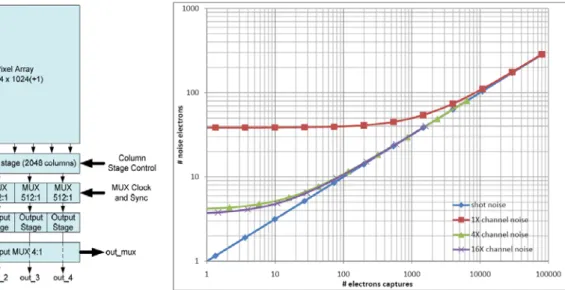
The 1k x 1k prototype block diagram is shown in Figure 5, and the expected noise versus integrated electrons is shown on Figure 6 obtained using adaptive gain. Gains up to 16 x are possible in the column gain stage. The four column multiplexer blocks multiplex all 2048 column data to four analog channels. The output multiplexer multiplexes the 4 analog channels to a single output channel. A temperature sensor is also foreseen and will be read out over an SPI interface.
In order to achieve sensitivity in the 10-40 nm range, the sensor needs to be illuminated from the backside, so it needs to be backside thinned. When the wafer processing is finished, the wafers will be diced and placed into a custom JLCC-84 package with enlarged cavity.
Figure 5. ASPOLUTE 1kx1k block diagram Figure 6. Noise chart The Lyman-α detector will use the same sensor and
readout electronic circuits. However, for better sensitivity at the Lyman-α wavelength, and for better suppression of solar continuum outside the filter pass band, the sensor will be mated with an image intensifier. The Lyman-α channel has indeed no metal filters like the EUV channels providing sufficient blocking of visible Sun light, but interference filters which need additional visible light blocking.
This is accomplished by a blocking filter inside the MCP-intensifier, making it a solar-blind detector. The intensifier will use multichannel plates with a photocathode coating and the anode will be coupled to the sensor with a fiber optic taper, to reduce the image size to the sensor size (Figure 7). A breadboard model of such detector has been built (Figure 8) and similar units have been successfully tested on NASA rocket experiments (RAISE, UNIS). Another prototype is under development for mechanical design space qualification.
.
KBr coating photocathode
Mechanical I/F structure
Figure 8. Development of an I-APS detector
3.3 Heat rejection baffles
The heat protection of the EUI HRI channels is based on reflective baffles to limit the heat load entering the instrument. The HRIs entrance baffles are designed to reject a maximum of the incoming sunlight, i.e. more than 65% even for large offset angles of the spacecraft pointing. The FSI entrance baffle is black inside, and simply absorbs the low power incoming through its small entrance pupil. The heat load absorbed in the entrance baffles is evacuated to space by a thermal link towards a secondary, passively cooled radiator of the spacecraft. The EUI baffles are completed by a thermal diaphragm and a front mirror, located between the spacecraft heat shield and the baffles, to reduce the heat load on the area surrounding the entrance pupils.
The design of the HRI entrance baffles is based on a spherical heat rejection mirror (HRM) placed at the level of the entrance filter, at a distance of 500 mm of the 30 mm Ø entrance pupil, and on the specular reflectivity of the entrance filter. Considering the solar limb field of view (± 72.7 arcmin) to which is added a maximum of 1.25 arcdeg of spacecraft off-pointing capability, the HRM diameter is 73 mm diameter, but the space between the HRM edge and the light beam going from the primary mirror to the secondary mirror would then be too small. The HRM diameter has thus been reduced to 61.7 mm, with curvature radius of 500 mm. A specific reflective baffle has been added to reject the heat load out of the baffle through the entrance pupil. The baffle also rejects the light reflected by the filter.
Ray tracing analyses (ASAP™, ESARAD™) showed that the incoming solar rays are reflected outside the baffle with at most three reflections, for an off-pointing angle up to 1.25 arcdeg (Figure 4). A rejection rate of 77% is computed for a zero off-pointing (78.2% for an off-pointing of 1.25 arcdeg) with a 90% reflection coefficient on the HRM and 80% on the cone + cylinder.
The rejection rate highly depends on the filter absorption assumed in the model, and baffle internal reflectivity.
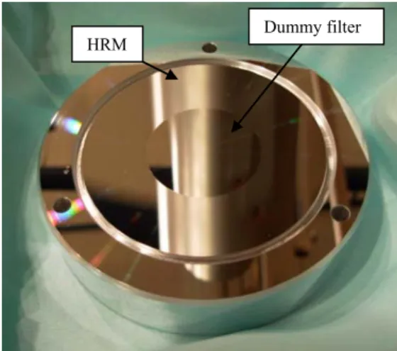
In order to validate the thermo-optical model of the HRI entrance baffle, a prototype has been manufactured and tested in CSL facilities (Figure 10). The diffuse and specular reflectivities of the HRM/dummy filter and the tube/cylinder have been measured in order to correlate the ray-tracing model with the prototype. Early tests of the baffle prototype assembly show a good correspondence with the model (Figure 9 shows measurement with a 0.45 arcdeg divergence beam. The deviation at large off-pointing angles are due to the measuring device beam that will be improved).
Figure 9. HRI entrance baffle rejection (measured vs. theoretical)
25% 35% 45% 55% 65% 75% 85% 0 0.2 0.4 0.6 0.8 1 1.2 1.4 1.6 Offpoint [arcdeg] R e ject ion [ % ] Test Model
Figure 10. HRI entrance baffle prototype
3.4 Transmission filters
At the end of the entrance baffles, the light enters the instrument through entrance filters. The HRIEUV and FSI channels are using aluminum filters that suppress most of the UV, visible and IR counterparts of the solar radiation, which is of primary importance to avoid over-heating the primary mirror. The HRILya entrance filter is a broad-band interference filter which rejects visible and infrared light as well as EUV and X-rays.
These entrance filters are subjected to a high solar flux that needs to be diverted to avoid filter overheating. Additionally, the EUV filters are very thin (typically 1500Ǻ) and thus require a support structure to withstand the launch mechanical and acoustic loads, with minimal optical artifacts.
Band selection filters are also used in the HRIEUV and in the FSI channels to select one or the other of the two bands reflected by the multilayer mirrors. These EUV filters are also very thin and mounted on filter wheels (Figure 11). They have much lower thermal loads than the entrance filters but will be subjected to high acoustic and mechanical loads. A narrow-band filter is used in the HRILya to isolate the Lyman-α line in the solar spectrum with 95% spectral purity.
Figure 11. FSI filter wheel positions (174, 304, no light).
Baseline materials identified for the EUV filters are Al for the entrance filters, and Al/Zr for (short wavelengths) and Al/Mg/Al (longer wavelengths) for the band selection filters. Such filters are available commercially with long flight heritage.
Specially designed entrance filters are however required to sustain the high thermal load they will have to endure. A custom mesh and grid support is therefore considered. The supporting structure (mesh and grid) will be made, in-house, with an electrolytic process. A growth initiating layer (copper) is deposited on the multilayers filter membrane with a manufacturing guide that can have any shape (hexagonal for example). The grid material (Nickel) is then grown within the guide that is removed at the end of the process. Figure 13 shows such a grid prototype.
The development of multilayers thin film filters with better performances (spectral selection and mechanical strength) has also been initiated for the band selection filters (Figure 12). The total material thickness is equivalent to a standard filter, but the multiplication of interfaces (periodic structure of 2 materials) prevents damages from propagating through the filter membrane. The fabrication process is based on deposition of multilayer on Si wafer, electrolytic deposition of grid and etching of Si wafer. These filters will also be reinforced by custom mesh grids with optimized aspect ratio and thickness, and with choice of material to minimize differential expansion and enhance thermal conductivity from filter to external fixation.
Figure 12. Multilayer filters
Figure 13. Filter grid prototype
Various foil filter support configurations are currently analyzed, including the addition of a cross providing additional stiffness and conductivity. Thermal models have been realized but strongly depend on the filter thermal properties. Next step is to perform conductivity and thermo-optical measurements on such filters to improve the models. Figure 14 shows a typical entrance filter temperature distribution without supporting structure, with a 70-line per inch Nickel mesh grid, and with combined mesh grid and 1-mm thick aluminum cross.
Figure 14. HRI entrance filter temperature computations
0 50 100 150 200 250 300 350 400 450 500 550 600 0 0.002 0.004 0.006 0.008 0.01 0.012 0.014 0.016
Distance from filter center [m]
T e m peratur e [° C] No mech support Mesh grid Mesh grid + cross
3.5 Data processing
In view of the large amounts of data generated by EUI telescopes (FSI 4k x 4k at 600 s cadence and two HRI 2k x 2k up to 0.2 s cadence) and limited telemetry of 20.5kbps over 30 days per orbit, the instrument needs to be equipped with on-board data processing including compression, processing and data reduction.
- Pre-processing tasks before compression degradation for quality improvement of compressed images and content analysis of images (hot/bad pixel removal, calibration and denoising, region of interest computation, trigger event detection, etc.)
- Post-processing: image and sequence selection, observation programs and image prioritization based on image descriptors
To achieve this, hardware implementation is the best solution to alleviate CPU tasks coping with high data transfer rate. A dedicated FPGA based on JPEG2000 compression software and other processing algorithms is planned to be used. Dedicated development projects have been initiated to demonstrate the suitability of such hardware implementation of the compression and data processing algorithms. A first project has validated the JPEG2000 implementation in a commercial Virtex 5 FPGA for a frame rate up to 0.1 Hz for FSI and 5 Hz for HRI at high quality. A second project is on-going to include additional image processing with comparison of various FPGA on which it can be implemented.
CONCLUSIONS
The EUI instrumental design and its main technological challenges have been presented. The mission’s ambitious characteristics draw severe constraints on the design of its instruments. The EUI instrument development plan thus requires some trade-off between existing and promising technologies feasible in the allocated time frame. Major developments have so been started and should be completed within one year to confirm the instrument baseline or the need to consider back-up solutions.
ACKNOWLEDGEMENTS
The EUI instrument is developed in a collaboration which includes the Centre Spatial de Liège and Royal Observatory of Belgium (Belgium), the Institut d’Astrophysique and Institut d’Optique (France), the UCL Mullard Space Science Laboratory (UK), and Max Planck Institute for Solar System Research (Germany).
The Belgian institutions are funded by Belgian Federal Science Policy Office; the French institutions by Centre National d'Etudes Spatiales (CNES), the UK institution by the UK Space Agency (UKSA); and the German institution by Deutsche Zentrum für Luft- und Raumfahrt e.V. (DLR).
REFERENCES
[1] Fleck B., Harrison R. A., Marsden R. G., Wimmer-Schweingruber R., “Summary of the Solar Orbiter payload working group activities, Telescopes and Instrumentation for Solar Astrophysics”, Proc. SPIE 5171, 123-130 (2004).
[2] Marsden R.G., Marsch E. and the Solar Orbiter Science Definition Team, “Solar Orbiter Science Requirements Document”, SCI-SH/2005/100/RGM Issue 1 Revision 2 (2005).
[3] Mc Coy D., and the Solar Orbiter assessment team, “Solar Orbiter Payload Definition Document”, SCI-A/2004/175/AO Issue 5 Revision 0 (2006).
[4] Auchere F., Song X., Rouesnel F., Appourchaux T., Fourmon J.-J., Le Clec'h J.-C., Berthe M., Defise J.-M., Mazy, E., Rochus P., Mercier R., Ravet M.-F., “Innovative designs for the imaging suite on Solar Orbiter, Solar Physics and Space Weather Instrumentation”, Proc. SPIE 5901, 298-304 (2005).
[5] Vial J.-C., “Solar Orbiter: A unique opportunity for investigating small-scale physical processes at work in the magnetic solar atmosphere, Advances in Space Research”, Advances in Space Research, 36, 1375-1386 (2005).
[6] Young P. R., and the EUS Science Working Group, “Science With The Extreme Ultraviolet Spectrometer For Solar Orbiter”, Proc. of The Second Solar Orbiter Workshop 641 (2006).
[7] Rochus P., Halain J.P., Renotte E., Berghmans D., Zhukov A., Hochedez J.F., Appourchaux T., Auchère F., Harra L.K, Schühle U., Mercier R.., “The Extreme Ultraviolet Imager (EUI) on-board the Solar orbiter Mission”, 60th International Astronautical Congress (2009).
[8] Hochedez J.-F., Schühle U., Pau J. L., Alvarez J., Hainaut O., Appourchaux T., Auret F., Belsky A., Bergonzo P., Castex M. C., Deneuville A., Dhez P., Fleck B., Haenen K., Idir M., Kleider J.-P., Lefeuvre E., Lemaire P., Monroy E., Muret P., Munoz E., Nesladek M., Omnes F., Pace E., Peacock A. J., Van Hoof C. A., “New UV detectors for solar observations”, Innovative Telescopes and Instrumentation for Solar Astrophysics. Edited by Stephen L. Keil, Sergey V. Avakyan . Proc SPIE 4853, 419-426 (2003).
[9] Hochedez J.-F., Appourchaux T., Defise J.-M., Harra L. K., Schuehle U., Auchère F., Curdt W., Hancock B., Kretzschmar M., Lawrence G., Marsch E., Parenti S., Podladchikova E., Rochus P., Rodriguez L., Rouesnel F., Solanki S., Teriaca L., Van Driel L., Vial J.-C., Winter B., Zhukov A., “EUI, The Ultraviolet Imaging Telescopes of Solar Orbiter”, The Second Solar Orbiter Workshop (2006).
[10] Auchère F., et al., "HECOR, a HElium CORonagraph aboard the Herschel sounding rocket", Proc. SPIE, 6689, 66890A-66890A-11 (2007).