DOCTORAT DE L'UNIVERSITÉ DE TOULOUSE
Délivré par :
Institut National Polytechnique de Toulouse (INP Toulouse)
Discipline ou spécialité :
Informatique et systèmes embarqués
Présentée et soutenue par :
M. LUDOVIC PINTARD
le jeudi 28 mai 2015
Titre :
Unité de recherche :
Ecole doctorale :
DES ANALYSES DE SECURITE A LA VALIDATION EXPERIMENTALE
PAR INJECTION DE FAUTES - LE CAS DES SYSTEMES EMBARQUES
AUTOMOBILES
Systèmes (Systèmes)
Laboratoire d'Analyse et d'Architecture des Systèmes (L.A.A.S.)
Directeur(s) de Thèse :
MME KARAMA KANOUN M. JEAN CHARLES FABRE
Rapporteurs :
M. LAURENT PAUTET, TELECOM PARISTECH
M. PÉDRO-JOAQUIN GIL VICENTE, UNIVERSITAT POLITECNICA DE VALENCE
Membre(s) du jury :
1 M. GILLES MOTET, INSA TOULOUSE, Président
2 M. JEAN CHARLES FABRE, INP TOULOUSE, Membre
2 M. MICHEL LEEMAN, SOCIETE VALEO, Membre
We can only see a short distance ahead, but we can see plenty there that needs to be done.
Les travaux présentés dans ce mémoire ont été réalisés dans le cadre d’une thèse CIFRE entre le Labo-ratoire d’Analyse et d’Architecture des Systèmes (LAAS) du Centre National de la Recherche Scienti-fique (CNRS) de Toulouse, et du groupe Valeo.
Je remercie M. Jean Arlat qui assure la direction du LAAS-CNRS de m’avoir accueilli au sein de ce laboratoire. Je tiens aussi à remercier Mme Karama Kanoun et M. Mohammed Kaaniche, responsables successifs de l’équipe Tolérance aux fautes et Sûreté de Fonctionnement (TSF) du LAAS-CNRS dans laquelle j’ai réalisé mes travaux de thèse.
Je tiens à remercier M. Xavier Levesque, directeur du Group Electronics Expertise and Development Services (GEEDS), ainsi que M. Paul Degoul, responsable GEEDS Software/System/Safety/Simulation de m’avoir accueilli dans leur service au sein du groupe Valeo.
J’exprime ma profonde gratitude à M. Gilles Motet, Professeur à l’INSA Toulouse, pour l’honneur qu’il me fait en présidant mon jury de thèse, ainsi qu’à :
- M. Pedro Joaquín Gil-Vicente, Professeur, Universidad Politechnica de Valencia, - M. Laurent Pautet, Professeur, TELECOM Paris,
- M. Philippe Quéré, Team Leader, Renault, - M. Michel Leeman, Master Expert, Valeo,
- M. Jean-Charles Fabre, Professeur INP Toulouse,
- Mme Karama Kanoun, Directeur de Recherche, LAAS-CNRS, - Et M. Matthieu Roy, Chargé de recherche, LAAS-CNRS, d’avoir accepté de participer à mon jury de thèse.
Je remercie tout particulièrement MM. Pedro Joaquín Gil-Vicente et Laurent Pautet qui ont accepté la charge de rapporteur.
J’exprime ma très sincère reconnaissance à Mme Karama Kanoun, Directeur de Recherche CNRS, et MM. Jean-Charles Fabre et Matthieu Roy, respectivement Professeur de l’Institut National Polytech-nique de Toulouse (INPT) et Maître de Conférences, pour m’avoir encadré, soutenu, et encouragé tout au long de cette thèse. Je les remercie pour leurs conseils, leur soutien et leur disponibilité. Leurs ex-périences et leur expertise ont été essentielles au bon déroulement de mes travaux.
Concernant mon encadrement industriel, je tiens à exprimer toute ma gratitude à M. Stéphane l’Hostis, pour m’avoir accueilli dans le Département Safety du GEEDS à Créteil.
Je tiens à remercier tout particulièrement M. Michel Leeman pour son investissement durant ma thèse, son soutien continu, sa disponibilité et ses conseils avisés. Je tiens à lui exprimer toute ma gratitude pour le temps qu’il m’a accordé et sa pédagogie qui m’ont été très utiles. Je tiens aussi à remercier M. Abdelillah Ymlahi-Ouazzani, je lui suis reconnaissant du temps et de sa patience pour tous les problèmes de mise en œuvre qu’il a contribué à résoudre, ainsi que de la pertinence de ses remarques. Merci également à Youness Kamel pour son aide à l’implémentation de l’outil de test.
Je tiens aussi à remercier toute l’équipe : Nieves, Abraham, Elmahdi, Abdelillah, Gilles, Ryad, Nabila, Annabelle, Nicolas, Florent, Sylvain, Joris, Mohamed et Styven pour l’accueil qu’ils m’ont réservé, leurs conseils, et pour les moments que nous avons partagés.
J’adresse un merci très spécial à Ivan Studnia, Pierre André, Hélène Martorell, Camille Fayollas et Yann Bachy avec qui j’ai passé de très bons moments durant ces trois années et qui ont eu la gentil-lesse de pardonner mes plus mauvaises blagues. Merci à Abraham Cherfi pour son soutien et particu-lièrement sa précieuse aide durant la phase de rédaction du manuscrit. Enfin, je souhaite adresser mes remerciements à Kalou Cabrera Castillos pour son aide dans la préparation de la soutenance.
Merci enfin à l’ensemble des doctorants TSF avec lesquels j’ai partagé de très bons moments, Ivan, Hélène, Mathilde, Thibault, Pierre, Yann, Joris, Camille, Benoit, Roberto, Carla, Quynh Anh, Miguel, Moussa, Kossi, Maxime, Miruna, Olivier, Anthony, Amira et celles/ceux que j’ai peut-être oublié de nommer.
Enfin, je remercie ma famille et mes amis qui sont essentiels dans la réussite de mes projets et l’accomplissement de ce travail. Je remercie plus particulièrement Nicolas et Diane. « Last but not least », je remercie mes parents, dont la patience et le soutien ont été sans faille.
Due to the rising complexity of automotive Electric/Electronic embedded systems, Functional Safety becomes a main issue in the automotive industry. This issue has been formalized by the introduction of the ISO 26262 standard for functional safety in 2011. The challenges are, on the one hand to design safe systems based on a systematic verification and validation approach, and on the other hand, the fulfilment of the requirements of the ISO 26262 standard. Following ISO 26262 recommendations, our approach, based on fault injection, aims at verifying fault tolerance mechanisms and non-functional requirements at all steps of the development cycle, from early design phases down to im-plementation.
Fault injection is a verification technique that has been investigated for a long time. However, the role of fault injection during design phase and its complementarities with the experimental validation of the target have not been explored. In this work, we investigate a fault injection continuum, from system design validation to experiments on implemented targets. The proposed approach considers the safety analyses as a starting point, with the identification of safety mechanisms and safety requirements, and goes down to the validation of the implementation of safety mechanisms through fault injection ex-periments. The whole approach is based on a key fault injection framework, called FARM (Fault, Ac-tivation, Readouts and Measures).
We show that this approach can be integrated in the development process of the automotive embedded systems described in the ISO 26262 standard. Our approach is illustrated on an automotive case study: a Front-Light system.
En raison de la complexité croissante des systèmes automobiles embarqués, la sûreté de fonctionne-ment est devenue un enjeu majeur de l’industrie automobile. Cet intérêt croissant s’est traduit par la sortie en 2011 de la norme ISO 26262 sur la sécurité fonctionnelle. Les défis auxquelles sont confron-tés les acteurs du domaine sont donc les suivants : d’une part, la conception de systèmes sûrs, et d’autre part, la conformité aux exigences de la norme ISO 26262. Notre approche se base sur l’application systématique de l’injection de fautes pour la vérification et la validation des exigences de sécurité, tout au long du cycle de développement, des phases de conception jusqu’à l’implémentation. L’injection de fautes nous permet en particulier de vérifier que les mécanismes de tolérance aux fautes sont efficaces et que les exigences non-fonctionnelles sont respectées.
L’injection de faute est une technique de vérification très ancienne. Cependant, son rôle lors de la phase de conception et ses complémentarités avec la validation expérimentale, méritent d’être étudiés. Notre approche s’appuie sur l’application du modèle FARM (Fautes, Activations, Relevés et Mesures) tout au long du processus de développement. Les analyses de sûreté sont le point de départ de notre approche, avec l'identification des mécanismes de tolérance aux fautes et des exigences non-fonctionnelles, et se terminent par la validation de ces mécanismes par les expériences classiques d'in-jection de fautes.
Enfin, nous montrons que notre approche peut être intégrée dans le processus de développement des systèmes embarqués automobiles décrits dans la norme ISO 26262. Les contributions de la thèse sont illustrées sur l’étude de cas d’un système d’éclairage avant d’une automobile.
Mots-clés : Injection de fautes, Automobile, Systèmes Embarqués, Sécurité, Vérification, et ISO 26262
Remerciements ... i
Abstract ... iii
Résumé ... v
Contents ... vii
List of Figures ... xi
List of Tables ... xiii
Glossary ... xv
Introduction ... 1
Chapter 1 State of the Art & Context ... 5
1.1 Electric/Electronic Embedded Systems (E/E Systems) ... 6
1.1.1 Automotive E/E Systems ... 6
1.1.2 Standardization Needs: ISO 26262 ... 6
1.2 Basic Concepts of Dependability & ISO 26262 ... 8
1.2.1 From Dependability Attributes to Automotive Safety Integrity Levels ... 8
1.2.2 From Dependability Threats to Fault Model ... 9
1.2.3 From Dependability Means to Verification ... 11
1.3 Fault Injection for the Verification and Validation of Automotive E/E Systems ... 13
1.3.1 Known Approaches ... 13
1.3.2 FARM ... 14
1.3.3 Techniques ... 17
1.3.4 Related Work in Automotive Systems ... 19
1.4 Conclusion ... 21
Chapter 2 Development Process & Safety ... 23
2.1 Development Process of Automotive E/E Embedded Systems ... 24
2.1.2 System Engineering ... 25
2.2 V-Cycle Development Model ... 26
2.2.1 Requirements Analysis ... 27
2.2.2 Implementation, Integration and Testing Activities ... 27
2.2.3 Relationship between V Branches ... 28
2.3 Safety Development Process ... 28
2.3.1 Safety Analyses at System Level... 28
2.3.2 Safety Analyses at Product Architecture Level and HW Architectural Level ... 30
2.3.3 Quantitative Safety Analyses... 30
2.3.4 Safety Analyses at Software Architecture Level ... 31
2.3.5 Safety Tests ... 31
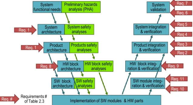
2.4 Fault Injection Requirement of ISO 26262 ... 32
2.4.1 Requirements during Pre-Implementation Phase ... 32
2.4.2 Requirements during Post-Implementation Phase ... 33
2.5 Thesis Orientation & Proposed Methodology Overview ... 36
Chapter 3 Integrating Fault Injection in the Pre-implementation Phase ... 39
3.1 Is Fault Injection Applicable During the Pre-Implementation Phase? ... 40
3.1.1 Preliminaries ... 40
3.1.2 Differences between Pre- and Post-Implementation Phases ... 42
3.2 Application of the FIA Flow at a Given Architectural Level ... 43
3.2.1 Applying FIA at the Product Level L1 ... 43
3.2.2 Relationship between FIA and other Safety Analyses ... 46
3.3 Links between FIA Levels ... 47
3.3.1 S- and Z-shaped Causal Chain... 47
3.3.2 Initialization and Termination of the FIA Flow ... 50
3.4 Steering Column Locking System ... 50
3.4.1 System Description ... 50
3.4.2 Steering Column Locking System FIA (L0) ... 51
3.4.3 ESCL Product FIA Flow (L1) ... 52
3.5 Synthesis on Fault Injection Analyses ... 54
Chapter 4 Fault Injection During Post-implementation Phase ... 57
4.1 FIE Overview ... 58
4.2 From FIA to FIE: Definition of the Experiments ... 59
4.2.2 Experiment Traceability ... 63
4.2.3 Determination of the FIE using FMECA ... 63
4.2.4 Conclusion on the Identification of the Experiments ... 67
4.3 Execution of the Experiments and Evaluation of the Measures ... 67
4.3.1 Optimization of the Experiments ... 67
4.3.2 Assessment of the FIA with regards to the FIE ... 69
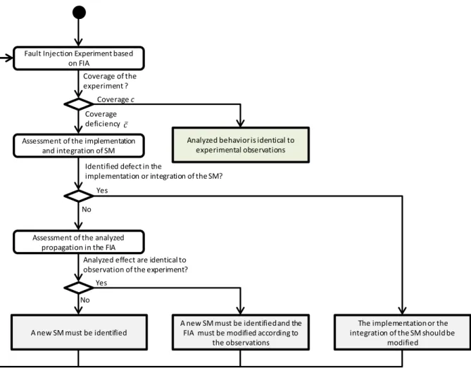
4.3.3 Assessment of one Fault Injection Experiment ... 69
4.3.4 Synthesis of the FIE ... 70
4.4 Conclusion ... 71
Chapter 5 Case Study: Front-Light Manager ... 73
5.1 Application of FIA on the Front-Light Manager System ... 74
5.2 FIA at System Level: Front-Light System ... 75
5.3 FIA at Product Level: Front-Light-ECU ... 77
5.3.1 Safety Analysis of the Micro-Controller ... 78
5.3.2 Freedom From Interferences Analysis ... 78
5.4 FIA at SW Block Architectural Level ... 80
5.4.1 AUTomotive Open System Architecture – AUTOSAR ... 80
5.4.2 Partitioning Concept in AUTOSAR ... 81
5.4.3 Software Architecture of the Front-Light Manager ... 82
5.4.4 Behavioral Description of the Application ... 83
5.4.5 FIA of the Software Architecture ... 84
5.5 S-Shaped Causal Chain ... 86
5.6 SW Module Level: AUTOSAR Watchdog Manager ... 89
5.6.1 Alive Supervision ... 89
5.6.2 Deadline Monitoring ... 90
5.6.3 Control Flow Monitoring ... 90
5.7 FIA at SW Module Level ... 91
5.8 Lessons Learnt ... 93
Chapter 6 Fault Injection Experiments ... 95
6.1 Fault Injection Platform ... 96
6.1.1 Fault Injection Environment ... 96
6.1.2 Fault Injection Characterization of the Tool ... 97
6.2 WdgM Implementations Assessment ... 98
6.2.2 Timing Evaluation of the WdgM... 99
6.2.3 Robustness of the implementation of the WdgM ... 100
6.3 Front-Light Software Verification ... 103
6.3.1 Verification of one Line of FMECA: S-Shaped Verification ... 103
6.3.2 Global Verification of the FMECA Spreadsheet ... 104
6.4 Conclusion ... 105 Conclusion/Perspectives ... 107 APPENDIX 1 ... 111 APPENDIX 2 ... 115 APPENDIX 3 ... 117 Publications ... 119 References ... 121
Figure 1.1 The Ten Parts of the ISO 26262 (ISO 26262, 2011) ... 7
Figure 1.2 Recursive Chain of Dependability Threats ... 10
Figure 1.3 Diagnostic Test Interval, Reaction Time and Tolerance Time Interval ... 16
Figure 1.4 A Typical Fault Injection Environment (Hsueh, Tsai, & Iyer, 1997) ... 17
Figure 1.5 Fault Injection Techniques Classification ... 18
Figure 2.1 Architectural Abstraction Levels of a Vehicle ... 24
Figure 2.2 V-cycle Development Process and Terminology Used ... 26
Figure 2.3 Fault Injection Requirements of ISO 26262 within the Development Process ... 32
Figure 3.1 V-cycle Development Process Phase Addressed in Chapter 3 ... 40
Figure 3.2 FIA Flow of the Product Level and its Interactions with other Activities ... 44
Figure 3.3 Results from the FIA Flow ... 45
Figure 3.4 Iteration of FIA Flow after the Modification of the Architecture ... 47
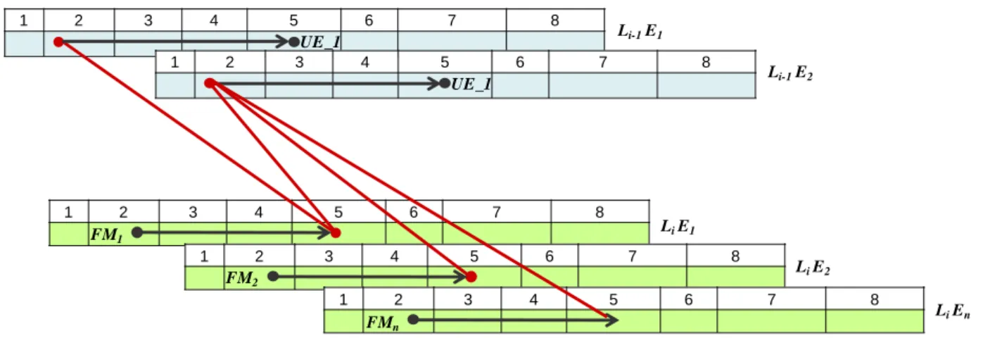
Figure 3.5 S-shaped Causal Chain ... 48
Figure 3.6 Multiple S-shaped Causal Chains from an Initial Failure Mode ... 48
Figure 3.7 Z-shaped Causal Chain ... 49
Figure 3.8 Multiple Z-shaped Causal Chain from an Initial Potential Cause ... 49
Figure 3.9 Steering Column Locking System Architecture ... 51
Figure 3.10 HW and SW Blocks at ESCL Product Level ... 53
Figure 3.11 S- and Z-Shaped Causal Chains in FTA and a FMECA Table ... 55
Figure 4.1 Contributions of Chapter 4 ... 58
Figure 4.2 Illustration of First Strategy ... 60
Figure 4.3 Illustration of Second Strategy for the Definition of Fault Model ... 60
Figure 4.4 Behavioral Description of the Locking Sequence of Motor at Product Level ... 65
Figure 4.5 S-Shaped Causal Chain in the Definition of Global Measures ... 66
Figure 4.7 Product level FIE Flow ... 71
Figure 5.1 Architecture of the Front-Light System ... 74
Figure 5.2 Architecture of the Front-Light ECU ... 77
Figure 5.3 SPC56EL70 Architecture (STMicroelectronic, 2013) ... 78
Figure 5.4 Description of AUTOSAR Layers and Stacks of the Basic Software (AUTOSAR, 2015) ... 80
Figure 5.5 Front-Light Software Architecture ... 82
Figure 5.6 Software Architecture of the Front-Light Manager with the critical path in red of the SW-FMECA line ... 88
Figure 5.7 AUTOSAR WdgM: Control Flow Monitoring Example ... 90
Figure 5.8 WdgM Functional Description ... 91
Figure 5.9 Partial FTA of “No request of the Immediate MCU Reset” Failure Mode ... 92
Figure 6.1 Fault Injection Environment ... 96
Figure 6.2 Effectiveness of EDC/ERC of the two WdgM implementations (104 Experiments) ... 99
Figure 6.3 Robustness Campaign on the WdgM implementations (217 Experiments) ... 102
Figure 6.4 Verification of One FMECA Line (18 Experiments) ... 103
Figure 6.5 Global result of the violation of the Safety Requirements and the Triggered Safety Mechanisms (218 Experiments) ... 104
Table 1.1 Definition of the Safety-ASIL Matrix (ISO 26262, 2011) ... 9
Table 1.2 Safety Analyses Methods ... 12
Table 2.1 Typical Qualitative FMECA Spreadsheet Line ... 29
Table 2.2 Example of Enriched FMECA Spreadsheet with Quantitative data ... 31
Table 2.3 ISO 26262 Requirements for Fault Injection Techniques ... 33
Table 2.4 Interpretation of ISO 26262 Requirements for Fault Injection Techniques ... 35
Table 3.1 Typical Qualitative FMECA Spreadsheet Line (ECSS-Q-30-02B, 2008) ... 46
Table 3.2 Representative FMECA Spreadsheet ... 47
Table 3.3 Functional Requirements of the Products ... 51
Table 3.4 Failure Modes of ESCL ... 52
Table 3.5 Partial FMECA of the Steering Column Locking System: ESCL Product ... 53
Table 3.6 Partial FMECA of the ESCL (Failure Mode of the Micro-Controller Block) ... 54
Table 4.1 Readouts Analysis ... 62
Table 4.2 Considered Line of ESCL Product FMECA ... 64
Table 4.3 System FMECA Leading to Violate Safety Goal 1 ... 67
Table 5.1 Front-Light System’s UEs ASIL Allocation ... 75
Table 5.2 Description of the Functions of the Front Light System. ... 75
Table 5.3 FMECA of the Front-Light System ... 76
Table 5.4 Software Block Undesired Events... 80
Table 5.5 Software FMECA of the Front-Light Manager Module (Subset of the FMECA) ... 85
Table 5.6 Illustration of the S-Shaped Causal Chain ... 87
Table 6.1 Result of Timing Characterization of the WdgM ... 100
Table 6.2 AUTOSAR Specification of WdgM_GlobalStatusType (AUTOSAR-WDGM, 2014) ... 101
ABS Anti-lock Braking System
ADAS Advanced Driver Assistance Systems
API Application Programming Interface
ASIL Automotive Safety Integrity Level
AUTOSAR Automotive Open System Architecture
BSW Basic Software
CAN Controller Area Network
CCF Common Cause Failures
COTS Component Off-The-Shelf
CPU Central Processing Unit
CRC Cyclic Redundancy Check
DAL Design Assurance Level
DC Diagnostic Coverage
DFA Dependent Failure Analysis
DIO Digital Input Output
DTI Diagnosis Time Interval
E/E Electric/Electronic
EASIS Electronic Architecture System Engineering for Integrated Safety Systems
ECU Electronic Control Unit
EDC Error Detection Coverage
EPS Electronic Power Steering
ERC Error Recovery Coverage
ESCL Electronic Steering Column Lock
ESP Electronic Stability Program
FFI Freedom From Interferences
FI Fault Injection
FIA Fault Injection Analysis
FIE Fault Injection Experiment
FMEA Failure Mode Effects Analysis
FMECA Failure Mode Effects and Criticality Analysis
FMEDA Fault Mode and Effect Diagnosis Analysis
FMF Fault Management Framework
FTA Fault Tree Analysis
HiL Hardware in the Loop
HMI Human-Machine Interface
HW Hardware
I/O Input/Output
LFM Latent Fault Metric
LIN Local Interconnect Network
MCU Micro Controller Unit
MiL Model in-the-Loop
MMU Memory Management Unit
MPU Memory Protection Unit
N/A Not available or Not applicable
NA Not Applicable
OEM Original Equipment Manufacturer
OS Operating System
OSEK, OSEK/VDX
Offene Système und deren Schnittstellen für die Elektronik im Kraftfahrzeug, “Open Systems and the Corresponding Interfaces for Automotive Electronics”
PHA Preliminary Hazard Analysis
PiL Processor in-the-Loop
PMHF Probabilistic Metric of Hardware Fault
QM Quality Management
RAM Random Access Memory
ROM Read-Only Memory
RT Reaction Time
RTE Run Time Environment
RTOS Real-Time Operating System
SEU Single Event Upset
SG Safety Goal
SiL Software in-the-Loop
SM Safety Mechanism
SPFM Single Point Fault Metric
SW Software
SW-C Software Component
SWIFI Software-Implemented Fault Injection
TTI Tolerance Time Interval
UE Undesired Event
Introduction
The criticality of automotive embedded systems is becoming a major issue. Indeed, the growing com-plexity of these systems due to the integration of more functionalities as well as the integration of mixed criticality functionalities into electronic systems, may lead to hazardous behavior if the devel-opment process is not improved. The introduction of comfort system (e.g., Electronic Power Steer-ing—EPS), active safety systems (e.g., airbags, brake assist) and, in a near future, of autonomous cars necessitates more stringent verification and validation methods.
Safety is a major issue in the automotive domain, due to the cost of vehicle recall when a critical de-fect is discovered. Major car manufacturers have been confronted to these massive recalls (Shepardson, 2015) (Strong, 2015). In addition, several class actions sued car manufacturers (BARR Group, 2014) (Koopman P. , 2014) for defect of electric/electronic devices. Hence, activities must tend toward a rigorous development process, which closely integrates safety design activities (e.g., definition of safety requirements, definition of safety mechanisms) and the verification activities. The introduction of ISO 26262 standard for functional safety, in 2011, in the automotive industry, is an important step in this direction. The ISO 26262 standard proposes methods and techniques that should be integrated in the development process in order to ensure safety. ISO 26262 notably high-lights that fault injection should be used in the development process. All the verification and validation activities are impacted, even for the verification of the design. This recommendation raised the issue of the role of fault injection in the design phase, which is, as far as we know, a difficult problem that has not been investigated yet.
Fault Injection is a verification technique that has been investigated for a long time (end of the 80’s - early 90’s). Today, fault injection has been applied to many different targets: Operating System – OS, Middleware, web services, web servers, embedded systems, etc. The results of fault injection cam-paigns are twofold: the verification of the fault tolerance mechanisms, with the estimation of error detection and error recovery coverage, and the experimental evaluation of the robustness of the target, i.e. the identification of the failure modes.
In this dissertation, we investigate a fault injection continuum, from system design validation to exper-iments on implemented targets. The proposed approach considers the safety analyses as a starting point, with the identification of safety mechanisms and safety requirements, and goes down to the validation of safety mechanisms implementation with fault injection experiments.
Previous work performed on implemented targets has shown the relevance of the FARM fault injec-tion model. FARM stands for Fault, Activainjec-tion, Readouts and Measures. FARM is a key concept enabling a precise definition of fault injection experiments on implemented targets. Most fault injec-tion studies are based on this model and all studies are compatible with this model.
Our study starts with the investigations of the two following questions: Can the FARM method be applied at the early design phase? What are the expected fault injection’s outcomes in the early validation of safety requirements?
As we will see, these two questions can be refined:
- What are the targets? Can we use the models as targets?
- What are the measures? Is the final aim to check that a safety mechanism exists, or to look for possible violations of a given property?
- What is the fault model? Do we define it from system design, which results in an abstract fault model, or from system semantics, i.e., application-oriented?
- What does activation mean? How behavioral description, defining when fault injection is triggered, can be provided? Should we derive it from use cases, state diagrams or sequence di-agrams?
A deep analysis of these questions led us to develop an approach covering the whole development process, which enables the validation of critical embedded. Our approach shows the link between safety analysis and the application of fault injection in a seamless fashion; it shows the complementa-rities of both approaches in the design and validation process. We show that this approach can be part of the development process of the automotive embedded systems described in the ISO 26262 standard. This dissertation is structured in six chapters.
Chapter 1 and Chapter 2 present definitions and general notions about automotive systems, dependa-bility, and development process.
Chapter 1 discusses dependability notions (dependability attributes, threats and means) and their ap-plicability in the automotive industry, particularly in the context of the ISO 26262 standard. Finally, we focus on a specific verification and validation method: Fault Injection. The state of the art of Fault injection addresses the different objectives of this method, the developed techniques and tools that have been developed and the recent automotive studies related to this topic.
Chapter 2 aims at highlighting the integration of fault injection into the development cycle of an auto-motive system in the context of ISO 26262. We describe separately the activities of the functional development process and the safety development process. Then, we discuss the impacts and the objec-tives of fault injection in the various phases of the development cycle. This discussion raises the main issue of the thesis: the continuous application of fault injection activity all along the development cy-cle of an automotive embedded system.
This question is answered in Chapter 3 and Chapter 4. Our approach enables to manage fault injection in all phases of the development cycle, beginning in the pre-implementation phase (Chapter 3) and ending by the post implementation phase (Chapter 4). The meaning of fault injection during this phase is investigated using FARM model as a framework in all phases. We show the complementarities
be-tween the safety analyses and fault injection. In addition, we show how fault injection experiments should be guided using the results of pre-implementation phases, and we discuss the measures ob-tained in the post-implementation phase on the analyses of the pre-implementation phase.
Chapter 5 and Chapter 6 illustrate the whole methodology on a case study, from analyses to experi-ments. The case study is a Front-Light System, which controls the low-beam headlights of the vehicle. Chapter 5 applies the proposed approach of Chapter 3 and Chapter 4 by performing FIA and identify-ing the fault injection experiments. In Chapter 6, the experiments, defined in Chapter 5, are performed on a prototype using a fault injection tool developed during the thesis.
Finally, we conclude by reminding the main problem addressed, and our principal achievements in dealing with it and recommendations. Possible directions for the future research developments are also presented.
Chapter 1 S
TATE OF THE
A
RT
&
C
ONTEXT
1.1 Electric/Electronic Embedded Systems (E/E Systems) ... 6 1.1.1 Automotive E/E Systems ... 6 1.1.2 Standardization Needs: ISO 26262 ... 6 1.2 Basic Concepts of Dependability & ISO 26262 ... 8 1.2.1 From Dependability Attributes to Automotive Safety Integrity Levels ... 8 1.2.2 From Dependability Threats to Fault Model ... 9 1.2.3 From Dependability Means to Verification ... 11 1.3 Fault Injection for the Verification and Validation of Automotive E/E Systems ... 13 1.3.1 Known Approaches ... 13 1.3.2 FARM ... 14 1.3.3 Techniques ... 17 1.3.4 Related Work in Automotive Systems ... 19 1.4 Conclusion ... 21
In this chapter, our objective is to describe the overall context of this study. We recall here the recent evolution of automotive embedded system, together with standardization of the development process, particularly for safety. Then, we summarize the basic concepts of dependability. These concepts are linked with safety issues and specific terminology of the automotive systems. Finally, the validation technique, i.e., fault injection, is characterized by presenting its approaches, methods and techniques.
1.1 Electric/Electronic Embedded Systems (E/E Systems)
1.1.1 Automotive E/E Systems
Since the end of the 90’s, the automotive industry has changed its way to design vehicles and the un-derlying systems that compose a vehicle. Back then, the systems were designed following a federal architecture where a single ECU was dedicated to one function or service.
The innovation pace has risen quite rapidly, particularly regarding electronic and computing facilities that lead to replace mechanic and hydraulic commands by electronic components. Before that, each function/system of a car was developed independently from the others.
Today’s embedded systems cover a large spectrum of automotive systems: motor control (e.g., fuel injection), passive safety (e.g., airbags), braking systems (e.g., Anti-Lock Blocking System – ABS, Electronic Stability Control - ESP), steering (e.g., Electronic Power Steering - EPS).
These systems exhibit now the following properties:
systems are interconnected. Microcontrollers (or Electronic Control Unit ECU) of the
vehicle communicate with each other.
functions/services are integrated in complex systems. A system provides several
func-tions, e.g., the Body Controller of the vehicle controls windows, lights, immobilizes the vehicle, etc.
functions are distributed on multiple systems. Several parts of a function are hosted by
different systems (microcontrollers). For example, the steering column locking system, or the air conditioning system are distributed.
The main advantage of these solutions is the reduction of the number of ECU in the vehicle. However, it increases significantly the complexity of each ECU. The development efforts are larger and the de-velopment process must be improved in order to ensure a correct behavior of the system, particularly regarding dependability aspects.
1.1.2 Standardization Needs: ISO 26262
The integration of E/E systems raised the problem of the coexistence of functions or services having different levels of criticality in a single system. Indeed, current systems integrate both critical and non-critical functions. A non-critical function can lead to an Undesired Event—UE, i.e., an accident in the worst case. In addition, many actors are involved in the development process of a car: a car manufac-turer (Original Equipment Manufacmanufac-turer – OEM), and several suppliers (Tier 1, Tier 2) which develop products for the system defined by the OEM. Each company has its own development process, there-fore it is necessary to define and follow robust design rules in order to justify work methods and doc-umentation at all development steps. Hence, all activities ensuring dependability have to be traced.
It is worth noting that there are neither regulations nor directives on functional safety in the automo-tive industry. Besides, there is no legal requirement for certification of automoautomo-tive E/E systems. First, several actors decided to adhere (voluntary) to the state of the art defined in the IEC 61508 (IEC 61508, 2010). Contrary to ARP 4754/ED-79 (SAE International, 2010) Guidelines For Development Of Civil Aircraft and Systems, ED-12#/DO-178#(RTCA & EUROCAE, 2011) (with # = A in 1985, B in 1992 and C in 2011) for Software Considerations in Airborne Systems and Equipment Certi-fication, or the safety guides (e.g. 50-SG-D3 and 50-SG-D8) in nuclear industry, this standard is not reserved to only one domain. Indeed, it proposes an approach applicable to generic embedded systems. The IEC 61508 standard focuses on the overall development process of a system and the steps that have to be respected in order to achieve safety. Particularly, it defines achievable goals for the specifi-cation, the design, the implementation and the assessment of Electrical/ Electronic/ Electronic Pro-grammable Systems (E/E/EP).
Since 2011, a derived version called ISO 26262 (ISO 26262, 2011) is used. This standard is the result of a joint work between the major actors of the automotive domain aiming at specifying best practices for the documentation, the interactions between actors and the methods and techniques to justify func-tional safety of systems. This standard facilitates exchanges between OEMs and suppliers by exhibit-ing requirements to achieve.
The scope of the ISO 26262 is the functional safety, i.e., “the absence of unreasonable risk due to hazards caused by malfunctioning behavior of E/E systems”. “Non functional safety” aspects are out of the scope of the study, e.g., a cause of a malfunction could not be a fire caused by external condi-tions, such that a humid environment on an E/E system, or an electrical shock with a contact to a high voltage source. Instead, functional safety covers fire due to an over excitation of an alternator within the system in operation (design bug, aging of wires, etc.).
The ISO 26262 is divided in ten parts as described in Figure 1.1.
FIGURE 1.1THE TEN PARTS OF THE ISO 26262(ISO 26262,2011)
Our work deals with Parts 4, 5 and 6, which provide all the requirements for the development of an automotive system. However, other parts are also very helpful for understanding these requirements: Parts 1, 8, 9 and 10.
1.2 Basic Concepts of Dependability & ISO 26262
The definition of dependability emerged from the work done in the IFIP WG10.4 working group on Dependable Computing and Fault Tolerance: Dependability is defined as the “trustworthiness of a computing system which allows reliance to be justifiably placed on the service to deliver”. (IFIP WG 10.4, 2015)
Dependability is a key concept for any critical system. It could be seen as the aptitude to avoid the failures that occur during service delivery. The service corresponds to behavior perceived by the users (human or not) or services in interaction with it.
Dependability is also a well-documented concept, and a complete taxonomy can be found in (Avizienis, Laprie, Randell, & Landwehr, 2004). Indeed, dependability is defined by six attributes, three threats and four categories of means.
1.2.1 From Dependability Attributes to Automotive Safety Integrity Levels
1.2.1.1 Dependability Attributes
Dependability encompasses the following attributes, which characterize the quality of the delivered service:
Availability: readiness for correct service;
Reliability: continuity of correct service;
Safety: absence of catastrophic consequences on the user(s) and the environment;
Confidentiality: absence of unauthorized disclosure of information;
Integrity: absence of improper system alterations;
Maintainability: ability to undergo modifications and repairs.
Depending on the industrial field, the significance of each attribute varies. This choice relies on the objectives that should be achieved for a given service. For example, in transportation fields, reliability and safety are of prime priority; in communication system, availability, reliability and confidentiality are the target attributes.
Historically, in automotive industry, the effort was on the achievement of reliability and availability. The improvement of the reliability of components was sufficient to improve the quality of service. Then, the growing complexity and the criticality of E/E systems lead to focus on safety. Today, securi-ty importance is rising quickly, in parallel with car’s connectivisecuri-ty. In the following of this work, we will mainly concentrate on safety aspects.
1.2.1.2 Safety & Automotive Safety-Integrity Level
Considering the dependability attributes, the actor of a given domain can define a scale of criticality for the given attribute. Indeed, all systems should be developed correctly! However, depending on their level of criticality, they do not require the same development efforts, in terms of both design and validation. For example, car audio and video systems do not require the same safety effort than a fuel injection system.
The ISO 26262 standard introduces the concept of Automotive Safety Integrity Level (ASIL). They are four levels: from ASIL A (the less critical) to ASIL D (the most critical). There is also a level,
noted Quality Management (QM), which is not associated with any specific requirements. Hence, no safety-related activities are required by ISO 26262 in this case. The ASIL is determined by the highest criticality of hazards, situations at vehicle level that may lead to harm person the system is interacting with.
When assigning these levels, three parameters must be taken into account, see Table 1.1:
1. severity that is based on the seriousness of injuries caused by incidents or accidents (S1: Light and moderate injuries, S2: Severe and life-threatening injuries (survival probable), S3: Life-threatening injuries (survival uncertain), fatal injuries);
2. probability of exposure. Occurrence of the use case: E1: very low probability, E2: Low probability E3: Medium probability, E4: High probability;
3. controllability. It is a subjective concept that is based on the abilities of the “road
us-er” (e.g., drivers, pedestrians, etc.) to handle the hazard (C1: Simply controllable, C2:
Normally controllable, C3: Difficult to control or uncontrollable).
The objective of these criticality levels is to quantify the level of “trust” at which the system should be designed to provide its functions correctly. The more safety critical the system is, the higher the ASIL is, resulting in stringent efforts to comply with the standard.
TABLE 1.1DEFINITION OF THE SAFETY-ASILMATRIX (ISO 26262,2011)
Controllability Severity of the harm Probability of expo-sure C1 C2 C3 S1 E1 QM QM QM E2 QM QM QM E3 QM QM ASIL A E4 QM ASIL A ASIL B S2 E1 QM QM QM E2 QM QM ASIL A E3 QM ASIL A ASIL B E4 ASIL A ASIL B ASIL C
S3
E1 QM QM ASIL A E2 QM ASIL A ASIL B E3 ASIL A ASIL B ASIL C E4 ASIL B ASIL C ASIL D
Due to the imperfections inherent to all systems, dependability attributes have to be interpreted in a relative sense, not in an absolute, deterministic one. The requirements for the attributes are therefore specified according to levels and some of them may not be required for a given system.
1.2.2 From Dependability Threats to Fault Model
1.2.2.1 Dependability Threats
The threats to dependability are faults, errors, failures. A service failure, also abbreviated to failure, is an event that occurs when the service delivered by the implemented system function deviates from the correct service. Hence, it affects the targeted level of satisfaction of one or several dependability attributes. They are linked within the chain of dependability threats illustrated in Figure 1.2.
FIGURE 1.2RECURSIVE CHAIN OF DEPENDABILITY THREATS
At the beginning of a service failure, there is a fault, i.e. the origin of a potential failure. A fault is a defect that can be internal or external to a system. They have been classified into three major overlap-ping categories (Avizienis, Laprie, Randell, & Landwehr, 2004):
development faults, that include all fault classes occurring during development;
physical faults, that include all fault classes that affect hardware;
interaction faults, that include all external faults.
Although a system may contain a fault, its input and state conditions may never cause this fault to be activated so that an error occurs; in this case, the fault is referred as dormant. Then, as soon as a fault has been activated, it produces an error, i.e., a part of the system state that may cause a subsequent service failure. The failure occurs when a propagating error –internal propagation– reaches and alters the interface of the considered system service.
Finally, the failure may propagate to the interface of another system service (external propagation), that appears as an external fault to this service. It is referred to as causation.
1.2.2.2 Fault Model in Automotive Embedded Systems
An automotive embedded system may fail in operation due to either physical faults (hardware aging, EMC, etc.) or residual bugs from design or development phase.
Regarding the faults of systems and specific hardware elements, a classification is proposed in the Annex D of ISO 26262-5 (ISO 26262, 2011). In the table, given in APPENDIX 1, each type of ele-ment is considered: E/E System, relays, communication links, sensors, processing units, etc.
Then, for each component, a set of typical faults, errors or failures of hardware is described. The pro-posed listing “does not claim exhaustiveness and can be adjusted based on additional known faults or depending on the application”. This is intended to provide a representative guideline of the fault mod-el that should be considered in the automotive domain. For example, sensor fault modmod-el encompasses faults such as stuck-out of range, stuck-in range, oscillations and offsets.
This table also proposes a guideline for the diagnostic coverage achievable by a safety mechanism. According to this table, a safety mechanism that covers a category (each component has three catego-ries) of faults has the ability to achieve low (60%), medium (90%) or high (99%) diagnostic coverage. For example, a safety mechanism covering all the sensor faults described previously can pretend to achieve a high, 99% DC. “Input comparison/voting (1oo2, 2oo3 or better redundancy” is a proposed measure to achieve this high DC.
It should be noted that a similar classification of the Appendix D of ISO 26262-5 has been also done in the Electronic Architecture and System engineering for Integrated Safety systems—EASIS Europe-an project (Lu, 2009a). However, EASIS classification does not propose Europe-an achievable DC level.
System B System A
Failure Error
Specifically, in software applications, physical faults are modeled as permanent fault (leading to hang or crash) and transient faults (e.g. bit-flips and stuck-at in the code and data memory segments leading to value errors). Such faults are always possible due to the aggressive environment of automotive ap-plications and the increasing complexity of the hardware components and system architecture.
To take into account such aggressive environments and complex architectures, ISO 26262-6 (highly) recommends injection of arbitrary values (e.g., by corrupting values of variables, by introducing code mutations, or by corrupting values of CPU registers).
Regarding software faults, also called systematic faults, they may occur due to non-respected rules during the design. The errors could be introduced in system, hardware or software design, because of a misinterpretation of the specifications. In software, the following are potential causes of these design errors: wrong temporal design (sizing, execution order, etc.), wrong resource sizing, wrong data usage (wrong choice of data for usage, wrong handling of a data, etc.) or non-expected modes. These bugs are introduced during manual coding, or with compiler or linker’s default.
1.2.3 From Dependability Means to Verification
Finally, dependability means, whose objective is to ensure dependability attributes from dependability threats, are grouped in four categories:
fault prevention aims to prevent the occurrence or introduction of faults;
fault tolerance aims to avoid service failure in the presence of faults;
fault removal aims to reduce the number and the severity of faults;
fault forecasting aims to provide an estimation of the present number of faults, future
incidence and possible consequences of faults.
Fault prevention is ensured by quality control techniques, such as adherence to design rules, through-out the development and the manufacturing process of the system.
1.2.3.1 Fault Tolerance
In order to prevent a service failure, a fault tolerant system needs to integrate in its design error han-dling techniques, including error detection, error correction, error recovery, redundancy and diversi-fication (for systematic faults).
All these techniques, when integrated in a design, provide a fault tolerant architecture against pre-defined faults. Various architectures have been studied and each industrial domain has developed solu-tions that meet its constraints. For example, triplication with majority vote is a common solution for railways, avionic or aerospace systems since decades, contrary to the automotive domain where this robust solution is usually not necessary, and fail-safe designs are used.
1.2.3.2 Fault Forecasting
Fault forecasting is conducted by performing an evaluation of the system behavior with respect to fault occurrence or activation. The evaluation is composed of two aspects:
qualitative, or ordinal, evaluation. This aims at identifying, classifying, ranking the
failure modes, or the event combinations (components failures or environmental condi-tions) which may lead to system failures,
quantitative, or probabilistic, evaluation. This aims at evaluating in terms of probabili-ties the extent to which some of the attributes of dependability are satisfied; those at-tributes are then viewed as measures of dependability. This evaluation is based on the alternation of correct and incorrect service delivery, to define reliability, availability and maintainability measures.
Particularly in the automotive domain, specific metrics have to be calculated: Probabilistic Metric of Hardware Failure (PMHF), Single Point Fault Metric (SPFM) and Latent-Fault Metric (LFM). Numerous methods enable to evaluate qualitative and quantitative aspects. Table 1.2 lists safety analy-sis methods.
TABLE 1.2SAFETY ANALYSES METHODS Safety analysis
method Qualitative Quantitative Automotive Industry Specific Information HA&RA1 Also referred to as Preliminary Hazard
Anal-ysis (PHA) in automotive industry
FME(C)A2
FMEDA3
Specific to automotive industry. Enables the calculation of architectural metrics from the
ISO 26262 (SPFM and LFM)
DFA4 Analyzes independence, and non-interference between elements of the component
CPA
FTA5
RBD6
Markov Chain7
Stochastic Petri Nets
ETA8
Then, the evaluation of the measures can be performed using modeling and analyses but also through testing. This experiment-based approach is tackled with fault injection techniques.
1.2.3.3 Fault Removal
Here, we focus on the fault removal activities during development phase. In this phase, the objective is to perform preventive or corrective maintenance, by patching software, replacement of electronic de-vices, etc.
The fault removal activity consists mainly in a verification process, which leads to diagnose the threats and finally to proceed to the necessary corrections. Then, the process must be repeated in order to check that the fault removal process has not inserted new faults. In practice, this step is referred to as non-regression verifications.
1 Hazard Analysis & Risk Assessment (e.g., HAZOP) (M2OS, 2014)
2 Failure Mode, Effect (and Criticality) Analysis (Bouti & Kadi, 1994), (Department of the Army, 2006), (ECSS-Q-30-02B,
2008)
3 Failure Mode, Effect and Diagnosis Analysis (L'Hostis, 2013) 4 Dependant Failure Analysis (ISO 26262, 2011)
5 Fault Tree Analysis (Barlow & Lambert, 1975)
6 Reliability Block Diagram (SaRS: Safety and Reliability Society, 2011) 7 (SaRS: Safety and Reliability Society, 2011)
Verification techniques can be classified according to whether or not they involve exercising the sys-tem. One the one hand, if the system is not activated these are called static verification techniques. Static analyses can be performed manually or automatically. Manual ones are “inspections”, “re-views”, “walkthrough” techniques (Aurum, Petersson, & Wohlin, 2002), consisting in a detailed anal-ysis of a system artifact (specifications, design, source code, etc.). Even if this technique is time con-suming, a large number of faults can be identified prior to any execution of the system. Automatic ones based on software tools give informative metrics or lists of anomalies. Static analyses also in-clude theorem proving (requires formal specifications in this case) and model-checking techniques. On the other hand, the dynamic verification techniques of the system are usually referred to as
test-ing. A test aims at providing inputs to a system, and verifying that the observed behavior is correct
with respect to the specifications. Due to complexity of modern automotive systems, it is not manage-able to verify exhaustively a system (except for very specific simple cases). Indeed, a test campaign does not provide a proof of the zero-default behavior of the system; nevertheless, it enables to increase designers and developers’ trust in the system quality.
Moreover, a test is driven by verification objectives: performance, functional requirement, robustness,
etc. Each of the test categories is important and provides complementary information on the systems.
Among testing objectives, the introduction of dependability raises the issue of the verification of fault tolerance mechanisms. Similarly to other verification techniques mentioned before, it is mandatory to introduce faults or errors in the system to validate the fault tolerance mechanism during the testing phase. This technique called fault injection (FI) will be discussed in the following section.
1.3 Fault Injection for the Verification and Validation of Automotive
E/E Systems
The introduction of fault injection in ISO 26262, in 2011, has renewed the interest of this method in the automotive industry. However, this well-established verification method is now used by many industries in several domains. Fault injection (Barbosa, Karlsson, Madeira, & Vieira, 2012) is a key technique in the evaluation of the dependability of systems. We have seen in the previous section that fault injection was a dedicated method for both fault forecasting, by predicting the post-deployment behavior of the systems under real threats and fault removal, by identifying weaknesses or defects in the implementation of safety mechanisms.
In this section, we first identify the objectives of fault injection campaigns, and show how to charac-terize a fault injection environment, particularly the attributes of fault injection. We also give an over-view of typical fault injection techniques and tools, and finally several studies related to the automo-tive domain are discussed.
1.3.1 Known Approaches
The insertion of faults into systems during the verification phase has been recognized useful in many works to enhance the quality of service regarding fault handling, and thus to improve the dependability of a system. The first approach is based on the idea that the environment of the target is corrupted. Hence, the goal is to evaluate the ability of the system to handle unexpected inputs, caused by a fault in the environment of the system under test. This approach has been investigated in RIFLE (Madeira, Rela, Moreira, & Silva, 1994), BALLISTA project (Koopman, DeVale, & DeVale, 2008).
A second approach consists in performing a modification of the target by inserting an artificial fault and observing the behavior of the reaction of the target. The objective of the latter is the validation of the internal fault tolerance mechanisms or/and the evaluation of the failure modes distribution (Albinet, Arlat, & Fabre, 2004).
Both approaches can be applied to perform robustness testing and dependability benchmarking (DBench, 2004). A framework for defining dependability benchmarks for computer systems was de-veloped in the DBench European project. This framework emphasizes the validation of Commercial-Of-The Shelf (COTS) components, in particular operating systems (e.g. several Linux and Windows versions).
Finally, another fault injection approach evaluates the ability of the tests cases to detect faults: Muta-tion testing (DeMillo, Guindi, McCracken, Offutt, & King, 1988). This well-known technique allows the improvement of software quality during the development. In this approach, bugs are introduced in a program: manually – hand-seeded faults –, or automatically generated (mutants) using rules intro-ducing defects. In the following, we will concentrate on safety related, deterministic testing, hence this last fault injection technique will not be developed.
1.3.2 FARM
Several studies have proposed a structure for fault injection environments. To set up a fault injection campaign (Christmansson & Chillarege, 1996), several questions need to be addressed:
1. What is the appropriate error model that mimics representative software faults? 2. Where should the error be injected to emulate a particular software fault? 3. When should the error be injected?
4. How should a representative operational profile (i.e. a probabilistic description of sys-tem usage) be designed that will maintain reasonable experiment times?
5. What readouts should be collected, and which measures should be calculated?
6. How should the calculated measures be related to analytical models of dependability? Among the various fault injection environment models based on the above key issues, one has been particularly used in different works to characterize fault injection on a Target: the FARM model (Arlat, et al., 1990), (Arlat, Costes, Crouzet, Laprie, & Powell, 1993), (Benso A., 2011). The FARM model is composed of the four following attributes:
the set of faults to be injected (the Fault model),
the system activities under which the faults are injected (the Activation),
the Readouts of the experiment results,
and the Measures evaluated, based on data of the experiments < F, A, R >.
The FARM model characterizes in an effective way the fault injection environment, and it is used in this study as a reference for the definition of fault injection experiments.
1.3.2.1 Fault Model
The set of faults to be injected into the target is also called a fault list. Each fault is characterized by a model (e.g. stuck-at, bit-flip, etc.), a location (e.g. memory address, a pin, etc.) and an injection time (e.g. event-driven, after a given time, etc.).
Generally, the size of the fault list is assumed to be infinite. An exhaustive set of experiments covering the full fault list in fault injection campaign is impossible to achieve. In practice, the fault list used to perform the experiments is a subset of the entire fault list that can be injected in a reasonable time but still able to provide significant results: the main criteria here is the representativeness of the fault model. Many studies have dealt with this problem (Natella R. , 2011) (Costa, Silva, & Madeira, 2009) (Natella, Cotroneo, Duraes, & Madeira, 2013).
Orthogonal Defect Classification (ODC) (Christmansson & Chillarege, 1996) is a measurement tech-nology that is consistently applied to a large number of IBM projects. The fault types, representing the defects in the source code, are classified in six types, as follows: Assignment, Checking, Algorithm, Timing/Serialization, Interface, and Function.
1.3.2.2 Activation Model
The set of activations A specifies how the target is exercised (its functional behavior) during the ex-periment. It corresponds to a set of functional inputs applied to the target. The complexity of the Acti-vation model directly influences the length of an experiment, as the injection time is directly depend-ent of the Activation length. This Activation model is often referred as the Workload of the fault injec-tion campaign. An important characteristic of the workload is again its representativeness; ideally, it should be similar to the real behavior of the system in operation. However, most of activation models are implemented with synthetic workload, not representative of the real behavior, but easy to handle and to observe (readouts). An incorrect activation model A may result in the two main consequences:
i) incomplete or non-significant results — the inferred measures obtained on the target are biased; or
ii) no effect of the faults is perceived — when the fault is not activated by the workload. In this case,
the experiment is categorized as harmless whereas it could lead to a critical failure using a different activation set. The Activation model could be defined based on operational profiles to be representa-tive of the activation of the target or scenario-based test from the use cases defined during system def-inition.
1.3.2.3 Readouts Model
The set of Readouts corresponds to the logged behavior of the system, data and events, execution flow, etc. It encompasses all the observations that can be made on the target system. This is strongly dependent on the target system and the fault injection tools. A simulated execution of a system is easi-er to monitor than a prototype. Howeveasi-er, the choice of R must be done carefully since it has a strong impact on the results and the analysis. The set of readouts R is composed of variables values, states of the system, detection timing, etc.
1.3.2.4 Measures Model
The Measures are obtained from the Readouts during or after an experiment. Different types of Measures can be assessed. First, the behavior of the target system in the presence of faults can be evaluated, particularly the failure mode distribution. A severity scale called CRASH has been defined in BALLISTA project (Koopman, DeVale, & DeVale, 2008) to characterize the behavior of Operating System and middleware. CRASH is an acronym for: Catastrophic, Restart, Abort, Silent, Hindering. In BALLISTA, a fault corresponds to the corruption of the parameters of a system call executed by a process. The semantics of these failure modes is thus the following:
- Catastrophic: the target computer crashes;
- Abort: the benchmark process aborts (e.g. core dump); - Silent: no error code is returned when one should have been; - Hindering: an incorrect error code is generated
It is worth noting a specific scale must be defined for a given target, although some similarities can be found with other existing scales. The definition of these categories is a major issue. Moreover, the measure should not only tackle the first occurrence of a failure mode but also next ones. The work presented in (Albinet, Arlat, & Fabre, 2004) has shown that the first occurrence of a failure is not al-ways sufficient to characterize a fault injection experiment. The detection of the error may occur and in that case, the system is restarted. However, the restart can be insufficient, as another catastrophic failure may occur. Hence, the verification that a reaction has been performed is not sufficient to char-acterize if the system is safe, and the target should be observed for a second failure.
The main measures concern error detection coverage (EDC) and error recovery coverage (ERC). Most of the time these measures are illustrated with pie diagrams distinguishing an error detection sector and another sector giving the distribution of failure modes when the error is not detected. EDC is computed according to Equation 1.1.
Equation 1.1
Another important set of measures is the determination of error handling timings, and the Error han-dling timings of the fault tolerance mechanisms.
The timing requirements of fault tolerance are defined in the ISO 26262 part 1 (ISO 26262, 2011), and Figure 1.3 illustrates the associated terminology.
FIGURE 1.3DIAGNOSTIC TEST INTERVAL,REACTION TIME AND TOLERANCE TIME INTERVAL
First, before the occurrence of the fault, the whole system is in a fault free state or normal operation. Then, when the fault is activated, the system enters in an abnormal system state, in which the error detection mechanisms should handle the error. The error can also remain latent or lead to a failure when there is propagation of the error. When the error is detected, a recovery procedure is needed to handle the error and put the system in a fail-safe state or trigger a degraded mode of operation. The Diagnostic Test Interval (DTI) is the upper bound of the interval between the occurrence of the fault and the detection, this time is defined according to the period of the recurrent test use to detect the error. The Reaction Time (RT) is the time between the detection and the end of the recovery.
Finally, a Tolerance Time Interval (TTI) is the delay between the fault activation and the violation of a safety goal. The Tolerance Time Interval is an intrinsic characteristic of a system. It should be noted
Normal
Operation Latent Error Failure Safe Mode
Error Propagation
Error tolerated Reaction time
Diagnostic Test Interval Fault
Activation
Error Detection
Tolerance Time Interval Fault
Activation
Normal
Operation Latent Error Failure
Unsafe Mode
Violation of a Safety Goal
that the transition to a failure mode may not be sufficient, as a failure mode could be tolerated a short amount of time. For example, the loss of the headlights while driving on a motorway is a failure, how-ever, it is considered “safe” if the failure is tolerated within 500 ms.
The TTI is difficult to estimate in practice. However, the following relation must be ensured:
Equation 1.2
To conclude, it is worth to mention that the Measures to be evaluated have to be defined first, since they guide the whole fault injection process. However, their values are evaluated in the last step, by processing information given by the Readouts. The Fault model, the system Activation and the
Readouts have to be defined to obtain the significant Measures in an efficient way.
1.3.3 Techniques
Several Fault injection techniques have been applied to different types of targets (hardware, software, simulation models, etc.). While these techniques are very different in their implementation, they all share the same environment described in the following section. Then, a section is dedicated to an overview the existing fault injection techniques and tools.
1.3.3.1 Environment
A fault injection environment (Hsueh, Tsai, & Iyer, 1997) of a Target System should encompass the following components, as defined in Figure 1.4:
The Target System.
The Controller controls the whole experiment, i.e., the Workload Generator, the
Fault Injector and the Monitor.
The Fault Injector injects faults selected from the Fault Library into the target system.
The Workload Generator generates the inputs, selected from the Workload Library,
for the target system.
The Monitor tracks the execution of the fault injection experiment for the Controller
and the Data Collector
The Data Collector collects the data (Readouts) during the experiment.
The Data Analyzer analyzes the Readouts collected by the Data Collector
FIGURE 1.4ATYPICAL FAULT INJECTION ENVIRONMENT (HSUEH,TSAI,&IYER,1997) Fault Injection System
Target System Monitor Fault Injector Workload Generator Data Analyzer Data Collector Controller Fault library Workload library
1.3.3.2 Techniques and Tools
Fault injection is a mature technology that has been successfully applied using several techniques on different targets. It is important to notice that the number and the diversity of fault injection techniques is a consequence of the type of targets that have been investigated (hardware, software, models). Many techniques are based on specific tools, often developed for a different purpose (e.g. debugging), to perform fault injection. These tools allow either to inject a specific fault model or to control a specific target.
Fault injection techniques can be categorized depending on the target type (Hsueh, Tsai, & Iyer, 1997), (Ziade, Ayoubi, & Velazco, 2004), (Svenningsson R. , 2011). The classification is illustrated in Figure 1.5.
FIGURE 1.5FAULT INJECTION TECHNIQUES CLASSIFICATION
Physical fault injection can be performed by bombarding the system with either heavy-ions (Karlsson, et al., 1998) or electromagnetic interferences (EMI) (Karlsson, Liden, Dahlgren, Johansson, & Gunneflo, 1994), to mimic Single Event Upset (SEU) that could happen in operation. Today, this technique is less applied as the major drawbacks are the low controllability, and the lack of repeatabil-ity of experiments with this method.
Then physical fault injection is divided into two parts:
i) Injection of faults in the hardware of the system (e.g. stuck-at faults), i.e. Hardware
Implemented Fault Injection— HIFI, and
ii) Simulation of physical faults in the software of a system, i.e. Software Implemented
Fault Injection—SWIFI.
Typically, HIFI corresponds to pin-level fault injection and test-port based fault injection. Pin-level fault injection encompassed techniques that emulate faults by affecting the state of pins of an integrat-ed circuit (Madeira, Rela, Moreira, & Silva, 1994) (Arlat, et al., 1990). Test-port basintegrat-ed fault injection techniques rely on debug ports available on several microcontrollers and CPU in order to access the memory of a chip and simulating the effects of hardware faults. One variant of this technique is based on the Nexus standard or IEEE-ISTO 5001-2003 (Nexus5001) (Dees, 2012) that defines a standard debugging interface. This technique has been used in GOOFI (Aidemark, Vinter, Folkesson, & Karlsson, 2001) (Skarin, Barbosa, & Karlsson, 2010) and INERTE (Yuste, de Andrès, Lemus, Serrano, & Gil, 2003). This standard is indeed integrated in the microcontrollers used in the automo-tive industry.