O
pen
A
rchive
T
OULOUSE
A
rchive
O
uverte (
OATAO
)
OATAO is an open access repository that collects the work of Toulouse researchers and
makes it freely available over the web where possible.
This is an author-deposited version published in :
http://oatao.univ-toulouse.fr/
Eprints ID : 18844
The contribution was presented at ISD 2016:
http://www.isd2016.ue.katowice.pl/
To cite this version :
Valente, Pedro and Rocha Silva, Thiago and Winckler,
Marco Antonio and Nuno, Nunes The Goals Approach: Agile Enterprise
Driven Software Development. (2016) In: 25th International Conference on
Information Systems Development (ISD 2016), 24 August 2016 - 26 August
2016 (Katowice, Poland).
Any correspondence concerning this service should be sent to the repository
administrator:
[email protected]
P. Valente (*)
University of Madeira, Funchal, Portugal e-mail: [email protected]
T. Silva
Université Paul Sabatier, Toulouse, France e-mail: [email protected]
M. Winckler
Université Paul Sabatier, Toulouse, France e-mail: [email protected]
N. Nunes
Madeira Interactive Technologies Institute, Funchal, Portugal e-mail: [email protected]
The Goals Approach: Agile Enterprise Driven
Software Development
Pedro Valente, Thiago Silva, Marco Winckler and Nuno Nunes
Abstract. Continuous Business Process Improvement (BPI) is necessary in order to maintain and develop the enterprise competitiveness. However, achieving a level of software development performance that matches enterprise needs in terms of pro-ducing noticeable results within small amounts of time is a persnickety task, mainly because most available methods do not deliver full software architectures that can be directly used for in-house software development without iterations between imple-mentation and design, as produced specifications are too close to the user interface, or too close to business regulations and domain modeling. Our approach applies a method that structures business processes, business rules and domain concepts, and uses this information in order to identify user tasks (use cases) and interaction spaces, and by means of their detail, methodically specify the software architecture for a particular BPI, bridging business and software using cross-consistent concepts. We present a theoretical example, and the validation of our method.
Keywords: Enterprise Engineering · Software Engineering · Human-Computer In-teraction · Enterprise Architecture · Software Architecture
1
Introduction
Software development within enterprises still lacks accuracy, and effectiveness is still far from being achieved as project full-success rates are still as low as 30% [1], and there is still a long bridge to cross until software development within enterprises is achieved in a patterned way, and established as a consistent source of revenue following investment within enterprises [2]. Nevertheless, the advances of Software Engineering (SE) have at least taken us from a chaotic state of the practice [3], to a more inspiring situation where enhanced executive management support, agile meth-ods, and increased user involvement are appointed as factors for software project success [4].
Our work is inspired by the need to improve software project success rates within enterprises, where the establishment of a tool that enhances communication capabil-ities between both Enterprise Engineering (EE) and Software Engineering (SE) knowledge-based expertise can be seen as crucial for the effectiveness of the Soft-ware Development Process (SDP) that may be applied. However, this enhancement can only be achieved if a common framework of shared concepts of the business and software domains is established and used to build the Information System, which today can be seen an inherent part of the global enterprise system.
We present the Goals Approach, which focuses on tailored in-house development of Information Systems for Small and Medium Enterprises, which is characterized by needs of agility concerning the supportive SDP in order to allow the achievement of tangible results in limited amounts of time and budget [5]. Goals defines a SDP that applies a straightforward method that analyses the enterprise in a top-down pro-cess in order to elaborate a business model, called as Enterprise Structure. And tinues by detailing the Enterprise Structure components using cross-consistent con-cepts in order to design the User Interface, the Business Logic and the Database, including the Enterprise Structure as the back-bone of a final Software Architecture, which can be used for in-house software development management.
Briefly, the Goals conceptual structure (back-bone Enterprise Structure compo-nents are underlined) includes: the human interaction which is represented by means of Business Processes, User Tasks, User Intentions and User Interactions; the User Interface which is represented by Aggregation Spaces, Interaction Components, In-teraction Objects, and InIn-teraction Spaces; which (the last one) can also be used by its Business Logic, which is composed by Business Rules, User Interface and Database System Responsibilities; and the Database which is composed by Data Entities and Fields.
This paper focuses on the validation of the cross-consistency of concepts that sup-ports each component, and provides insight on how each can be implemented. The related work to our approach is presented in Section 2, the Goals Approach SDP and Structure are presented in Section 3. The method is presented in Sections 4 (Analysis Phase) and 5 (Design Phase), the cross-consistency validation is presented in Section 6, and the conclusions and future work are presented in Sections 7 and 8.
2
Related Work
Considering enterprise-driven development in the EE domain, our approach is dis-tinct from the DEMO-based GSDP [6] as it provides a structured user interface spec-ification. e3Value [7], is a method which also relies on the GSDP, and models the business for value adding the “value interface” inputs and outputs, yet, also not providing a user interface elaboration solution. Still in EE, our approach can be com-pared to Archimate [8] and BPMN [9] in the perspective that it provides an enterprise and software structuring language. It is however different in the perspective that it applies a method to specify a business model and derive a software architecture.
Our approach can be compared to the business-oriented ‘Management by projects’ [10], ITIL [11], and the SE’ SCRUM [12] and XP [13] methods, which also define techniques and architecture for BPI, yet, none of these methods specifies the software architectural pattern that should be used. Goals can be used by these methods for software architectural specification, and in the cases of SCRUM and XP for the spec-ification of architectural spikes regarding iterative implementation, matching agile software architecture [14], as Goals further structures the enterprise business model. Regarding the Human-Computer Interaction perspective, the closest solutions are methods that settle for user interface conception based on user task and domain mod-els [15, 16]. Our approach is different as it complementarily conceives the Business Logic layer based on enterprise business regulations and coordination structures.
3
Software Development Process
Goals is an Enterprise-Driven Human-Centered Software Engineering (HCSE) method that bridges enterprise requirements and software implementation by means of a business model. It introduces the Interaction Space as the space that supports both in-person and remote interaction whilst applying the same business regulations and data concepts. The Interaction Space bridges the Business Processes and its User Task’s human interaction, and establishes a relation with the Business Rule and Data Entity concepts in order to architect the Enterprise Structure (the business model) which is the back-bone of Software Architecture.
Goals was developed for over a decade of applying the HCSE Wisdom Approach [17] in software practice in a SME. Wisdom provides the (original) definition of In-teraction Space (IS) and the architectural technique that bridges human inIn-teraction and system behavior (based on the IS), expressed by User Tasks and Business Rules in the Enterprise Structure, and by User Interactions and System Responsibilities in the Software Architecture. It uses DEMO [18], for the definition of Business Process and Business Rule, Activity Modeling (AM) [19], for the cornerstone definition of User Task. And uses Hydra [20], for the User Interface definition of Aggregation Space, and BDD [21] for system behavior specification, both concerning the Soft-ware Architecture elaboration.
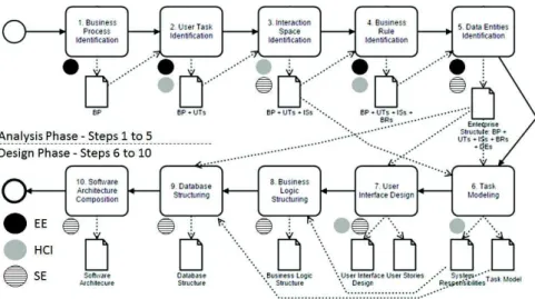
The Goals Approach Software Development Process (SDP) integrates the Enterprise Engineering (EE) and Human-Computer Interaction (HCI) perspectives in the pro-cess of defining a Software Architecture for a given Business Propro-cess Improvement (BPI) in two phases: the Analysis Phase which elaborates the Enterprise Structure, and the Design Phase which elaborates the Software Architecture.
The Analysis Phase identifies Business Processes (BP) in Step 1, User Tasks (UT), in Step 2, Interactions Spaces (IS) in Step 3, Business Rules (BR) in Step 4, and Data Entities (DE) in Step 5, composing the Enterprise Structure. The Design Phase details and complements the Enterprise Structure by means of a User-Centered Design (UCD) perspective, specifying each UT by means of a Task Model (Step 6), designs the User Interface (Step 7), and structures the Business Logic (Step 8) and the Data-base (Step 9), finishing with the elaboration of a final Software Architecture (Step 10), given an MVC architectural pattern [22].
The process continues with the Implementation and Testing Phases (which detail is out of the scope of the present paper), and uses the Software Architecture to guide the software development, and the User Interface Design, Task Model and User Sto-ries to guide the Information System test before deployment. Figure 1 illustrates the SDP Analysis and Design Phases using a BPMN diagram [9], and each EE, HCI and SE domain’s contribution and cooperation suggestions for each Step.
Fig. 1. Goals Software Development Process.
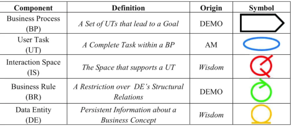
The Enterprise Structure is the Goals business model, and is composed of Business Processes (BP) and its User Tasks (UT), which are Essential Use Cases [19]. Actors communicate by means of Interaction Spaces (IS) when carrying on their UTs, which apply Business Rules (BR) that represent business regulations which are applied over used Data Entities (DE). Each component is identified in a top-down methodological process, and its definition, origin and symbol is presented in Table 1.
Table 1. Enterprise Structure components definition, origin and symbol. Component Definition Origin Symbol Business Process
(BP) A Set of UTs that lead to a Goal DEMO User Task
(UT) A Complete Task within a BP AM Interaction Space
(IS) The Space that supports a UT Wisdom Business Rule
(BR)
A Restriction over DE’s Structural
Relations DEMO Data Entity
(DE)
Persistent Information about a
Business Concept Wisdom
Briefly, the Software Architecture is composed by one Aggregation Space [20] per UT, which is composed by Interaction Components and Interaction Objects that trig-ger User Interface and Database System Responsibilities (SR), which architecturally use the ISs, BRs and DEs associated to that UT ensuring traceability between busi-ness and software. Each Software-Specific component is presented in Table 2.
Table 2. Software Architecture Software-Specific Components.
Component Definition Origin Symbol Aggregation
Space (AS) A User Interface Hydra Interaction
Component (IS) Tool of a User Interface Goals Interaction
Object (IO)
A User Interface Object that triggers
SRs Goals User Interface
SR (UI SR)
A SR that provides support for User
Interface presentation Goals Database
SR (DB SR) A SR that manages Data Entities Goals
4
Analysis Phase
The Analysis Phase defines a top-down methodological process that identifies and relates each Enterprise Structure component in five Steps, which are presented in Sections: 4.1 (Step 1 - Business Process Identification), 4.2 (Step 2 – User Task Iden-tification); 4.3 (Step 3 – Interaction Space IdenIden-tification); 4.4 (Step 4 – Business Rule Identification); and 4.5 (Step 5 – Data Entity Identification).
4.1 Step 1 - Business Process Identification
Goals defines a Business Process (BP) as “A set of User Tasks that lead to a Goal”. The Goal is the objective, and also names the BP. It is expressed as a unique set of related enterprise business concepts (Data Entities) which support the BP execution, and that will compose the enterprise domain model as will be presented in Step 5 – Data Entity Identification. The relation between the BP and the set of managed busi-ness concepts increases awarebusi-ness on the problem begin solved, and also the com-munication capability between project stakeholders by means of the in-depth of their knowledge on the specific part of the enterprise that is being evolved. This facilitates the BPI development, and in practical terms results in faster and more productive project meetings, increasing the probability developing projects in fewer time.
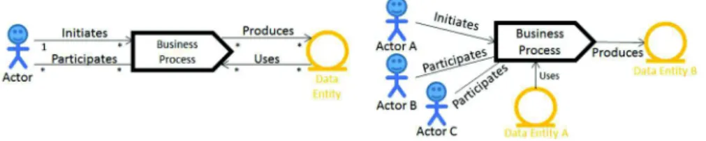
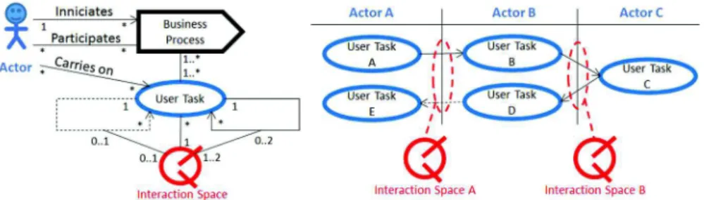
The relation between BPs and Data Entities is useful to design the enterprise BP Model, which relates BPs, Actors and Data Entities, increasing the perception on how a BP uses and produces certain business concepts from a higher level, which is useful for business management. We present the BP Model, by means of the appli-cation of the Process Use Cases Model [23] adapted to the current Goals notation. The meta-model and an example are presented in Figure 2.
Fig. 2. Business Process Model meta-model, and BP Model example.
Figure 2 presents the meta-model of the BP Model, in which it can be read that only one actor can “Initiate” a BP, but an unlimited number of Actors can participate in it, and also, that an unlimited number of Data Entities can be used and produced by a BP. It also presents an example where Actor A initiates the BP, Actors B and C participate in it, and the Data Entity A is used and the Data Entity B is produced. 4.2 Step 2 – User Task Identification
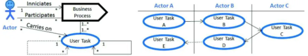
The User Task (UT) definition is derived from the concept of Essential Use Case (EUC) [19], which defines a Use Case as a “complete and meaningful task (carried out in relationship with a system)”. This definition is adapted to the enterprise context based on the principle that the Business Process (BP) is a sequence of UTs, and that each UT is carried out by a single Actor. Since a BP always has a limited number of tasks, all UTs can be considered as meaningful, thus, we abandon the “meaningful” term and define a UT as “A Complete User Task within a BP”. We also apply the
principle that an Actor (a user) never carries on two UTs consecutively and sepa-rately, which is an axiom that aims user performance and software development ef-ficiency by inducing the reduction of the articulatory distance of the UT i.e. the user’s effort [24], and by suggesting that the necessary tools should be provided using as little user interface implementation space as possible. If two UTs are consecutive, then they can be merged in a single sequence of acts, expressed by a single UT, leading to is completion in the same way.
The relations between UTs are what designs a BP. The consecutive relation is the most common, as it supports the most common BP flow. Yet, it is not sufficient to represent more complex services that must be available in different interaction points (identified as touchpoints by the Service Design domain) which usually have back-end support, and may be visited by the customer, but not necessarily and always in a pre-defined order. This need for flexibility can be attained by the definition of con-ditional relation, and thus, we further define it (the concon-ditional relation), meaning that the execution of a specific UT or BP path is conditioned to the will of the Actor. This reflects the case when an enterprise suggests its customers the execution of a given action in sequence of any other interaction but will never be sure that they will follow the suggestion, and yet continues to provide the remaining service.
Fig. 3. User Task meta-model and example.
Figure 3 presents the meta-model of the UT, in which further defines that one Actor can carry on many UTs and that a UT can also be carried out by many Actors defining cooperative collaboration; one BP can have many UTs; one UT can belong to many BPs; and UTs are related consecutively or conditionally. The example shows the initial UT being triggered by Actor A and consecutive B and C UTs being carried out by Actors B and C, and the response tasks, D and E (which path is conditional) being carried out by Actors B and A respectively.
4.3 Step 3 – Interaction Space Identification
The Interaction Space (IS) definition is derived from Wisdom original concept of Interaction Space, as a user interface space where the “user interacts with functions, containers and information in order to carry on a task”. We adapt this concept to the enterprise context by means of its generalization, in order to complementarily con-sider the support of the UT in person, as in any of the cases (remote or in person), the same Business Rules (BR) and Data Entities (DE) also apply. We (re)define the
IS extension as “The Space that supports a UT (with the same BRs and DEs)”. Hence, one IS supports the interaction between two users in person or remotely while each one carries on his own UT. Even if many UTs are carried by out many Actors in a cooperative way, the UTs will still be different. If two Actors carry on the same UT remotely, then they are performing cooperative work [25].
The identification of ISs is derived from the interaction between sequenced UTs, in order to support one Actor request and other Actor response, as in any case the same BRs and DEs apply. Figure 4 presents the meta-model that specifies that an IS supports many UTs based on the interaction between Actors, with at least a consec-utive relation and at most one conditional relation.
Fig. 4. Interaction Space meta-model and example.
The example shows the derivation of ISs in order to support the interaction between Actors A and B, and Actors B and C, by means of ISs A (a Request IS) and B (a Coordination IS) respectively, which is possible since the set of UTs A, B, D and E are subject to the same BRs and DEs, and the same happens in the case of UTs B, C and D. If another interaction between Actors A and B would occur (e.g. between User Task E and F), then a new IS should be defined (e.g. C) in order to support that interaction.
4.4 Step 4 – Business Rule Identification
The Business Rule (BR) definition is provided by DEMO notion of Action Rule, which defines a structure of decision (using pseudo-code) that applies restrictions to Object Classes concerning the execution of business Transactions. These restrictions are paradigmatic relations (considering a semiotic association) which are applied to the syntactic relations (also considering a semiotic definition) which exist between Data Entities (DE), in order to produce a new valuable and more complex business concept. Hence, we define BR as “A Restriction over DE’s Structural Relations”. BRs represent regulations or explicitly defined requirements that should be elicited in order to understand the restrictions which the user is subject to when carrying on a UT, and do not represent collaboration impositions with other Actors, since these rules are already expressed by the BP design.
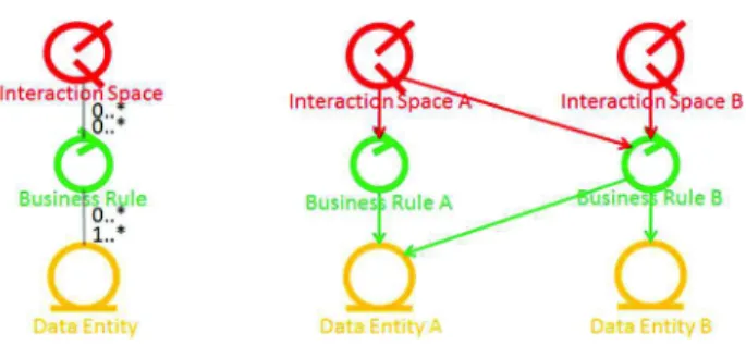
Fig. 5. Business Rules meta-model and example.
The BRs are the grounding foundation of the Information System’ Business Logic, as they are the only business-specific programmed class concerning this layer, the middleware of the system. The Business Logic will also be complemented in Step 8 – Business Logic Structuring, with programmed parts responsible for presentation and data management.
Figure 5 presents the meta-model, which defines that an IS can use many BRs, and that a BR can be used by many ISs, and also defines that a BR can use one to many DEs, and that a DE can be used by many BRs. The example shows that IS A uses BRs A and B, and that IS B is used only by BR B. It also defines that BR A uses DE A, and that BR B uses DEs A and B.
4.5 Step 5 – Data Entity Identification
The Data Entity (DE) definition is provided by Wisdom as a class of “Persistent In-formation about a Business Concept”. This means that persistency will be maintained by the Information System, and that it will enclose meaningful concepts which are recognized within the enterprise by those who have knowledge about it. DEs are related between each other, allowing a simple representation of reality which is made available by means of a Database application. Those "meanings" enclose attributes. In terms of common database objects, DEs are expressed as tables, and attributes are expressed by fields [26]. DEs are related between each other by means of semiotic syntactic relations, which are expressed in Goals using a UML association [27], also implying the definition of multiplicity between the related DEs. Multiplicity will typ-ically be of one-to-many or many-to-many. The definition of a specific multiplicity (e.g. 1 to 5) is uncommon, and should be expressed by a BR due its volatility (as it will eventually change). The definition of relations of one-to-one is also uncommon as in those cases the DEs meanings can usually be conciliated in a single DE.
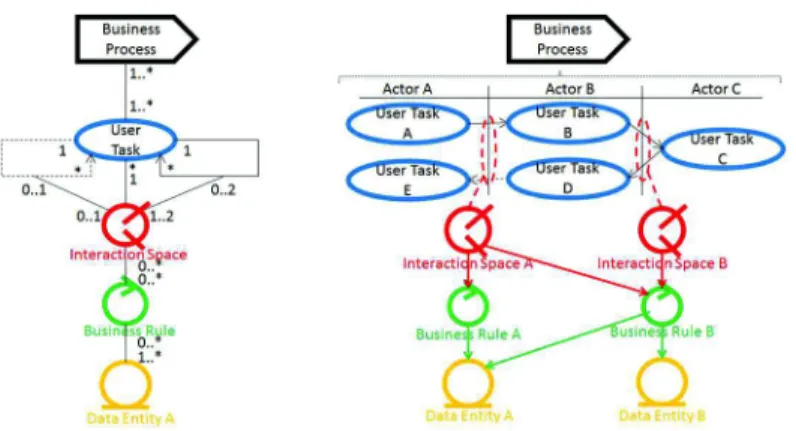
As mentioned in Step 1 - Business Process Identification, the identification of DEs should be carried along the BP design and consequential Steps, so that the analyst develops a well-defined notion of the concepts involved in the BPI under analysis. In the current Step, the DEs only need to be identified and related to the BRs in order to compose the Enterprise Structure, the final artefact of the Analysis Phase, as illus-trated in Figure 6, with the DEs as the support of the Enterprise Structure.
Fig. 6. Enterprise Structure meta-model and example.
The Enterprise Structure presented in Figure 6 is composed by every identified com-ponent until this moment and also by their relation to other comcom-ponents, with no changes. It represents a relation which is representative of the enterprise in terms of a logic that relates Business Processes (BP), User Tasks (UT), Interaction Spaces (IS), Business Rules (BR) and Data Entities (DE) in terms of dependency and func-tional specification. It can be used in order to identify the implications of changing the enterprise in terms of its impact in the software structure, since, changing BPs, UTs or BRs, which is common in the business management domain, will inevitably change the underlying information system to which the 3 lower levels layers (IS, BR and DE) are an inherent part, as they are also part of the Software Architecture.
5
Design Phase
The Design Phase details and complements the Enterprise Structure with new soft-ware-specific components that build-up the Software Architecture in a top-down methodological process in five Steps, which are presented in Sections: 5.1 (Step 6 – Task Model), 5.2 (Step 7 – User Interface Design), 5.3 (Step 8 – Business Logic Structuring), 5.4 (Step 9 - Database Structuring), and 5.5 (Step 10 – Software Archi-tecture Composition).
5.1 Step 6 – Task Model
The Task Model details User Tasks (UT) in order to obtain information to carry on the User Interface design, which happens in Step 7 – User Interface Design. The Task Model follows the technique applied in the Wisdom method in order to specify the UT in terms of User Intentions (steps that the user takes to complete the task) and System Responsibilities (that provide the necessary information), following a tradi-tional decomposition of an Essential Use Case (EUC) [19].
The decomposition of the UT in terms of User Intentions is carried out by means of the Concur Task Trees (CTT) technique [28]. CTT defines the User Intentions in the perspective of what the user wishes to do in order to obtain what the wants from the system and complete his UT. Each User Intention has an associated System Re-sponsibility (SR) that provides the necessary information to an Interactive Compo-nent that supports user interaction. The SR is a programmed class which is part of the Information System’ Business Logic.
The Task Model is represented using an Unified Modeling Language (UML) Ac-tivity Diagram [27], defining the flow of User Intentions that lead to the accomplish-ment of the UT. Each User Intention uses an Interaction Component that in its turn uses a SR. These are User Interface SRs. The last User Intentions always leads to SRs that manage information, which are Database SRs. In the case when new Data Entities are identified by means of the Task Model elaboration, then they must also be represented in the DE’s structure, a design task that will be specified in Step 9 - Database Structuring.
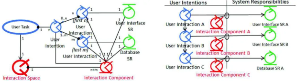
Fig. 7. Task Model’s meta-model and example.
Figure 7 presents the meta-model of the Task Model, where it can be read that a UT has many User Intentions, which have up to n initial User Interactions, and up to m last User Interactions that use m+n Interaction Components (which compose the Ag-gregation Space that will support the UT). Each Interaction Component supports one User Intention, and uses one User Interface SR or one Database SR. The example shows the decomposition of UT A of the designed BP, which has two initial User Intentions (A and B) and one final (C). User Intentions A and B relate to User Inter-face SRs A and B, and User Intention C relates to Database SR A, meaning that the UT can be carried out by means of 3 interactions, which are supported by 3 System Responsibilities and 3 Interaction Components.
5.2 Step 7 – User Interface Design
The User Interface Design is carried out by means of the application of the Behavior Driven Development (BDD) method [21] that further specifies each User Intention, and also frames it in terms of used Aggregation Spaces (AS), specifying the naviga-tion between User Tasks (UT). BDD is an agile software development method that
describes the system behavior based on a User-Centered Design (UCD) perspective, producing pseudo-code for User Interface specification. BDD specifies User Stories for a system feature (a UT) which is used within a certain scenario (the Aggregation Space), resulting in specific behavior which is generated by the system in the User Interface. The pseudo-code has the following syntax.
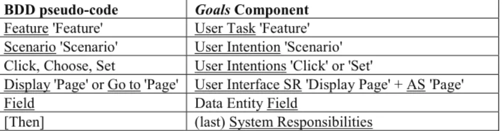
Given [State] When [Interaction] Then [System Behavior] Where [State] represents the actual the state of the system (which identifies the Ag-gregation Space where the UT occurs); [Interaction] is a flow of User Interactions; and, [System Behavior] is the expected outcome that triggers User Interface and Da-tabase System Responsibilities by means of Interaction Objects. BDD also specifies the Data Entities (DE) Fields used in each User Interaction. This specification facil-itates the mapping between Systems Responsibilities and DEs that occurs in Step 8 – Business Logic Structuring, and the completion of the Database specification that happens in Step 9 - Database Structuring. BDD’s User Stories are represented by an UML Activity Diagram, and use the pseudo-code which is presented in Table 3.
Table 3. Relation between BDD’ pseudo code syntax and Software Architecture’ components.
BDD pseudo-code Goals Component Feature 'Feature' User Task 'Feature' Scenario 'Scenario' User Intention 'Scenario' Click, Choose, Set User Intentions 'Click' or 'Set'
Display 'Page' or Go to 'Page' User Interface SR 'Display Page' + AS 'Page'
Field Data Entity Field
[Then] (last) System Responsibilities
Figure 8 presents the User Interaction meta-model and an example of a User Story that specifies each Task Model’ User Intentions in terms of Interaction Objects that match the already identified Interaction Components (IC) and SRs when there is only one User Interaction. And that divide in distinct Interaction Objects when there is more than one User Interaction, as in the case of User Interface SRs B.1 and B.2 that support two Interaction Objects (for “Type” and “Choose”) of IC B.
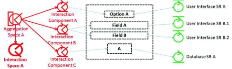
Figure 9 shows a representation of the User Interface which defines that the Aggre-gation Space A uses ICs A, B and C, which trigger the User Interface SRs A, B.1 and B.2, and Database System Responsibility A by means of the Interaction Objects pre-sented in the User Interface. The relation with Interaction Space A is inherited from the Enterprise Structure.
Fig. 9. User Interface Design example.
5.3 Step 8 – Business Logic Structuring
The Business Logic Structuring is carried out by defining the relations that each Sys-tem Responsibility (SR) and Business Rules (BR) has to Data Entities (DE), since the relation with the User Interface components is already established at this stage.
Figure 10 shows the manual mapping that was done between SRs and DEs. BR A is inherited from the Enterprise Architecture, as also is its relation with DE A. User Interface SR A has been mapped to DE A, and it is assumed that Field A and B identified in Step 7, belong to DE B, which is the reason why User Interface SRs B.1 and B.2 are related to DE B. By means of the analysis of the semantic of the Database SR A, it is assumed that there was a decision to relate it to both DEs A and B.
Fig. 10. Business Logic Structure example.
5.4 Step 9 - Database Structuring
The Database Structuring is now possible since all Data Entities (DE) are identified. Two DEs (A and B) have been identified, and DE B provides information for Fields A and B. We assume for purposes of example that DE A can only related to a single record in DE B, yet, on the contrary, any record in DE B can be related to many records in DE A. Figure 11 presents the Database Structure.
Fig. 11. Database Structure example.
5.5 Step 10 – Software Architecture Composition
The composition of the Software Architecture is carried out by relating in a single diagram every component identified by means of the execution of Steps 1 to 9, in-cluding the Business Process and User Tasks, and the hybrid Enterprise Structure and Software Architecture components of: Interaction Space, Business Rule and Data Entity, as well as the Software-Specific components.
Fig. 12. Software Architecture example.
Figure 12 presents the specified Software Architecture, in which the User Task (UT) A is now supported by Aggregation Space A and the underlying software structure, whilst UTs B, D and E are still not automated, reason why they are directly related to Interaction Space (IS) A. UT C and IS B and Business Rule B are not represented. The Software Architecture can be used in order to specify implementation respon-sibilities for a software development team and implementation priority. Priority will usually be from bottom-to-up, since the upper objects use the bottom ones. Applying the technique to the example architecture, the precedence of implementation would be: DE B (since it will be used in), DE A, Business Rule A, Database SR A, User Interface SRs B.1 and B.2, and only then User Interface SR A. Interaction Compo-nents A, B and C can follow any order, and once Interaction Space A and Business Rule A are developed, the Aggregation Space A can be implemented and tested.
6
Research Method and Validation
The research method of our approach was based on the question of if it would be possible to establish a relation between enterprise valuable concepts and the imple-mentation of a supporting system. And by placing the hypothesis that it is possible if a cross-consistent definition of concepts is established between the business concepts that specify human interaction, and from them, derive the components of the archi-tecture of a software system respecting specified business regulations. The cross-consistency between concepts is formalized by means of the application of the Cross-Consistency Assessment (CCA) [29] method to the Software Architecture compo-nents. Complementarily, we also use the CCA relation of concepts for purposes of architectural specification aiming software development clarification by means of providing implementation options insight.
The Software Architecture includes the five defined Software-Specific compo-nents (as previously presented in Table 2): Aggregation Space (AS), Interaction Component (IC), Interaction Object (IO), User Interface System Responsibility (UISR) and Database System Responsibility (DBSR); and the three hybrid Enterprise Structure components (which were also previously presented in Table 1): Interaction Space (IS); Business Rule (BR) and Data Entity (DE). Concerning software devel-opment, each component assumes distinct implementation options, as follows: · Aggregation Space (AS). A User Interface, a Web Page that includes other Web
Pages (Interaction Components), including an HTML presentation template [20]. · Interaction Component (IC). User Interaction for presentation and interaction support. A web Page, including an HTML template and a configuration artefact. · Interaction Object (IO). A User Interface object that allows interaction. An
HTML element e.g. Text Field; Checkbox; Radio Button: Dropdown List; Button. · User Interface SR (UI SR). Programmed routine that supplies a recordset to be used in one or more ICs. An SQL Server Stored Procedure, View, or JAVA pro-grammed class.
· Database SR (DB SR). Programmed routine that receives a recordset and saves it in the Database. An SQL Server Stored Procedure or JAVA programmed class. · Interaction Space (IS). Programmed routine that can be invoked by any
Soft-ware-Specific component in order to validate the data received in the User Inter-face, and sent to the Database.
· Business Rule (BR). Programmed routine that provides validation about the data which is transferred between the Interface and the Database.
· Data Entity (DE). Tables and Fields [26].
The Software Architecture components are presented in Figure 13 from top to down (from the AS to DE), according to the nature of their relation of usage i.e. the component on top uses and depends on the component on the lines below to properly work [27]. We define four types of relations concerning Software Architecture spec-ification:
· Architectural Usage - Underlined correct sign ( ü ). Goals architectural relations. Define relations between components which are generated by means of the appli-cation of the Goals method, and which are part of its meta-model, as presented throughout Sections 4 and 5.
· Allowed Usage – Correct sign (ü). Relations that can be applied for the purpose of architectural optimization. Mostly represent: reuse (ü1), of the components by itself by means of architectural observation, IS invocation (ü2), for purpose of the data validation, or direct usage of DE by IS (ü3), meaning that no restrictions are applied in this case.
· Contingency Usage – Wrong sign (û). Which are relations that that should not occur, but that yet can represent a useful trade-off, as they can simplify implemen-tation, however introducing architectural disorganization: between Software-Spe-cific components (û1), or related to the Enterprise Structure components (û2), as BRs should always be accessed by ISs and not directly, and also as DEs should be access by means of UI or DB SRs, and not by User Interface components. · Restricted Usage – Wrong underlined sign ( û ). Relations that should not exist,
as the IO should never make use of itself, and well as the BR, in order to promote business regulations organization.
Fig. 13. CCA validation of cross-consistency.
Hence, the cross-consistency of concepts between the Enterprise Structure and the Software Architecture components is achieved by means of the relation between the AS and the IS, providing support for the human interaction and business regulation execution, supporting our hypothesis. The AS also establishes the relation with the Software-Specific components by means of the Interaction Components and their Interaction Objects, namely with the User Interface and Database SRs, which use Data Entity elements, which are also common to the Enterprise Structure, providing full traceability between business and software implementation.
7
Conclusions
Our approach inherently aims at facilitating requirements elicitation, focuses on user needs, and simplifies traceability between business requirements and software im-plementation, which matches project management needs and user involvement in the Software Development Process, in what we believe that is the more important con-tribution of our work. The base strategy, based on Business Process Improvement (BPI), fits most successfully sized projects, as based on The Standish Group statisti-cal reports, projects under 1 M$ (one million dollars), in which cost most BPI fit into, are believed to be up to 10 times more successful than 10 M$ projects [4].
Our approach is suitable for in-house development in Small and Medium Enter-prises (SME), as it produces a controllable set of elements for a single BP organiza-tional change, which will usually be implemented with great efficiency (concerning man-hours work) by programmers with knowledge of the domain, and also defines an agile and straightforward logic, which suits SME needs for development perfor-mance. This induces iterative enterprise and information system continuous devel-opment which is compatible with the Agile Develdevel-opment manifesto [30], at an en-terprise scale.
8
Future Work
Future work mostly concerns the development of a toll for the application of the Goals method, as we believe from the long term use of the presented concepts, that the Goals structure is sufficiently well-defined in order to define a Platform-Specific Model (PIM) that can be used for full-stack MVC code generation. In this way, we open the space to predict software development effort with higher accuracy, and ul-timately identify successful enterprise and software development patterns.
References
1. The Standish Group. Chaos Report 2014. (2014)
2. Valente, P., Aveiro, D., Nunes, N.: Improving Software Design decisions towards en-hanced Return of Investment. In: Proceedings of ICEIS 2015, pp. 388-394. (2015) 3. Morgenshtern, O., Raz, T., Dvir, D.: Factors affecting duration and effort estimation
er-rors in software development projects. In: IST, V. 49, pp. 827-837. (2007) 4. The Standish Group. Chaos Report 2013. (2013)
5. Gerogiannis, V., Kakarontzas, G., Anthopoulos, L., Bibi, S., Stamelos, I.; The SPRINT-SMEs approach for software process improvement in small-medium sized software de-velopment enterprises. In: Proceedings of ARCHIMEDES III. (2013)
6. Kervel, S., Dietz, J, Hintzen, J., Meeuwen, T., Zijlstra, B.: Enterprise Ontology driven Software Engineering. In: Proceedings of ICsoft 2012. (2012)
7. Pombinho, J.: Value-oriented Enterprise Transformation - Design and Engineering of Value Networks. PhD Thesis, University of Lisbon – IST. (2014)
8. Archimate Foundation. Archimate Made Practical. (2008).
9. Völzer, H.: An overview of BPMN 2.0 and its potential use. In: BPMN 2010 Lecture Notes in Business Information Processing, V. 67, pp. 14-15, Springer. (2010)
10. Gareis, R.: 'Management by projects': the management approach for the future. In: Inter-national Journal of Project Management, V. 7(4), pp. 243-249. (1989)
11. Cannon, D.: ITIL Service Strategy. ISBN: 978-0113313044. (2011)
12. Schwaber, K.: Agile Project Management with Scrum (Developer Best Practices). ISBN: 978-0735619937. (2004)
13. Beck, K.: Embracing change with extreme programming. In: Computer, V. 32(10), pp. 70-77. (1999)
14. Grundy, J.: Foreword by John Grundy: Architecture vs Agile: competition or coopera-tion?. In: Agile Software Architecture, ISBN: 978-0124077720. (2013)
15. Sousa, K., Mendonça, H., Vanderdonckt, J., Rogier, E., Vandermeulen, J.: User interface derivation from business processes. In: Proceedings of SAC 2008, pp. 553-560. (2008) 16. Sukaviriya, N., Sinha, V., Ramachandra, T., Mani, S., Stolze, M.: User-Centered Design
and Business Process Modeling: Cross Road in Rapid Prototyping Tools. In: LNCS, Pro-ceedings of INTERACT 2007, pp. 165-178. (2007)
17. Nunes, N.: Object Modeling for User-Centered Development and User Interface Design: The Wisdom Approach. PhD Thesis, Universidade da Madeira. (2001)
18. Dietz, J.: Enterprise Ontology - Theory and Methodology. Springer-Verlag Berlin Hei-delberg, ISBN: 978-3540331490. (2006)
19. Constantine, L.: Human Activity Modeling - Toward a Pragmatic Integration of Activity Theory and Usage-Centered Design. Springer. (2009)
20. Costa, D., Nóbrega, L., Nunes, N.: An MDA Approach for Generating Web Interfaces with UML ConcurTaskTrees and Canonical Abstract Prototypes. In: LNCS, V. 4385. (2007)
21. Chelimsky, D., Astels, D., Helmkamp, B., North, D., Dennis, Z., Hellesoy, A.: The Rspec Book. ISBN: 1934356379. (2010)
22. Zukowski, J.: The Model-View-Controller Architecture. In: John Zukowski's Definitive Guide to Swing for Java 2, ISBN: 978-1430252511. (1999)
23. Valente, P. Goals Software Construction Process: Goal-Oriented Software Development. VDM Verlag Dr. Müller, ISBN: 978-3639212426. (2009)
24. Winckler, M., Freitas, C., Palanque, P., Cava, R., Barboni, E.: Usability aspects of the in-side-in approach for ancillary search tasks on the web. In: IFIP TC13 Conference on Hu-man-Computer Interaction 2015 (INTERACT), pp. 207-226. (2015)
25. Grudin, J. Computer-Supported Cooperative Work: History and Focus. In: Computer, v.27, pp. 19-26. (1994)
26. Awang, M., Labadu, N.: Transforming Object oriented Data Model to Relational Data Model. In: New Computer Architectures and their Applications, V. 2(3), pp. 402-409. (2012)
27. Booch, G., Jacobson, I., Rumbaugh, J.,: The Unified Modeling Language Users Guide. Addison-Wesley. (1998)
28. Paternò, F.: Model-Based Design and Evaluation of Interactive Applications. (1999) 29. Ritchey, T.: Principles of cross-consistency assessment in general morphological
model-ling. In: Acta Morphologica Generalis, V. 4. (2015)
30. Agile Alliance: Agile Manifesto. Retrieved 18-10-2016: http://agileman-ifesto.org/iso/en/principles.html