OATAO
O
pen
A
rchive
T
oulouse
A
rchive
O
uverte
(OATAO)
OATAO is an open access repository that collects the work of some Toulouse
researchers and makes it freely available over the web where possible.
This is
version published in:
Official URL:
To cite this version:
Any correspondence concerning this service should be sent to the repository administrator:
tech-oa [email protected] p-toulouse .fr
E
ffect of trivalent chromium process on fatigue lifetime of 2024-T3
aluminium
alloy
Myriam
Akanou
a,b,
Romain Saillard
a,
Benoit Fori
b,
Christine Blanc
a,
Gregory Odemer
a,⁎a CIRIMAT, Université de Toulouse, CNRS, INPT-ENSIACET, 4 Allée Emile Monso, CS 44362, 31030 Toulouse Cedex 4, France bMecaprotec Industries, 34 Boulevard de Joffrery, BP 30204, 31605 Muret Cedex, France
Keywords: Aluminium alloy Fatigue lifetime Conversion coating Crack initiation A B S T R A C T
The effect of a new alternative trivalent chromium conversion process on fatigue lifetime of a 2024-T3 alumi-nium alloy was investigated. The decrease in fatigue-life induced by coating process was related to the dis-solution of coarse intermetallic particles during the deoxidation pre-treatment preceding the conversion layer growth.
1. Introduction
Thanks to its high strength/weight ratio, good mechanical proper ties and corrosion resistance, 2024 T3 aluminium alloy (AA) is widely used in the aeronautic industry. Nevertheless, its heterogeneous mi crostructure increases its susceptibility to localised corrosion such as intergranular corrosion, local preferential dissolution or pitting corro sion for example. It was usually shown that local dissolution and pitting corrosion were related to major alloying elements, i.e. copper and magnesium, which are involved in the formation of intermetallic coarse particles (IMCs)[1 6]. These particles, e.g. Al2CuMg (S phase) and Al Cu Mn Fe type, can be anodic or cathodic and even change of polarity compared to the aluminium matrix[7,8]leading to galvanic coupling processes and preferential dissolution or pitting corrosion [9,10]. As discussed later in this paper, these forms of corrosion are regularly observed during conversion processes.
Until now, conversion processes based on hexavalent chromium were used extensively and successfully to improve the corrosion re sistance of 2xxx series AA[11 14]. However, the recent REACH reg ulation (Registration, Evaluation and Authorisation of CHemicals) has decided to ban hexavalent chromium for health and environment considerations. So aircraft manufacturers have developed new conver sion methods based on Trivalent Chromium Process (TCP).
According to the relative novelty of this type of surface treatment, literature data are very rare or even nonexistent on the effect of these new conversion coatings on fatigue properties of aluminium alloys. However, on some aspects, a parallel can be drawn here with anodi sation process, which has been more largely studied. Indeed, despite the benefits obtained in terms of corrosion protection, the anodic films have
a detrimental effect on the fatigue life in particular by promoting crack initiation[15 18].
One explanation for this result was related to the surface pre treatment and particularly to the deoxidation step. During deoxidation step, dissolution of the matrix around IMCs was observed in several works, depending on deoxidation conditions (i.e. composition of the desmuttting bath, immersion time, temperature…) and nature of IMCs [19 23]. Concerning the influence of anodised coatings on fatigue be havior, Shahzad et al.[19]and Priet et al.[24]have shown for AA2214 and AA2024, respectively that all crack initiation sites under fatigue solicitations started from pits formed during the deoxidation step whereas very few started from anodic coating. However, in the com plete absence of pitting corrosion during surface treatments, concerning specifically anodised samples, fatigue cracks initiate in the coating in high stress regions whereas they initiate at the interface between coating and substrate in low stress regions[16,25]. The roughness of the treated surfaces, by TCP or anodising, could play a role too as usually seen in numerous works on fatigue[22,26 28].
In this work, the effect of a new alternative TCP on fatigue behavior of AA2024 T3 was studied in ambient air. To determine the role of the deoxidation step on fatigue lifetime, fatigue tests have been performed on samples only deoxidised by comparison with samples completely treated.
2. Material and experimental procedures 2.1. Material
The material studied was AA2024 cold rolled 3 mm thin sheet with ⁎Corresponding author.
E-mail address: [email protected](G. Odemer). https://doi.org/10.1016/j.msea.2018.11.099
Table 1
Chemical composition of AA2024 (weight percent).
Elements Cu Mg Mn Zn Fe Si Tl Cr Zr Ni Al wt% 4.4 1.4 0.51 0.17 0.15 0.08 0.02 0.01 0.01 54ppm Bal
2
¾
•
4
•
5¾
Predegreasing Rinsing Rinsing Rinsing Rinsing(reverse osmosis {reverse osmosis (reverse osmosis (reverse osmosis
water) water) water) water}
Pre-treatmentstep Conversion layer growth step
1. Predegreasing 2. Oegreasing 3. Oeoxidation 4. Conversion 5. Post-treatment
Acetone Alkaline solution Su lfo-nitro-f erric solution ZR(IV) sait Earth sait
pH =9 pHs 1 3.8s pH S4.0 4.2 s pHs 5.3
Fig. 1. Characteristics of the different TCP steps.
the chemical composition given in Table 1. The alloy was provided in
the T3 metallurgical state, i.e. hot rolled, cold rolled, solution heat treated, water quenched, stress relieved and naturally aged at room temperature.
2.2. TCP characteristics
The whole TCP, developed by Socomore, is schematically presented in Fig. 1. This process included a first step of pre treatment followed by
a second step of conversion layer growth. The TCP conditions were
detailed in a previous paper (29). Finally, a non contact 3D Surface
Profiler was used in optical interferometry mode to measure the surface
topology of the treated samples.
2.3. Tensile and fatigue tests
To determine the relevant stress levels to apply for fatigue tests,
preliminary tensile tests were conducted at 25
•
c
on uncoated andcoated fiat dog bone tensile samples (2 mm thickness, 3 mm width,
20 mm gage length) machined in the L TL plane along the L direction of
the cold rolled 3 mm thin sheet at a constant strain rate of 10-3 s-1.
Stress controlled uniaxial fatigue tests were performed at 25
•
c,
inambient air. Fatigue life tests were performed using a 20 Hz sine wave
with a stress ratio of R
=
0.1 on "hourglass" fatigue samples (2 mm thickness, 3 mm width at the mid length, 32 mm gage length) ma chined in the same plane and direction in the thin sheet than tensile samples.Before the experiments, ail tensile and fatigue samples were ground,
including edges. The edges and the heads of samples were protected by
silicone during surface treatments.
2.4. Optical and transmission electron microscopy obse,vations
An Optical Microscope was used to determine the grain size after an
electrochemical etching. Scanning Electron Microscopy (SEM) coupled
with Energy Dispersive X ray spectroscopy allowed to characterize
IMCs. Finally, a SEM with a Field Emission Gun and a Transmission
Electron Microscope (TEM) were used to observe intergranular pre
cipitates and, both intergranular and intragranular hardening pre
cipitates, respectively. The details of sample preparation are given in
previous paper (29).
3. Results and discussion
3.1. Microstructures
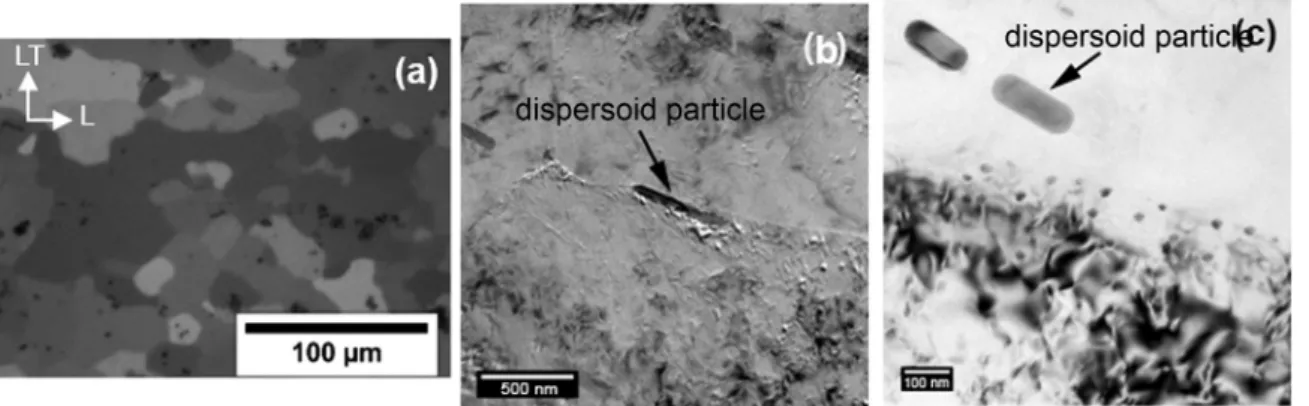
M2024 T3 microstructure has been already characterised finely in
a previous work (29). Only main results are reminded here. Average
grain sizes of about 22 µm in the longitudinal (rolling) direction and
19.2 µm in the long transverse direction were measured (Fig. 2a). SEM
observations showed two types of IMCs, i.e. Al~g particles (mean
surface area close to 2.9 µm2) and Al Cu Mn Fe type IMCs (mean sur
face area close to 6.8 µm2). At a finer scale, 200 nm dispersoids were
also visible (shown by black arrows in Figs. 2b and 2c); they were
composed of Cr, Zr or Mn. No intergranular precipitation was visible as
well as Guinier Preston Bagaryatsky (GPB) zones (30). However,
hardness values (under a 200 g loading) close to 143 HV compared to
123 HV for a freshly treated material led to assume the presence of GPB
zones due to natural ageing.
3.2. Eff ect of TCP on the tensile properties of AA2024 T3
The tensile mechanical characteristics of uncoated and coated
M2024 T3 are summarised in Table 2. No significant difference was
observed between uncoated and coated samples mainly due to the low
thickness of the conversion layer, i.e. 135nm (29). On the basis ofthese
tests, YSo.2% value was determined close to 380 MPa.
3.3. Eff ect of surface treatments on fatigue lifetime
Fatigue life curves are presented in Fig. 3. lt
was
first of interest to note that the fatigue lifetime was qui te similar between deoxidised andcoated samples and substantially lower compared to uncoated samples. This result suggested that deoxidation process was the main step of the TCP responsible for the fatigue lifetime decrease.
The second noticeable result was that no effect of deoxidation or complete TCP was seen on fatigue life curves at high stress levels. It was necessary to reach intermediate and low stress levels to observe a de crease of fatigue lifetime due to surface treatments, i.e. around one order of magnitude at 320 MPa. This result suggested that, at high stress levels, for uncoated, deoxidised and coated samples, the same type of surface defects were responsible for crack initiation contrary to the lower stress levels for which new initiation site(s) was(were) probably effective for deoxidised and coated samples. This (these) site(s) was (were) identified on the basis of fracture surfaces observations by SEM and roughness measurement/mapping.
3.4. Effect of surface treatments on fatigue crack initiation
At first, roughness measurements were performed for uncoated, deoxidised and coated samples (Table 3). According to literature data [31], the average roughness of the coated sample was close to the initial roughness of the uncoated and polished material. On the contrary, the roughness of the deoxidised sample was significantly higher, twice that of both uncoated and coated samples. Therefore, the coating step seemed to reduce the average roughness of deoxidised samples. How ever, strong local variations were observed, for both deoxidised and coated samples, in relation with the reactivity of S Al2CuMg particles, during deoxidation step[9,10,22,29]leading to local dissolution pro cesses (Fig. 4). Harvey et al. have shown that these phenomena could be compared to corrosion processes occurring in NaCl solutions[32]. In deed, S Al2CuMg particles are more reactive than Al Cu Mn Fe particles
Fig. 2. Optical (a) and TEM (b, c) observations of AA2024-T3.
Table 2
Tensile properties of uncoated and coated samples of AA2024-T3.
Tensile properties YS(MPa) UTS (MPa) εf(%)
Uncoated 2024-T3 380 580 18.3 Coated 2024-T3 380 580 17.8
Fig. 3. S-N curves of uncoated, deoxidised and coated samples of AA2024-T3. Table 3
Roughness of uncoated, deoxidised and coated surfaces of AA2024-T3.
Uncoated samples Deoxidised samples Coated samples Roughness (RMS) 7 nm 14.7 nm 7.5 nm 0.92YS02 350 0.89YS02 340 0.87YS02 330 0.84YSo.2 320 -;; ,J{
..
t. ~1
ü t.
0.81YS0_, =310.
~ ~ 0.79YS0_, 300 ._ T3 uncoated • T3 deoxidised eT3 coated 0.76YS02 290 0.74YSo.2 280 10 8min55s..
.
10 1h23rrio.
Number of cycles to failure 10
13h53min
Fatigue test duration
dispersoid
particlfc)
/
..
' 10 138h53minbecause their potential is more negative than this of the aluminium matrix. Changes in their composition during corrosion processes lead to an inversion in polarity that induces a dissolution of the surrounding matrix andfinally the removal of the particles from the surface. Con cerning Al Cu Mn Fe particles, only the dissolution of the matrix around the particles was observed due to their higher potential by comparison with the matrix.
The fact that fatigue life curves of deoxidised and coated samples were similar while the surfaces of the corresponding samples presented a different average roughness suggested that the average roughness was not afirst order parameter responsible for the decrease in fatigue life time. A more local approach of the surface state, considering in parti cular the removal of S Al2CuMg particles from the sample surface, had to be considered.
SEM observations of fracture surfaces after fatigue tests are pre sented in Figs. 5 and 6for uncoated and deoxidised/coated samples, respectively. Independently of the surface treatment and the applied stress level, the fracture surfaces presented three distinct zones char acterised by different fracture modes: the crack initiation zone followed by the crack propagation zone and then the ductilefinal fracture with dimples (Fig. 5a). A crystallographic propagation, i.e. quasi cleavage fracture, characterised by river patterns, was observed on the fracture surfaces (Fig. 5b) associated with striation patterns (Fig. 5c). This crystallographic propagation is generally associated to environment and more particularly to water vapor and/or hydrogen [33 36]. In deed, depending on environmental conditions and material, water vapor or hydrogen resulting from the chemical dissociation of the ad sorbed water vapor molecule on the fresh surfaces at the crack tip can assist crack propagation. In this work, crack initiation was always lo calised on IMCs for uncoated samples, regardless of the stress level, due
to the localisation of plasticity on these particles, leading to their shearing (Fig. 5d).
Concerning the deoxidised and the coated samples, quasi cleavage propagation and ductilefinale fracture were not modified by compar ison with uncoated specimens. Only crack initiation sites were modified for intermediate and low stress levels as already suggested by S N curves (Fig. 3), whereas, for high stress levels, IMCs were always pre ferential crack initiation sites. Indeed, according to the roughness map, the removal of S Al2CuMg particles during deoxidation process could explain the premature crack initiation as seen inFig. 6.Fig. 6a presents an observation of one lateral face of a deoxidised fatigue sample. Local dissolution processes induced by IMCs clusters were clearly visible as well as the preferential initiation of a secondary crack from these sur face topology irregularities. This result was also observed under the fracture surface of coated samples as highlighted byFig. 6b. Once again it is possible to observe, for a secondary crack, a preferential crack path along local dissolution zones confirming the role of the deoxidation step on the decrease in fatigue lifetime. It could be possible that IMCs re activity was exacerbated after machining and mirror polishing of samples, which could be confirmed by Kelvin probe Force Microscopy [37]. Nevertheless, the premature crack initiation on surface defects induced by deoxidation processes localised on IMCs can explain the decrease of the fatigue lifetime for both deoxidised and coated samples at intermediate and low stress levels and the relative low scattering of fatigue lifetime values measured in this work.
4. Conclusions
The effect of a new alternative TCP on fatigue lifetime of AA 2024 T3 was investigated. A noticeable decrease in fatigue lifetime was ob served for deoxidised and coated samples at intermediate and low stress levels suggesting a modification of crack initiation sites. According to surface map and fracture surface observations, it was shown that deoxidation treatment was the main responsible for this decrease in fatigue properties that could be explained by the removal of S Al2CuMg particles from surface material during the deoxidation step. Finally, at high stress levels, crack initiation took place on IMCs whereas, for lower stress levels, surface topology irregularities due to the deoxidation step was more detrimental.
Fig. 4. Roughness map of a coated sample.
Fig. 5. Rupture surface observations by SEM of uncoated AA2024-T3 after fatigue tests. Global view (a), crack propagation zone: rivers (b) and striation patterns (c) and shearing of IMCs on sample lateral surface (d).
Acknowledgments
This work was performed in the framework of the NEPAL FUI project. CIRIMAT wasfinancially supported by the French Ministry of Economy and Industry (BPI France), the Région Occitanie/Pyrénées Méditerranée and the European Union (FEDER/ERDF).
References
[1] X. Zhou, C. Luo, T. Hashimoto, A.E. Hughes, G.E. Thompson, Study of localized corrosion in AA2024 aluminium alloy using electron tomography, Corros. Sci. 58 (2012) 299–306.
[2] A. Boag, A.E. Hughes, A.M. Glenn, T.H. Muster, D. McCulloch, Corrosion of AA2024-T3 Part I: localised corrosion of isolated IM particles, Corros. Sci. 53 (2011) 17–26.
[3] R. Grilli, M.A. Baker, J.E. Castle, B. Dunn, J.F. Watts, Localized corrosion of a 2219 aluminium alloy exposed to a 3.5% NaCl solution, Corros. Sci. 52 (2010) 2855–2866.
[4] R.G. Buchheit, R.P. Grant, P.F. Hlava, B. McKenzie, G.L. Zender, Local dissolution phenomena associated with S phase (Al2CuMg) particles in aluminum alloy
2024‐T3, J. Electrochem. Soc. 144 (1997) 2621–2628.
[5] T. Hashimoto, X. Zhang, X. Zhou, P. Skeldon, S.J. Haigh, G.E. Thompson, Investigation of dealloying of S phase (Al2CuMg) in AA 2024-T3 aluminium alloy
using high resolution 2D and 3D electron imaging, Corros. Sci. 103 (2016) 157–164. [6] R.P. Wei, C.M. Liao, M. Gao, A transmission electron microscopy study of
con-stituent-particle-induced corrosion in 7075-T6 and 2024-T3 aluminum alloys, Metall. Mater. Trans. A 29 (1998) 1153–1160.
[7] G.M. Brown, K. Kobayashi, Nucleation and growth of a chromate conversion coating on aluminum alloy AA 2024-T3, J. Electrochem. Soc. 148 (2001) B457–B466.
[8] N. Birbilis, R.G. Buchheit, Electrochemical characteristics of intermetallic phases in aluminum alloys an experimental survey and discussion, J. Electrochem. Soc. 152 (2005) B140–B151.
[9] C. Blanc, B. Lavelle, G. Mankowski, The role of precipitates enriched with copper on the susceptibility to pitting corrosion of the 2024 aluminium alloy, Corros. Sci. 39 (1997) 495–510.
[10] K.D. Ralston, N. Birbilis, M.K. Cavanaugh, M. Weyland, B.C. Muddle,
M.K.W. Marceau, Role of nanostructure in pitting of Al–Cu–Mg alloys, Electrochim. Acta 55 (2010) 7834–7842.
[11] M. Kendig, S. Jeanjaquet, R. Addison, J. Waldrop, Role of hexavalent chromium in the inhibition of corrosion of aluminum alloys, Surf. Coat. Technol. 140 (2001) 58–66.
[12] L. Xia, R.L. McCreery, Chemistry of a chromate conversion coating on aluminum alloy AA2024‐T3 probed by vibrational spectroscopy, J. Electrochem. Soc. 145 (1998) 3083–3089.
[13] J. Zhao, G. Frankel, R.L. McCreery, Corrosion protection of untreated AA‐2024‐T3 in chloride solution by a chromate conversion coating monitored with Raman spectroscopy, J. Electrochem. Soc. 145 (1998) 2258–2264.
[14] E. Eichinger, J. Osborne, T. Van Cleave, Hexavalent chromium elimination: an aerospace industry progress report, Met. Finish. 95 (1997) 36–41.
[15] B. Lonyuk, I. Apachitei, J. Duszczyk, The effect of oxide coatings on fatigue prop-erties of 7475-T6 aluminium alloy, Surf. Coat. Technol. 201 (2007) 8688–8694. [16] R. Sadeler, Effect of a commercial hard anodizing on the property of a 2024-T6
aluminium alloy, J. Mater. Sci. 41 (2006) 5803–5809.
[17] R.G. Rateick, T.C. Binkowski, B.C. Boray, Effect of hard anodize thickness on the fatigue of AA6061 and C355 aluminium, J. Mater. Sci. Lett. 15 (1996) 1321–1323. [18] E. Cirik, K. Genel, Effect of anodic oxidation on fatigue performance of 7075-T6
alloy, Surf. Coat. Technol. 202 (2008) 5190–5201.
[19] M. Shahzad, M. Chaussumier, R. Chieragatti, C. Mabru, F. Rezai-Aria, Effect of sealed anodicfilm on fatigue performance of 2214-T6 aluminum alloy, Surf. Coat. Technol. 206 (2012) 2733–2739.
[20] G.E. Thompson, L., C. Zhang, J.E. Smith, P. Skeldon, Boric/sulfuric acid anodizing of aluminum alloys 2024 and 7075:film growth and corrosion resistance, Corros. Sci. 55 (1999) 1052–1060.
[21] J.H. Liu, M. Li, S.M. Li, M. Huang, Effect of the microstructure of Al 7050-T7451 on anodic oxide formation in sulfuric acid, Int. J. Mineral., Metal. Mater. 16 (2009) 432–438.
[22] X. Verdalet-Guardiola, J.-P. Bonino, S. Duluard, B. Fori, C. Blanc, Influence of the alloy microstructure and surface state on the protective properties of trivalent chromium coatings grown on a 2024 aluminium alloy, Surf. Coat. Technpl. 344 (2018) 276–287.
[23] V.J. Qi, A. Němcová, J.R. Walton, X. Zhou, P. Skeldon, G.E. Thompson, Influence of pre- and post-treatments on formation of a trivalent chromium conversion coating on AA2024 alloy, Thin Solid Films 616 (2016) 270–278.
[24] B. Priet, G. Odemer, C. Blanc, G. Kévin, L. Arurault, Effect of new sealing treatments on corrosion fatigue lifetime of anodized 2024 aluminium alloy, Surf. Coat. Technol. 307 (2016) 206–219.
[25] J.A.M. Camargo, H.J.C. Voorwald, M.O.H. Cioffi, M.Y.P. Costa, Coating residual stress effects on fatigue performance of 7050-T7451 aluminum alloy, Surf. Coat. Tech. 201 (2007) 9448–9455.
[26] M. Suraratchai, J. Limido, C. Mabru, R. Chieragatti, Modelling the influence of machined surface roughness on the fatigue life of aluminium alloy, Int. J. Fat. 30 (2008) 2119–2126.
[27] G. Deng, K. Nagamoto, Y. Nakano, T. Nakanishi, Evaluation of the Effect of Surface Roughness on Crack Initiation Life, in: Proceedings of the Proceedings of the 12th International Conference on Fracture (ICF12), July12-17, Ottawa, Canada, 2009. [28] C. Wiesner, H.U. Kunzi, B. Ilschner, Characterization of the topography of turned surfaces and its influence on the fatigue life of AL-7075, Mater. Sci. Eng. A 145 (1991) 151–158.
[29] R. Saillard, B. Viguier, G. Odemer, A. Pugliara, B. Fori, C. Blanc, Influence of the microstructure on the corrosion behaviour of AA2024 aluminium alloy coated with a trivalent chromium conversion layer, Corros. Sci. 142 (2018) 119–132. [30] Y.A. Bagaryatsky, Structural changes on aging Al–Cu–Mg alloys, in: Dokl Akad
SSSR, 1952, pp. 397–559.
[31] L. Li, G.P. Swain, A. Howell, D. Woodbury, G.M. Swain, The formation, structure, electrochemical properties and stability of trivalent chrome process (TCP) coatings on AA2024, J. Electrochem. Soc. 158 (2011) C274–C283.
[32] T.J. Harvey, A.E. Hughes, S.G. Hardin, T. Nikpour, S.K. Toh, A. Boag, D. McCulloch, M. Horne, Non-chromate deoxidation of AA2024-T3: sodium bromate–nitric acid (20–60 °C), Appl. Surf. Sci. 254 (2008) 3562–3575.
[33] J. Petit, G. Henaff, C. Sarrazin-Baudoux, Environmentally-assisted fatigue in the gaseous atmosphere, in: J. Petit, P. Scott, I. Milne, R.O. Ritchie, B. Karihaloo editors (Eds.), Environmentally-assisted Fracture, 6 Comprehensive structural integrity, Amsterdam, 2003, pp. 211–280.
[34] G. Henaff, G. Odemer, A. Tonneau-Morel, Environmentally-assisted fatigue crack growth mechanisms in advanced materials for aerospace applications, Int. J. Fat. 29 (2007) 1927–1940.
[35] C.T. Liu, E.H. Lee, C.G. McKamey, An environmental effect as the major cause for room-temperature embrittlement in FeAl, Scr. Metall. Mater. 23 (1989) 875–880. [36] W. Elber, The significance of crack closure, in: Damage tolerance in aircraft
struc-tures, in: Proceedings of the PA: American Society for Testing and Materials, Toronto, ASTM STP 486, Ontario, Canada, Philadelphia; 1971, pp. 230–242. [37] L. Lacroix, Mécanismes de corrosion localisée de l′alliage d′aluminium 2024.
Apport de la microscopie à force atomique (AFM) couplée au mode Kelvin (KFM) et des alliages modèles, Thesis of the University of Toulouse, France, Toulouse, France, 2008.