This is an author-deposited version published in :
http://oatao.univ-toulouse.fr/
Eprints ID : 2788
O
pen
A
rchive
T
OULOUSE
A
rchive
O
uverte (
OATAO
)
OATAO is an open access repository that collects the work of Toulouse researchers and
makes it freely available over the web where possible.
To link to this article
: DOI:
10.1016/j.electacta.2009.01.074
URL :
http://dx.doi.org/10.1016/j.electacta.2009.01.074
To cite this version
:
Gibilaro, M. and Massot, Laurent and Chamelot, Pierre and Taxil ,
Pierre ( 2009)
Co-reduction of aluminium and lanthanide ions in
molten fluorides : application to cerium and samarium extraction
from nuclear waste.
Electrochimica Acta, vol. 53 (n° 22). pp.
5300-5306. ISSN 0013-4686
Co-reduction of aluminium and lanthanide ions in molten fluorides:
Application to cerium and samarium extraction from nuclear wastes
M. Gibilaro, L. Massot
∗, P. Chamelot, P. Taxil
Laboratoire de Génie Chimique UMR 5503, Département Procédés Electrochimiques, Université de Toulouse, 31062 Toulouse Cedex 9, France
a r t i c l e
i n f o
Keywords: Fluorides Electrochemical co-reduction Alloys formation Aluminium Lanthanidesa b s t r a c t
This work concerns the method of co-reduction process with aluminium ions in LiF–CaF2 medium
(79–21 mol.%) on tungsten electrode for cerium and samarium extraction. Electrochemical techniques such as cyclic and square wave voltammetries, and potentiostatic electrolyses were used to study the co-reduction of CeF3and SmF3with AlF3. For each of these elements, specific peaks of Al–Ce and Al–Sm
alloys formation were observed by voltammetry as well as peaks of pure cerium and aluminium, and pure samarium and aluminium respectively. The difference of potential measured between the solvent reduc-tion and the alloy formareduc-tion suggests expecting an extracreduc-tion efficiency of 99.99% of each lanthanide by the process.
Different intermetallic compounds were obtained for different potentiostatic electrolysis and were characterised by Scanning Electron Microscopy with EDS probe.
The validity of the process was verified by carrying out cerium and samarium extractions in the form of Al–Ln alloy; the extraction efficiency was 99.5% for Ce(III) and 99.4% for Sm(III).
1. Introduction
Since 1991, alternative solutions for radioactive wastes treat-ment have been examined by several nuclear research programs. The aim of Partitioning and Transmutation (P&T) is to reduce signif-icantly the amount of radiotoxic nuclear wastes after fuel recycling, by consuming the most radiotoxic elements (Np, Pu, Am, Cm). The separation process for actinides (An) and lanthanides (Ln) has to be completely achieved. Uranium, neptunium and plutonium are actually extracted for further recycling with the hydrometallurgical process PUREX.
The pyrochemical route is mainly envisaged for the reprocessing of advanced fuels and transmutation blankets which are expected to have a high content of Pu and minor actinide and high burn up. The interest of pyroprocesses is based on the properties of the salt phase: high radiation resistance, high thermal resistance and they are almost transparent to neutrons. Pyrometallurgical processes are also attractive for the dissolution of some of the proposed fuels or blankets such as inert matrix, which are very difficult or impossible to be dissolved in aqueous media. An alternative route would be pyrochemical processes using molten salts for the separation of An from Ln.
Several separation techniques are examined as precipitation with oxide ions[1], electrorefining[2–4]or reductive extraction
∗ Corresponding author. Tel.: +33 561 558 194; fax: +33 561 556 139.
E-mail address:[email protected](L. Massot).
[5]. Reductive extraction is considered as the more efficient process for the French option (fluoride/aluminium) and it is also considered within the Japanese process in molten chloride with bismuth. Here, lanthanides LnF3and actinides AnF3to be extracted are placed in a
molten solution in contact with a liquid metallic phase acting as a reductive agent A.
The separation efficiency is highly dependant on the metallic phase and the most promising liquid solvent for An–Ln separation is the aluminium[6]. Conocar et al.[7]investigated the An–Ln sep-aration in LiF–AlF3at 830◦C and demonstrated experimentally that
more than 99.3% of Pu and Am initially present in the molten solvent are recovered in the aluminium phase according to the following scheme:
AnF3(solution) + Al(metal) = An(metal) + AlF3(solution) (1)
Hence, this process allows the selective extraction of actinides while lanthanides remain in the salt. The next reprocessing step is the lanthanides recovery in order to recycle the fluoride solvent.
Nourry[8]succeed in extracting three lanthanides (Sm, Gd, Nd) in LiF–CaF2using electroreduction on a reactive cathode (Cu or Ni)
in the form of alloys Cu/Ln or Ni/Ln. The alloy formation allows the lanthanide deposition to be shifted in the anodic sense which is called depolarisation. Nourry showed experimentally that, as well as on copper as on nickel cathodes, the lanthanide extraction effi-ciency was about 100%.
The present work is dedicated to the lanthanides extraction: the co-reduction by the co-reduction of Ln ions with aluminium
ions. The two different elements studied, cerium and samarium, are relevant in the list of fission products. Their behaviour in the molten fluorides is typical of Ln elements: three exchanged electrons and one or two reduction steps.
2. Experimental
- The cell consisted of a vitreous carbon crucible placed in a cylin-drical vessel made of refractory steel and closed by a stainless steel lid cooled inside by circulating water. The inner part of the walls was protected against fluoride vapours by a graphite liner containing the experimental crucible. The experiments were performed under an inert argon atmosphere (U-grade: less than 5 ppm O2), previously dehydrated and deoxygenated using a
purification cartridge (Air Liquide). The cell was heated using a programmable furnace and the temperature was measured using a chromel–alumel thermocouple. A more detailed description of the device can be found in previous papers of our laboratory such as the one referred in[9].
- The electrolytic bath consisted of the eutectic LiF/CaF2 (SDS
99.99%) mixture (79/21 molar ratio). Before use, it was dehy-drated by heating under vacuum (3 × 10⁻²mbar) from the room
temperature up to its melting point (762◦C) for 72 h. For
pro-viding aluminium and neodymium ions, aluminium fluoride AlF3
(SDS 99.95%) and lanthanide fluoride (SDS 99.99%) powders were introduced into the bath through a lock chamber under argon gas atmosphere.
- Electrochemical equipment: all electrochemical studies and electrolyses were performed with an Autolab PGSTAT 30 poten-tiostat/galvanostat controlled by a computer using the research software GPES 4.9.
- Electrochemical techniques: cyclic voltammetry, square wave voltammetry and potentiostatic electrolyses were used for the investigation of the aluminium–lanthanide co-reduction process. - Characterisation of reduction products: after electrolysis runs, the cathode surface was examined by Scanning Electron Microscopy (LEO 435 VP) equipped with an EDS probe (Oxford INCA 200) for determining the composition of the alloys.
2.1. Analytical setting
For investigations on electrochemical behaviour of the fluoride baths, we used the following cell:
Tungsten wire (1 mm diameter) was used as a working elec-trode with a surface area determined from its immersion depth measurement in the bath after withdrawing from the cell. The aux-iliary electrode was a vitreous carbon rod (3 mm diameter) with a large surface area. Potentials were referenced to a platinum wire (0.5 mm diameter) immersed in the molten electrolyte, acting as a quasi-reference electrode Pt/PtOx/O2−[10].
2.2. Extraction setting
Compared with the previous setting, the extraction experiments need specific arrangements:
1- The reference electrode is a nickel 1 mm diameter wire immersed in a mixture of LiF–CaF2–NiF2 (1 mass%), placed in
a boron nitride basket. This reference electrode was proved to be reliable in molten fluoride baths[11]. Moreover, the insula-tion from the electrolytic bath ensures the invariability of its potential with the change of composition of the electrolyte. 2- The anode was made of vitreous carbon and was isolated in a
graphite compartment containing LiCl–LiF–CaF2eutectic
mix-ture. The anodic reaction was the chlorine release; the electrode
compartmentalisation avoids gas and fluoride media mixing and re-oxidation of Al–Ln compounds cathodically formed. 3- The working electrode was a tungsten plate with a large surface
area (3 cm2).
3. Results and discussion
3.1. Co-reduction process overview
The co-reduction consists of a simultaneous reduction of two or more metallic ions on an inert electrode to form an alloy of the two metals. This process described by Brenner in aqueous media
[12]and more recently proposed by Taxil et al. in molten salts for nuclear wastes reprocessing[13]exhibits advantages for lan-thanides extraction compared to the use of a reactive electrode by avoiding intermetallic diffusion limitation and consumption of the anode material. Moreover, better selectivity is expected by this technique due to a possible correlation between the alloy compo-sition and the cathode potential imposed during electrolysis.
If R is the more reactive precursor, N the less reactive one and RxNythe alloy formed by co-reduction, the co-reduction process in
the case of two metallic ions, Rn+and Np+involves the following
reactions:
xRn++ne−=xR (I) yNp++pe−
=yN (II)
xR + yN = RxNy (III)
The overall process is:
xRn++yNp++(n + p)e−=RxNy (2)
The equilibrium potential of the system R/RxNycan be expressed
as:
ERn+/RxNy=ERn+/R−
RT
nF ln[aR(in RxNy)] (3) where ERn+/Ris the equilibrium potential of pure R element, T the
absolute temperature in K, n the number of exchanged electron, F the Faraday constant (96 500 C) and aR(in RxNy) the activity of R in
the intermetallic compound RxNy.
As aRin RxNyis less than one, it can be deduced that ERn+/R xNy>
ERn+/R.
Here the co-deposition of R with a more noble metal allows Rn+
to be reduced at a potential more anodic than the pure metal depo-sition: this “depolarisation effect” is similar to that is observed on reactive electrodes[14].
Co-reduction has been mainly used for boron base metal deposi-tion. Lantelme et al.[15]studied the electrodeposition of TiB2from
titanium and boron ions in NaCl–KCl–NaF. When both metallic ions are present in the melt, only one reduction peak is observed on the cyclic voltammogram corresponding to TiB2deposit, which is
shifted towards more positive values, than that of the pure boron deposition. This observation was confirmed by Ett et al.[16]and Wendt et al. in molten fluorides[17,18].
The selectivity of the co-reduction process was demonstrated by Cohen[19]for niobium–germanium alloys in LiF–KF. Several inter-metallic compounds (NbGe2, Nb3Ge2. . .) were prepared by varying
correlatively the metallic ion concentration in the bath and the electrolysis potential.
The present work is aimed at using the alloy formation technique for lanthanides extraction (Ce, Sm) in molten fluorides and at opti-mizing the technique by the selection of the electrolysis potential. The first part is a brief review of the main results on the electrochemical behaviour of aluminium and lanthanide fluorides obtained in our laboratory using the experimental setup 2.2 called
Fig. 1. (a) Cyclic voltammogram of the LiF–CaF2–CeF3(2.5 × 10⁻⁴mol cm−3) system
at 100 mV s−1and T = 840◦C[20]. Working electrode: W; counter electrode:
vitre-ous carbon; quasi-reference electrode: Pt. (b) Square wave voltammogram of the LiF–CaF2–CeF3system (2.5 × 10⁻⁴mol cm−3) at 9 Hz and T = 840◦C[20]. Working
electrode: W; counter electrode: vitreous carbon; quasi-reference electrode: Pt.
“analytical setting”. In the second part, the behaviour of the mix-ture of aluminium and lanthanide ions in the molten salt has been investigated in order to define the alloy composition as a function of the potential. Finally, the results of Ln extraction by co-reduction are presented.
3.2. Previous results on solutes electrochemical reduction on inert electrode
3.2.1. Cerium fluoride
The CeF3electrochemical reduction was investigated in LiF–CaF2
on an inert tungsten electrode at 840◦C[20]. It has been shown
that its reduction is a one step process exchanging 3 electrons and controlled by the diffusion of cerium ions in the melt.
Ce(III) + 3e−
=Ce (4)
On the cyclic voltammogram plotted at 100 mV s−1on a W
elec-trode (Fig. 1a), the reduction peak at −1.8 V vs. Pt is attributed to the cerium metal deposition and its re-oxidation peak is at about −1.55 V vs. Pt. The solvent reduction, corresponding to lithium deposit, takes place at −2 V vs. Pt.
Fig. 1b shows a square wave voltammogram plotted under the same conditions. The peak for cerium metal deposition is located at −1.72 V vs. Pt.
3.2.2. Samarium fluoride
Massot et al. [21] studied the electrochemical behaviour of samarium(III) ions in the eutectic mixture LiF–CaF2on a
molyb-denum electrode. It was demonstrated that SmF3is reduced in two
Fig. 2. (a) Cyclic voltammogram of the LiF–CaF2–SmF3(2.1 × 10⁻⁴mol cm−3) system
at 100 mV s−1and T = 840◦
C[21]. Working electrode: Mo; counter electrode: vitre-ous carbon; quasi-reference electrode: Pt. (b): Square wave voltammogram of the LiF–CaF2–SmF3system (2.1 × 10⁻⁴mol cm−3) at 9 Hz and T = 840◦C[21]. Working
electrode: Mo; counter electrode: vitreous carbon; quasi-reference electrode: Pt.
successive steps: Sm(III) + e−
=Sm(II) (5)
Sm(II) + 2e−
=Sm (6)
The second reduction step corresponding to the metal depo-sition is not observed in our molten media. On the cyclic voltammogram ofFig. 2a recorded at 100 mV s−1, only one
reduc-tion peak is observed at −1.25 V vs. Pt corresponding to Eq.(5). It was established that the electrochemical reduction process is controlled by the diffusion of Sm(III) ions in the solution.
This feature is confirmed by square wave voltammetry that exhibits a single symmetric peak typical of a soluble/insoluble reac-tion attributed to the Sm(III)/Sm(II) system at about −1.15 V vs. Pt.
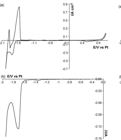
3.2.3. Aluminium fluoride
The work performed in our laboratory[22]on tungsten elec-trode at 860◦C concludes that the reduction of Al(III) in LiF–CaF
2is
controlled by the diffusion of aluminium ions in the melt and that it follows a single step process exchanging 3 electrons, as observed on the cyclic voltammogram presented inFig. 3a where only one wave at −1.25 V vs. Pt is present:
Al(III) + 3e−
=Al (7)
On the square wave voltammogram plotted at 9 Hz inFig. 3b, we can see one reduction peak at −1.2 V vs. Pt corresponding to aluminium deposition.
Fig. 3. (a) Cyclic voltammogram of the LiF–CaF2–AlF3(2.1 × 10⁻⁴mol cm−3)
sys-tem at 100 mV s−1and T = 860◦
C[22]. Working electrode: W; counter electrode: vitreous carbon; quasi-reference electrode: Pt. (b) Square wave voltammogram of the LiF–CaF2–AlF3system (2.1 × 10⁻⁴mol cm−3) at 9 Hz and T = 860◦C[22]. Working
electrode: Mo; counter electrode: vitreous carbon; quasi-reference electrode: Pt.
3.3. Co-reduction between aluminium and lanthanide ions 3.3.1. AlF3–CeF3system
The Al–Ce phase diagram[23] exhibits 5 intermetallic com-pounds Al11Ce3, AlCe3, AlCe2, AlCe, AlCe3. The following part will
be focused on the determination of their potential formation.
3.3.1.1. Electrochemical behaviour. Experiments were carried out on
an inert tungsten electrode at 840◦C with the analytical setting
described in Section2.1; the electrochemical behaviour of the Al–Ce system was investigated by cyclic voltammetry and square wave voltammetry. The same metallic ion concentrations as in each indi-vidual study above were used: [Al(III)] = 2.1 × 10⁻⁴mol cm−3 and
[Ce(III)] = 2.5 × 10⁻⁴mol cm−3. The cyclic voltammetry of this
mul-tiple system on W electrode is presented inFig. 4a. Four reduction peaks are observed:
•Ep= −1.25 V vs. Pt: this peak seems to be superimposed on the one of pure aluminium formation because the potential peaks are quiet similar and the current density is appropriately higher than for Al alone.
•Ep= −1.79 V vs. Pt: a similar situation is observed, with a peak for the mixture at the same potential and with enhancement of the current compared with pure cerium deposition.
•Ep= −1.43 V vs. Pt and Ep= −1.6 V vs. Pt: the additional reduc-tion peaks, comprised of the respective reducreduc-tion potentials of Al(III) into Al and Ce(III) into Ce, can be attributed to the aluminium–cerium co-reduction.
Fig. 4. (a) Cyclic voltammogram of the LiF–CaF2–AlF3–CeF3system (respectively
2.1 × 10⁻⁴and 2.5 × 10⁻⁴mol cm−3) at 100 mV s−1and T = 840◦C. Working electrode:
W; counter electrode: vitreous carbon; quasi-reference electrode: Pt. (b) Square wave voltammogram of the LiF–CaF2–AlF3–NdF3system (respectively 1.8 × 10⁻⁴and
2 × 10⁻⁴mol cm−3) at 9 Hz and T = 860◦
C. Working electrode: W; counter electrode: vitreous carbon; quasi-reference electrode: Pt.
The same distribution of peak potentials is observed more clearly in the square wave voltammogram of the mixture AlF3–CeF3
(Fig. 4b) on W electrode at 840◦C and a signal frequency of 9 Hz. The
presence of Al(III) and Ce(III) peaks together with new additional peaks of co-reduction between them are observed.
These preliminary experiments lead us to suppose that the co-reduction Al/Ce involves the formation of intermetallic compounds at well defined potentials in a potential range located between the deposition of each pure metal.
3.3.1.2. Co-deposition products analysis. In this section, each peak
of the voltammogram is attributed to a specific composition of the alloy compound.
Potentiostatic electrolysis runs were performed on a tung-sten electrode in LiF–CaF2by co-reduction of the respective ions.
The experimental conditions were: [Al(III)] = 2.1 × 10⁻⁴mol cm−3;
[Ce(III)] = 2.5 × 10⁻⁴mol cm−3; T = 840◦C; electrolysis time = 1200 s.
Just after each run, the electrode was quenched by a rapid with-drawal from the cell. Then, an EDS analysis, joined to the SEM observation of the sample cross section, allowed us to determine the composition of the phases observed on the micrographs.
Electrolyses were performed with a cathode potential previously defined by cyclic voltammetry.
The micrographics presented inFig. 5show that:
(i) at each electrolysis potential, one intermetallic compound is observed;
(ii) the new solid phase of the alloys is no adherent onto the substrate and is released within the molten salts solution.
Fig. 5. (a) Micrograph of the cross section of a tungsten wire after electrolysis.
Exper-imental conditions: T = 840◦C, E = −1.25 V vs. Pt, t = 1200 s. (b) Micrograph of the cross
section of a tungsten wire after electrolysis. Experimental conditions: T = 840◦
C,
E = −1.43 V vs. Pt, t = 1200 s. (c) Micrograph of the cross section of a tungsten wire
after electrolysis. Experimental conditions: T = 840◦
C, E = −1.79 V vs. Pt, t = 1200 s.
This adherence defect is presumably due to a specific nucle-ation phenomenon at the germinnucle-ation step that we still cannot explain.
The formation of intermetallic compounds at each electrolysis potential is reported below:
•E = −1.25 V vs. Pt: Al11Ce3deposit (Fig. 5a). 11Al(III) + 3Ce(III) + 42e−
=Al11Ce3 (8)
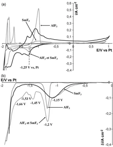
Fig. 6. (a) Cyclic voltammogram of the LiF–CaF2–AlF3–SmF3system (respectively
1.8 × 10⁻⁴and 5.2 × 10⁻⁴mol cm−3) at 100 mV s−1and T = 840◦
C. Working electrode: W; counter electrode: vitreous carbon; quasi-reference electrode: Pt. (b) Square wave voltammogram of the LiF–CaF2–AlF3–SmF3system (respectively 1.8 × 10⁻⁴
and 5.2 × 10⁻⁴mol cm−3) at 9 Hz and T = 840◦C. Working electrode: W; counter
elec-trode: vitreous carbon; quasi-reference elecelec-trode: Pt.
•E = −1.43 V vs. Pt and E = −1.6 V vs. Pt: Al3Ce deposit (Fig. 5b). 3Al(III) + Ce(III) + 12e−
=Al3Ce (9) •E = −1.79 V vs. Pt: AlCe3and AlCe deposits (Fig. 5c).
Al(III) + 3Ce(III) + 12e−
=AlCe3 (10) Al(III) + Ce(III) + 6e−
=AlCe (11)
3.3.2. Characterisation of AlF3–SmF3system
3.3.2.1. Electrochemical behaviour. The incomplete Al–Sm phase
diagram[24]exhibits 4 intermetallic compounds (Al3Sm, Al2Sm,
AlSm and AlSm2) which could be obtained by co-reduction.
The simultaneous presence of aluminium and samarium ions produces a reasonable change in the individual electrochemical signal for each element as shown inFig. 6a recorded by cyclic voltammetry on W electrode at 100 mV s−1.
Only shoulders and not well defined peaks are observed in
Fig. 6a; a cathodic current, plotted at E < −1.25 V vs. Pt (pure alu-minium deposition) is certainly due to Al–Sm alloy formation.
The square wave voltammetry, which is known as a more sen-sitive method than cyclic voltammetry, produces with a better characterisation of the system. InFig. 6b, the square wave voltam-mogram plotted on a W electrode of the metallic ions coexisting in the solution exhibits the following reduction peaks or shoulders:
•E > −1.2 V vs. Pt: the current seems to be the sum of the current of Sm(III)/Sm(II) and Al(III)/Al. The current signal superimposes
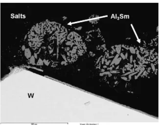
Fig. 7. Micrograph of the cross section of a tungsten wire after electrolysis.
Experi-mental conditions: T = 840◦
C, E = −1.45 V vs. Pt, t = 1200 s.
the reduction peak of Al(III) reduction in the decreasing part of Sm(III) reduction.
•E < −1.2 V vs. Pt: new reduction peaks or shoulders (−1.45, −1.53 and −1.66 V vs. Pt) are comprised of the reduction of Al(III) in pure aluminium and the solvent reduction being specific of the co-reduction process.
3.3.2.2. Co-reduction products analysis. The same
methodol-ogy as previously for Al–Ce alloy characterisation was used; potentiostatic electrolysis was performed at the following exper-imental conditions: [Al(III)] = 2.1 × 10⁻⁴mol cm−3; [Sm(III)] =
2.5 × 10⁻⁴mol cm−3; T = 840◦C; electrolysis time = 1200 s. The
electrode was quenched after each run and the deposited product was analysed by an EDS probe. The electrolysis potential was determined from the square wave voltammogram ofFig. 6b. The results are indicated below:
•E < −1.15 V vs. Pt.
At these potentials, the electrochemical reduction of Sm(III) into Sm(II) occurs. None of the electrolyses lead to Al–Sm alloy deposition.
•E > −1.2 V vs. Pt.
The same electrolysis conditions have been applied for
E > −1.2 V vs. Pt and only one alloy was observed on the
micro-graph presented inFig. 7: Al3Sm.
3Al(III) + Sm(II) + 11e−
=Al3Sm (12) The Al–Sm alloy of uniform composition is released in the salt and seems to coalesce in 100 mm balls, each of them exhibiting a noticeable porosity.
3.4. Co-reduction application to lanthanide extraction 3.4.1. Experimental procedure
The extraction was realised on tungsten electrode in LiF–CaF2
media at T = 840◦C.
The experimental setup is described in the Experimental Section
2.2with a specific reference electrode and anodic compartment. The use of a reliable reference electrode Ni(II)/Ni insulated from the electrolytic bath ensures the stability of the potential reference which is an essential condition for lengthy potentiostatic electrol-yses runs. So, in the electrolysis part of the article, potentials are referenced to the NiF2/Ni electrode.
Extraction electrolyses were performed on a W plate at the potential predefined on previous square wave voltammogram cor-responding to Al3Ln formation.
Fig. 8. Current density evolution during electrolysis measured by square wave
voltammetry. Experimental conditions: T = 840◦
C, f = 9 Hz; working electrode: W; counter electrode: vitreous carbon; reference electrode: NiF2/Ni.
The tungsten electrode was replaced every 3 h and periodically the progress of the reaction was measured by recording on a tung-sten wire cyclic and square wave voltammograms.
3.4.2. Aluminium cerium extraction process
The electrolysis potential was chosen from the square wave voltammogram (Fig. 4b) at −1.43 V and the initial concen-trations in metallic ions were: [Al(III)] = 1.8 × 10⁻⁴mol cm−3;
[Ce(III)] = 5.6 × 10⁻⁵mol cm−3.
As mentioned above, the process was controlled by periodically recording square wave voltammograms of the solution. Typical square wave voltammograms are presented in Fig. 8. A signifi-cant decrease of the current density is observed, correlated to the decrease of Al(III) and Ce(III) ion concentration in the bath dur-ing the extraction process. We noticed that the current density decreased more quickly at the beginning of the electrolysis than at longer times.
Electrolyses were performed for 120 h to obtain a cathodic current density value approaching zero on the square wave voltam-mogram. The extraction efficiency was calculated with ICP analysis of the bath after electrolysis and was equal to 99.5% for cerium(III).
3.4.3. Aluminium samarium extraction process
The same methodology was applied to the aluminium– samarium co-extraction process. The initial concentrations were [Al(III)] = 2.2 × 10⁻⁴mol cm−3; [Sm(III)] = 6 × 10⁻⁵mol cm−3 and
the electrolysis potential was −1.45 V.
Fig. 9. Current density evolution during electrolysis measured by square wave
voltammetry. Experimental conditions: T = 840◦C, f = 9 Hz; working electrode: W;
Fig. 9represents the electrochemical signal recorded by square wave voltammetry for successive electrolysis time: 0, 30, 60 and 130 h. An important decrease of the current density can be noted, showing that the metallic ions concentration decreases during the extraction.
After 130 h, the signal recorded is approaching zero. An ICP analysis indicated that 99.4% of the samarium fluoride has been extracted.
4. Conclusion
Cyclic and the square wave voltammograms in Al–Ce and Al–Sm fluoride solutions showed evidences. Specific electrochemical sys-tems for the co-reduction of aluminium and lanthanide ions were identified in the potential range between pure Al and Ln metal deposition. Each reduction waves observed was correlated to Al–Ln intermetallic compounds, further identified on the cathode samples with SEM observation and EDS analysis after a short electrolysis run. For the Al–Ce system, when increasing cathodic potential, the cerium content in the alloy increases. For the Al–Sm co-reduction, only one intermetallic compound was obtained: Al3Sm.
These preliminary experiments allowed the expected forma-tion of defined compounds to be correlated with specific cathode potentials.
Extraction electrolyses using these potential data were success-fully performed with extraction efficiencies of 99.5% for cerium and 99.4% for samarium. The co-reduction technique is promis-ing for other lanthanide elements; thus this work opens the way to extract other fission products from nuclear wastes by using the co-reduction technique with aluminium.
Acknowledgements
The authors express their thanks to the PCR RSF Thorium and GDR Paris from the PACEN program (French program from
National Centre For Scientific Research) for financial support of this work.
References
[1] D. Lambertin, J. Lacquement, S. Sanchez, G. Picard, Proc. ATALANTE, Nimes, 2004.
[2] M. Iizuka, T. Koyama, N. Kondo, R. Fujita, H. Tanaka, J. Nucl. Mater. 247 (1997) 183.
[3] J. Serp, M. Allibert, A. Le Terrier, R. Malmbeck, M. Ougier, J. Rebizant, J.P. Glatz, J. Electrochem. Soc. 152 (3) (2005) C167.
[4] L. Cassayre, R. Malmbeck, P. Masset, J. Rebizant, J. Serp, P. Soucek, J.P. Glatz, J. Nucl. Mater. 360 (2007) 49.
[5] L. Rault, M. Heusch, M. Allibert, F. Lemort, X. Deschanel, R. Boen, Nucl. Technol. 139 (2002) 167.
[6] O. Conocar, N. Douyere, J. Lacquement, J. Nucl. Mater. 344 (2005) 136. [7] O. Conocar, N. Douyere, J.P. Glatz, J. Lacquement, R. Malmbeck, J. Serp, Nucl. Sci.
Eng. 153 (2006) 253.
[8] Christophe Nourry, PhD thesis, 2007, Université Paul Sabatier, Toulouse, France.
[9] P. Chamelot, P. Taxil, B. Lafage, Electrochim. Acta 39 (17) (1994) 2571. [10] A.D. Graves, D. Inman, Nature 208 (1965) 481.
[11] P. Taxil, Z. Qiao, J. Chim. Phys. 82 (1) (1985) 83.
[12] A. Brenner, Electrodeposition of Alloys, vol. 1, Academic Press, New York, 1963.
[13] P. Taxil, P. Chamelot, L. Massot, C. Hamel, J. Miner. Met. 39 (2003) 177. [14] C. Nourry, L. Massot, P. Chamelot, P. Taxil, J. New Mater. Electrochem. Syst. 10
(2007) 117.
[15] F. Lantelme, A. Barhoun, E.M. Zahidi, J.H. von Barner, Plasmas Ions 2 (1999) 133.
[16] G. Ett, E.J. Pessine, Electrochim. Acta 44 (1999) 2859.
[17] H. Wendt, K. Reuhl, V. Schwarz, Electrochim. Acta 37 (2) (1992) 237. [18] H. Wendt, K. Reuhl, V. Schwarz, J. Appl. Electrochem. 22 (1992) 161. [19] U. Cohen, J. Electrochem. Soc. 130 (7) (1983) 1480.
[20] M. Gibilaro, PhD thesis, “Co-réduction électrochimique de l’aluminium et des lanthanides en milieu fluorures fondus; application au traitement pyrochim-ique des effluents nucléaires”, Toulouse, France, 2008.
[21] L. Massot, P. Chamelot, P. Taxil, Electrochim. Acta 50 (2005) 5510.
[22] M. Gibilaro, L. Massot, P. Chamelot, P. Taxil, J. Alloys Compd. (2008), doi:10.1016/ j. jallcom.2008.03.115.
[23] K.H.J. Buschow, J.H.N. Van Vucht, Philips, Res. Rep. 22 (1967) 233. [24] K.H.J. Buschow, A.S. Van der Goot, J. Less-Common Met. 24 (1971) 117.
![Fig. 3. (a) Cyclic voltammogram of the LiF–CaF 2 –AlF 3 (2.1 × 10 − 4 mol cm − 3 ) sys- sys-tem at 100 mV s − 1 and T = 860 ◦ C [22]](https://thumb-eu.123doks.com/thumbv2/123doknet/3722542.111182/5.892.423.827.111.583/fig-cyclic-voltammogram-lif-caf-alf-mol-sys.webp)