Any correspondence concerning this service should be sent to the repository administrator:
[email protected]
Identification number: DOI:10.1243/09544054JEM1257
Official URL:
http://dx.doi.org/10.1243/09544054JEM1257
This is an author-deposited version published in:
http://oatao.univ-toulouse.fr/
Eprints ID: 8662
To cite this version:
Jasinevicius, Renato Goulart and Andreeta, Marcello B. R. and Fossa, João S.
and Hernandez-Rodriguez, Antônio Carlos and Duduch, Jaime G. and Demont,
Philippe and Puech, Pascal Brittle and ductile removal modes observed during
diamond turning of carbon nanotube composites. (2009) Proceedings of the
Institution of Mechanical Engineers, Part B: Journal of Engineering
Manufacture, vol. 223 (n° 1). pp. 1-8. ISSN 0954-4054
O
pen
A
rchive
T
oulouse
A
rchive
O
uverte (
OATAO
)
OATAO is an open access repository that collects the work of Toulouse researchers and
makes it freely available over the web where possible.
Brittle and ductile removal modes observed during
diamond turning of carbon nanotube composites
R G Jasinevicius1*, M R B Andreeta2, J S Fossa2, A C Hernandes2, J G Duduch1, P Demont3, and P Puech4
1Departmento de Engenheria Mec^anica, Universidade de S~ao Paulo, S~ao Carlos, S~ao Paulo, Brazil
2Grupo de Crescimento de Cristais e Materiais Cer^amicos, Universidade de S^ao Paulo, S^ao Carlos, S^ao Paulo, Brazil 3
Laboratoire de Physique des Polym"eres, Institut Carnot-Cirimat, Universit#e Paul Sabatier Toulouse III, Toulouse, France
4CEMES, Toulouse, France
DOI: 10.1243/09544054JEM1257
Abstract: Ultraprecision diamond turning was used to evaluate the surface integrity of a carbon nanotube (CNT) composite as a function of the cutting conditions and the percentage of CNT in the epoxy matrix. The effects of cutting conditions on the chip morphology and surface roughness were analysed. The results showed that an increase in the percentage of CNT may influence the mechanism of material removal and consequently improve the quality of the machined surface. When smaller quantities of CNT (0.02 and 0.07 wt %) are present in the matrix, microcracks form within the cutting grooves (perpendicular to the cutting direction). This indicates that the amount of CNT on the epoxy matrix may have a direct influence on the mechanical properties of these materials. Chips removed from the CNT composite samples were analysed by scanning electron microscopy in order to correlate the material removal mechanism and the surface generation process. The area average surface roughness Sa was
influenced by the material removal mechanism (Saranging from 0.28 to 1.1 mm).
Keywords: carbon nanotubes, nanocomposite material, micromachining, single-point diamond turning, non-destructive evaluation, surface finish
1 INTRODUCTION
Ultraprecision diamond turning is an established machining technique applied to the manufacturing of several products such as contact lenses, mirrors, infra red lenses, etc. The variety of materials already studied in terms of machinability using single-point diamond tools range from optical polymers, non-ferrous metals, and optical glasses to semiconductor crystals. The results obtained in terms of surface roughness and surface form may be smaller than a few tens of nanometres (peak to valley) and smaller than a few hundred nanometres respectively. The typical cutting conditions in ultraprecision diamond turning imply that the material removal process be
governed by the microinteraction between the dia-mond cutting edge (a few tens of nanometres) and the workpiece material. Because of this, the micro-structure of the workpiece can play a fundamental role in the cutting results.
Considerable attention has been paid to carbon nanotubes (CNTs) owing to their outstanding mechanical properties and high electrical and ther-mal conductivity [1–5]. Adding CNTs to an epoxy matrix has the effect of increasing the electrical conductivity at low filling as a result of the low percolation threshold for nanotubes (between 0.04 and 0.2 wt % CNTs depending on the dispersion and amphiphilic molecule assistance) [6]. Consequently, improvement of the electrical and mechanical prop-erties of composites has prompted many initiatives in recent years [7]. In terms of manufacturing engi-neering it is important to have materials such as CNT epoxy resin composites that present very high strength–weight and modulus–weight ratios. This can *Corresponding author: Departmento de Engenheria Mec^anica,
Escold de Engenharia de S~ao Carlos, Universidade de S~ao Paulo, C.P. 359, CEP 13566-590, S~ao Carlos, S~ao Paulo, Brazil. email: [email protected]
be done by decreasing the density of epoxy and increasing the amount of CNT in the matrix, which provides very good mechanical properties. Since turning is dynamic, new behaviours of the material could be expected with percolation because CNTs are good thermal conductors and can quickly dissipate the energy in the network. CNTs are still expensive, and changing the properties with a small amount is a challenge. With dynamic changes, an improvement can be expected in the material response to manu-facturing processes and also in the lifetime of the product. For example, CNTs change the wear rate of tyres, contributing to energy savings, or stop crack propagation after an impact.
It is known that surface properties affect the per-formance of high-quality components/products. Mechanical processes of material removal, applied to the manufacturing of industrial parts and compo-nents, may generate deleterious damage to the mechanical properties of materials. Several factors affect the surface integrity of high-quality compo-nents when they are machined, including surface roughness, microstructure, residual stresses, and microhardness variation.
In addition, very little effort has been made so far to change the CNT composite surface and bulk properties induced by industrial processing methods [8]. Surface integrity is of extreme importance in order to guarantee the performance of the material during its application. For example, surface rough-ness may drastically affect the fatigue properties of these materials. The comprehension of CNT/ma-chining and its effects upon material response is considered an important issue for applications in the aeronautic industry. For the tyre industry, energy saving with low rolling resistance and low wear rates is also an interesting challenge.
Based upon the aspects pointed out, it is important to understand the mechanism of material removal in machining in order to improve the material response to manufacturing processes in terms of surface roughness, form, and surface damage.
The single-point diamond turning process was used to evaluate the material removal mechanism and the surface integrity of a CNT composite in respect of two aspects: variation in cutting conditions and variation in the weight fraction of CNTs in the epoxy matrix.
2 EXPERIMENTAL PROCEDURE
Carbon nanotube–epoxy resin nanocomposite sam-ples (15 mm · 30 mm, and 1.5 mm thick) with differ-ent concdiffer-entrations of CNT (see Table 1) were face turned with a round-nosed single-crystal diamond tool (Contour Fine Tooling"
). The CNTs were
pre-pared by the catalytic chemical vapour deposition method (CCVD). Selective reduction at 1000C in a methane–hydrogen (18%CH4) atmosphere of a solid
solution of a transition metal oxide Mg0.95Co0.05led
to the formation of small-diameter CNTs with 1–3 walls (for more details, see references [6] to [8]). After the reaction, the unreacted catalytic particles were dissolved in diluted (3.7 per cent) hydrochloric acid and CNTs were recovered. High-resolution electron microscopy images show the presence of individual CNTs and small bundles of CNTs with an average diameter of 2.4 nm. The nanotubes were mainly single walled (SW) and double walled (DW). A dis-persion of CNTs in water was first kept in an ultra-sonic bath for 1 h and stirred. No surfactants were used. CNT–epoxy resin composites were prepared by dispersion (in weight) of CNTs ranging from 0.04 to 0.4 wt %. The liquid epoxy resin was added to the dilute suspension of nanotubes and water was eva-porated at 100C. The mixture was then mechani-cally stirred for 1 h at 2000 r/min. The hardener was added, and the whole mixture was mechanically stirred for 15 min and then cast into a teflon mould and degassed for 20 min under vacuum. The nano-composite was cured at 120C for 20 min and at 145C for another 8 h. In order to enhance CNT dis-persion in the epoxy matrix, palmitic acid (PA) can be added as a dispersing agent before hardener addition. Other samples were prepared by varying the CNT content from 0.02 to 0.8 wt %, with a CNT–PA weight ratio of 1:1.
The percolation threshold is associated with a change in the conductivity value from 10 15S/cm to 10 5S/cm. Table 1 presents the values for the com-posites. The samples have been selected with a small amount of CNT in order to find what can be expected below and above the threshold. Sample 1 is an insu-lating nanocomposite because the CNT content is below the threshold percolation. Sample 2 (0.07 wt % CNTs) is very close to the threshold percolation, while samples 3 and 4 are largely above the threshold.
Single-point diamond turning tests were carried out on a commercially available ultraprecision diamond turning machine, the Aspheric Surface
Table 1 Composition of the CNT epoxy resin samples
Sample CNT content (wt %) Observation
1 0.02 0.02 per cent palmitic acid
Percolation < 0.04 per cent
2 0.07
3 0.3 0.3 per cent palmitic acid
Percolation < 0.04 per cent
4 0.4 0.4 per cent palmitic acid
Generator Rank Pneumo ASG 2500. The cross-feed direction was outside to inside. The cutting tool had a nose radius of 0.76 mm, a 0
rake angle, and a 12 clearance angle. No cutting fluid was used, as the material is very soft and there is no need for cooling or lubrication. The feed rate and depth of cut applied in the cutting tests are described in Table 2. The spindle speed was kept constant at 1000 r/min. The test provided ductile- and brittle-mode machining resulting in different surface finishes.
3 RESULTS AND DISCUSSION 3.1 Surface roughness results
Figures 1(a) to (d) show three-dimensional AFM images of the samples cut under the same conditions (feed rate 15 mm/rev, depth of cut 20 mm), diamond turned in the ductile and brittle modes. The cutting grooves are regularly spaced and run parallel with the cutting direction, which confirms the absence of chattering. Figures 1(a) and (b) show samples with the lowest CNT concentration. The feed marks of the tool are visible, but the surface shows small tears and pitting within the cutting grooves (across the cutting direction), most probably because of a more brittle cutting behaviour. This composite has a thermoset epoxy resin matrix, which also contributes to its brittleness. Cracks might originate at the tool tip and propagate into the newly formed surface, resulting in a fractured surface and adversely affecting the sur-face quality after diamond turning.
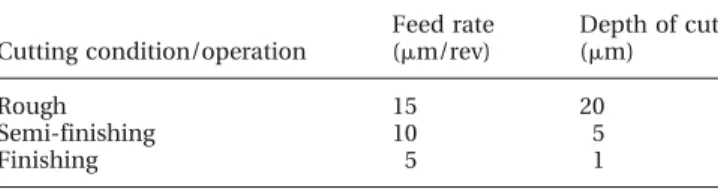
Table 2 Cutting conditions used in the face operation
Cutting condition/operation Feed rate (mm/rev) Depth of cut (mm) Rough 15 20 Semi-finishing 10 5 Finishing 5 1
Fig. 1 Three-dimensional images made by AFM of the surfaces generated under the rough cutting condition: (a) 0.02 wt% CNTs; (b) 0.07 wt % CNTs; (c) 0.3 wt % CNTs; (d) 0.4 wt % CNTs
The formation of microcracks seems to be related not only to the matrix being thermoset but also to the rake angle tool (0). Carr and Feger [9] investigated the influence of the rake angle on the surface finish of a brittle material (Vespel). According to the authors, the rake angle influences the direction of the cutting force. Their results demonstrated that the resulting
cutting force points into the workpiece, and the
machined surface presented a strong pit formation
when the rake angle was large and negative. It was also demonstrated that the force vector (resulting cutting force) points at the uncut surface when the rake angle is almost zero and reaches its most effec-tive value when the rake angle is slightly posieffec-tive (around þ2). The resulting cutting force, in this case, points slightly to the uncut surface. Conse-quently, microcracks that are normally formed in front of the tool would not penetrate the cutting
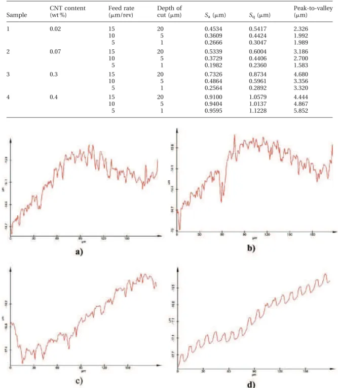
Table 3 Surface roughness analysis of the machined samples
Sample CNT content (wt %) Feed rate (mm/rev) Depth of cut (mm) Sa(mm) Sq(mm) Peak-to-valley (mm) 1 0.02 15 20 0.4534 0.5417 2.326 10 5 0.3609 0.4424 1.992 5 1 0.2666 0.3047 1.989 2 0.07 15 20 0.5339 0.6004 3.186 10 5 0.3729 0.4406 2.700 5 1 0.1982 0.2360 1.583 3 0.3 15 20 0.7326 0.8734 4.680 10 5 0.4864 0.5961 3.356 5 1 0.2564 0.2892 3.320 4 0.4 15 20 0.9100 1.0579 4.444 10 5 0.9404 1.0137 4.867 5 1 0.9595 1.1228 5.852
Fig. 2 Cross-sectional profile of the machined surfaces cut under the roughening operation: (a) 0.02 wt % CNTs; (b) 0.07 wt % CNTs; (c) 0.3 wt % CNTs; (d) 0.4 wt % CNTs
plane, leaving a crack-free surface. The area surface roughnesses Sawere 0.4534 and 0.5339 mm (Figs 1(a)
and (b) respectively). A closer examination of the machined surface (Fig. 1(c)) indicates that microtears are still present and brittle mode prevails, in spite of the increased concentration of CNT. The area surface roughness Saalso increases to 0.7326 mm. The sample
with the highest concentration of CNT presented a different surface finish, as shown in Fig. 1(d). The cutting grooves can be clearly seen and do not pre-sent any signs of the brittle behaviour, characteristic of normal thermoplastic machining of, for example, PMMA [10]. This may be related to the difference in density of CNTs in the epoxy matrix. However, the area surface roughness increased to 0.9595 mm for the finest finishing cutting condition. This is an unexpected result because the microtears within the cutting grooves in the samples with a lower
concentration of CNTs should have resulted in larger values of surface roughness. The complete surface roughness results under different cutting conditions and compositions (wt %) of CNTs are listed in Table 3.
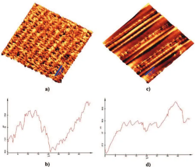
The peak-to-valley results presented in Table 3 correspond to the sample cross-section (Figs 2(a) to (d)) presented in Fig. 1. The cross-sectional profile of the sample with no pits replicates with good fidelity the tool path (feed rate 15 mm/rev), as shown in Fig. 2(d). The high surface roughness may be explained by an increase in material side flow during cutting. Figure 3 shows a comparison of two surfaces. Fig. 3(a) shows the three-dimensional image and Fig. 3(b) shows the cross-sectional profile of the machined surface under a feed rate of 5 mm/rev (finishing condition) with 0.07 wt % CNTs. Figure 3(c) shows the three-dimensional image and Fig. 3(d) shows
Fig. 3 Three-dimensional images made by AFM, showing a closer view of the machined cut grooves of the machined samples under different cutting conditions and percentage CNT: (a) 0.07 wt % CNTs, feed rate 5 mm/rev (finishing cutting condition); (b) cross-sectional profile view of the machined surface; (c) 0.4 wt % CNTs, feed rate 15 mm/rev (rough cutting condition); (d) cross-sectional profile view of the machined surface
Fig. 4 Three-dimensional images made by AFM of the surfaces generated under the finish cutting condition: (a) 0.02 wt % CNTs; (b) 0.07 wt % CNTs; (c) 0.3 wt % CNTs; (d) 0.4 wt % CNTs
Fig. 5 Cross-sectional profile of the machined surfaces cut under the finish operation: (a) 0.02 wt % CNTs; (b) 0.07 wt % CNTs; (c) 0.3 wt % CNTs; (d) 0.4 wt % CNTs
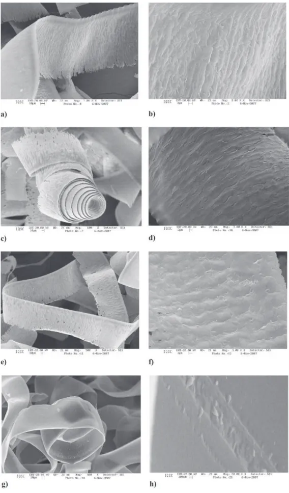
Fig. 6 Scanning electron microscopy images of the chips removed from the surface with different concentrations of CNT and the free surface of the chips showing the lamellar structure: (a) and (b) 0.02 wt % CNTs; (c) and (d) 0.07 wt % CNTs; (e) and (f) 0.3 wt % CNTs; (g) and (h) 0.4 wt % CNTs
the cross-sectional profile of the sample machined under a feed rate of 15 mm/rev (rough cutting condition) with 0.4 wt % CNTs. It can be seen that, even though a fine cutting condition is applied with a lower CNT concentration, the brittle mode is still present within the cutting grooves.
The results from the finishing cutting condition were also evaluated. Figures 4 and 5 present three-dimensional images and cross-sectional profiles of the samples respectively. In spite of the cutting con-ditions being fine, the machined surface still presents microcracks (Figs 4(a) to (c)). The machined surface with a higher concentration of CNTs (0.4 wt %) pre-serves the same trend as that shown in the roughing condition (Fig. 4(d)). The cross-sectional profile of the machined surface is also influenced by the for-mation of microcracks. The peak-to-valley value is also justified by the cross-section of the surfaces. The values are based on the waviness of the profile measured.
The cutting mode is clearly influenced by the concentration of CNTs in the epoxy matrix, even with low concentrations of CNTs. As the percentage of CNTs increases (above 0.3 wt %), ductile-mode machining takes place. CNTs are good thermal con-ductors, helping to eliminate heat from the cutting area, especially at higher concentrations (above the threshold).
3.2 Analyses of chips removed
Figure 6 presents SEM images of the lamellae formed along the chips (typically formed on the free surface of the chip, i.e. opposite the tool rake face). All chips shown were removed under the same cut-ting conditions (f ¼ 15 mm/rev, depth of cut ¼ 20 mm). It is interesting to observe that the chips removed from the samples with 0.07 and 0.3 wt % CNTs presented small holes in the surface. Although the surface has pits, all the chips presented a ribbon-like form, which is typical of the ductile-mode material removal mechanism (commonly observed in ductile metal), but the material behaves in a rather brittle manner – it chips. This lamellar struc-ture is a sign of shear deformation during chip for-mation. However, the microstructure of the chips removed from the sample with the largest con-centration of CNTs (0.4 wt %) did not present any signs of lamellar structure formation, as seen in Fig. 6(h) at 20 000 · magnification. This can also be seen in Fig. 2, which shows the surface finish along the cutting groove.
4 CONCLUSIONS
Results of diamond turning tests on carbon nanotube composites are presented. Samples with smaller quantities of CNTs (0.02 and 0.07 wt %) showed microcracks within the cutting grooves (perpendi-cular to the cutting direction). This indicates that the amount of CNTs in the epoxy matrix has a direct influence on the mechanical properties of these materials. The area average surface roughness (Sa) in
most tests is below 1 mm. The Savalues (also
influ-enced by the material removal mechanism) are 0.1980 mm up to 0.9595 mm for samples with the lower concentration of CNTs and the largest con-centration respectively. When the percolation threshold is largely overcome, the surface morphol-ogy is changed. This observation is important in order to minimize the quantity of CNTs added to modify the properties. It can be anticipated that other mate-rials such as silica (already adopted in tyres) could be used to modify the dynamics of the turning process. REFERENCES
1 Bachtold, A., Hadley, P., Nakanishi, T., and Dekker, C. Logic circuits with carbon nanotube transistors. Science, 2001, 294, 1317.
2 Hashimoto, A., Suenaga, K., Gloter, A., Urita, K., and Ijima, S. Direct evidence for atomic defects in graphene layers. Nature, 2004, 430, 870.
3 Ebbesen, T. W., Lezec, H. J., Hiura, H., Bennett, J. W., Ghaemi, H. F., and Thio, T. Electrical conductivity of individual carbon nanotubes. Nature, 1996, 382, 54. 4 Hone, J., Whitney, M., Piskoti, C., and Zettl, A. Phys.
Rev. B, 1999, 59, R2154.
5 Berber, S., Kwon, Y. K., and Tomanek, D. Unusually high thermal conductivity of carbon nanotubes. Phys.
Rev. Lett., 2000, 84, 4613.
6 Barrau, S., Demont, Ph., Peigney, A., Laurent, Ch., and Lacabane, C. Effect of palmitic acid on the electrical conductivity of carbon nanotubes–epoxy resin compo-sites. Macromolecules, 2003, 36, 5187.
7 Hussain, F., Hojjati, M., Okamoto, M., and Gorga, R. E. Polymer-matrix nanocomposites, processing, manu-facturing, and application: an overview. J. Composite
Mater., 2006, 40(17), 1511–1575.
8 Bassil, A., Puech, P., Bacsa, W., Pizani, P. S., Jasinevicius, R. G., Demont, Ph., Barrau, S., Lacabanne, C., Bacsa, R., and Flahaut, E. Laser induced modifications of carbon nanotube composite surfaces.
Jap. J. Appl. Phys., 2006, 45(10A), 7776–7779.
9 Carr, J. W. and Feger, C. Ultraprecision machining of polymers. Precision Engng, 1993, 15, 221–237.
10 Gubbels, G. P. H. Diamond turning of glassy polymers. PhD Thesis, Technische Universiteit Eindhoven, Eind-hoven, The Netherlands, 2006, 199 pp.