HAL Id: hal-00965542
https://hal.inria.fr/hal-00965542
Submitted on 25 Mar 2014
HAL is a multi-disciplinary open access
archive for the deposit and dissemination of sci-entific research documents, whether they are pub-lished or not. The documents may come from
L’archive ouverte pluridisciplinaire HAL, est destinée au dépôt et à la diffusion de documents scientifiques de niveau recherche, publiés ou non, émanant des établissements d’enseignement et de
A Framework for Variable Content Document
Generation with Multiple Actors
Abel Gómez, M. Carmen Penadés, José H. Canós, Marcos R. S. Borges,
Manuel Llavador
To cite this version:
Abel Gómez, M. Carmen Penadés, José H. Canós, Marcos R. S. Borges, Manuel Llavador. A
Framework for Variable Content Document Generation with Multiple Actors. Information and Soft-ware Technology, Elsevier, 2014, Special Sections from ”Asia-Pacific SoftSoft-ware Engineering Confer-ence (APSEC), 2012” and ” Software Product Line conferConfer-ence (SPLC), 2012”, 56 (9), pp.1101-1121. �10.1016/j.infsof.2013.12.006�. �hal-00965542�
A Framework for Variable Content Document
Generation with Multiple Actors
Abel Gómeza,∗, M. Carmen Penadésb, José H. Canósb, Marcos R. S.
Borgesc, Manuel Llavadord
a
AtlanMod, École des Mines de Nantes - INRIA - LINA 4 rue Alfred Kastler. 44307 Nantes, France
b ISSI-DSIC. Universitat Politècnica de València.
Cno. de Vera, s/n. 46022 Valencia. Spain
c Programa de Pós Graduação em Informática. Departamento de Ciência da
Computação. Instituto de Matemática. Universidade Federal do Rio De Janeiro. Brazil
d Instituto Tecnológico de Informática. Universitat Politècnica de València.
Cno. de Vera, s/n. 46022 Valencia. Spain
Abstract
Context: Advances in customization have highlighted the need for tools supporting variable content document management and generation in many domains. Current tools allow the generation of highly customized documents that are variable in both content and layout. However, most frameworks are technology-oriented, and their use requires advanced skills in implementation-related tools, which means their use by end users (i.e. document designers) is severely limited.
Objective: Starting from past and current trends for customized docu-ment authoring, our goal is to provide a docudocu-ment generation alternative in which variants are specified at a high level of abstraction and content reuse can be maximized in high variability scenarios.
Method: Based on our experience in Document Engineering, we iden-tified areas in the variable content document management and generation
∗Corresponding author. Address: AtlanMod, École des Mines de Nantes. 4 rue Alfred
Kastler. 44307 Nantes, France. Tel: +33 2 51 85 82 39
Email addresses: [email protected] (Abel Gómez),
[email protected](M. Carmen Penadés), [email protected] (José H. Canós),
[email protected](Marcos R. S. Borges), [email protected] (Manuel
field open to further improvement. We first classified the primary sources of variability in document composition processes and then developed a method-ology, which we called DPL – based on Software Product Lines principles – to support document generation in high variability scenarios.
Results: In order to validate the applicability of our methodology we implemented a tool – DPLfw – to carry out DPL processes. After using this in different scenarios, we compared our proposal with other state-of-the-art tools for variable content document management and generation.
Conclusion: The DPLfw showed a good capacity for the automatic gen-eration of variable content documents equal to or in some cases surpassing other currently available approaches. To the best of our knowledge, DPLfw is the only framework that combines variable content and document work-flow facilities, easing the generation of variable content documents in which multiple actors play different roles.
Keywords: Variable Data Printing, Document Product Line, Feature Modeling, Model Driven Engineering, DITA, Document Workflow, Organizational Modeling, Document Generation
1. Introduction
Managing variable content documents is a key aspect in domains such as e-learning, e-commerce, e-government and software development. The main challenges in generating customized manuals, contracts and governmental documents, among others, are the processes that involve defining document variants and content reuse [1, 2]. Although the documents usually follow a standard structure, they include some sections that can be repeated across different documents and others that are specific to a particular case. Al-though supporting variable content makes document generation more effi-cient it requires methods of specifying and handling variations.
In the Document Engineering field the problem of generating customized documents is known as Variable Data Printing (VDP). Increasingly sophis-ticated approaches to VDP have been proposed in recent decades, ranging from personalized letters in the Mail Merge [3] style, to customized multime-dia documents [1, 2, 4, 5, 6]. Traditional approaches dealt with variability by including form fields in the documents, so that user-provided values become part of the document. More recent approaches have gone beyond variable data to support variability in document contents, but most of them require
document designers to be experts in XML and associated technologies such as XSLT (e.g. the Document Description Framework, DDF [1]), which they frequently lack. The challenge is then to provide a powerful document gen-eration alternative that hides the complexity intrinsic to high variability sce-narios. It is therefore a natural solution to develop end-user tools that move the definition of variability closer to the problem domain, to give users the op-tion of distinguishing between the fixed and variable parts of the document, regardless of the final document format.
However, disguising the technical complexity is not the only problem to be solved. Document generation processes are complex activities that involve different participants, each with different tasks and different access rights to certain parts of the document. A description of the actors, responsibilities and access rights within a document generation process (generally known as the specification of the Document Workflow ) is therefore required. Sup-port for document workflow definition and enactment is mandatory for any tool aiming at providing organization-level document generation and man-agement. Instead of isolated editing actions requiring manual synchroniza-tion to produce a final document, document workflow-enabled environments provide uniformity and global management of document creation processes. To sum up, end-user orientation must be a distinguishing feature of VDP tools. This means that (i) the entities handled with the tools must be close to the problem domain, and (ii) some methodological guidance supporting the specification of both the document content and the document workflow should be provided.
The Document Product Lines (DPL) approach [7] provides a framework for variable content document generation that follows an alternate path to the traditional variable document generation. DPL was created with a twofold goal: first, to make creating variable content documents available to non-experts by including a domain engineering process previous to the document generation itself; and secondly, to enforce content reuse at domain level. Both goals can be achieved under the principles of Software Product Line Engineering (SPLE). The key to the success of a DPL process lies in the definition of the variability model, which describes how documents can vary (the so-called feature models), and in the existence of an organized collec-tion of document components (core assets). The document components are pieces of content that can be combined to produce the final document us-ing a customized document editor generated by the product line and which implements the document workflow.
In [8] we introduced DPLfw, a DPL implementation based on Model Driven Engineering (MDE) principles [9]. DPLfw supports all DPL pro-cesses and has been applied in different domains such as generating Emer-gency Plans [8] and technical documentation [10]. In this paper we extend the description given in [8] to (i) include validation mechanisms, (ii) add or-ganizational and workflow modeling capabilities, and (iii) provide workflow enactment capabilities by using custom document editors built at runtime. All these features are illustrated in a complete and comprehensive example, and the incorporated improvements are shown by comparing our approach with other variable content frameworks.
This paper is organized as follows. Section 2 presents the different types of variable content scenarios. Section 3 introduces DPL, showing how SPLE techniques have been adapted to support variability-driven document gen-eration. Section 4 introduces the DPLfw framework. Section 5 describes in detail the different components of the DPLfw framework, shows how they work by giving a practical example. Section 6 summarizes the main contributions of our proposal, and provides a comparison with other variable content document generation frameworks. Finally, Section 7 closes the paper by presenting our conclusions and outlining future work.
2. Motivation
Customization has been a recurrent issue in the Document Engineering field for decades. From the early SGML times until the highly customizable documents generated with the newest tools, a number of issues have been addressed by researchers and practitioners. In this section, we provide ex-amples of different types of variable content scenarios. These exex-amples will help us to put our work in context and clarify our present contribution to the field.
Example 1 (Presentation) The publisher of a bestselling author has a publishing policy that includes the generation of different quality editions of a given book. Initially, a luxury edition is produced, followed weeks later by a hard cover version, which is in turn followed by a pocket edition at a much lower price. For each edition, a different design (i.e. page layout, font, il-lustrations, etc.) must be applied to the original text. If possible, automatic procedures should be used to generate the different versions.
This is perhaps the very first case of variable content scenario and its solu-tion has also been in place for a long time. The early markup languages such as SGML [11] prescribed the separation of content and layout in structured documents, using tags to delimit relevant content sections and style sheets to define sets of presentation instructions for different versions of the same content. The invention of the Web and HTML, a derivative of SGML, made markup languages very popular. Style sheets came to the Web later, when website designers realized that they had to fully rewrite the HTML code of their Web resources every time a site was restyled. Further developments led to the XML language and to XSL, the eXtensible Stylesheet Language as the framework supporting multiple views of structured documents. 2
Example 2 (Variable data printing) A large travel agency wants to ad-vertise its new summer campaign. In order to increase customer satisfaction, they want to launch a new utility called “myAgent” that provides customized offers based on customer information. The offer is simply a document that includes personal customer data, plus a number of elements selected from a repository using as retrieval criteria a customer profile based on previous in-teractions with the system. With this type of service the agent hopes to avoid providing customers with information outside their scope of interest.
This example (inspired by [1]) is a generalization of the classical Variable Data Printing (VDP) problem. Among the first systems supporting VDP, the Mail Merge utility allowed the design of document templates that included placeholders for parts of the document content. Batch processes were then launched in which different copies of the template were generated in such a way that placeholders were replaced by actual values from a database. Business companies were then able to generate customized documents such as the examples given above, as well as employee business cards and any type of document that took values from data sources. Different extensions of the basic model have been developed in recent decades. One of the latest solutions, the DDF [1], defined an XML based language for the specification of variable content based not only on database queries but on any expression that could even include some parts of the document located by means of XPATH expressions. As one may expect, recent VDP tools are based on
XML and hence also support the variability in presentation described in Example 1. 2
Example 3 (Document families) The Spanish Civil Defense Authority issued regulations to oblige different types of organizations to be prepared for emergencies. These required that every public service organization must draw up an emergency plan that includes all the relevant information from preparedness to response. The basic content and structure of the emergency plan is provided in the form of a table of contents, and this basic plan struc-ture works for most organizations. However, in some cases additional content must be included, such as in the case of nuclear plants, where the basic plan must be accompanied by an evacuation plan for all locations less than 30 km away. In many cases parts of the plan content (like standard response pro-cedures, or technical information on fire extinguishers) will be common to more than one organization. The aim of the Authority is to provide a tool able to automatically generate a customized emergency plan template from the characterization of a given organization. This template will reuse as much content as possible from previously developed plans, thus saving time and money.
The idea of entities sharing common features while differing in others is not exclusive to document engineering. As a matter of fact, the notion of product family had appeared much earlier in other fields. Particularly rele-vant in the case of software development, the term program family was coined by Parnas [12] and later included in the notion of Software Product Line [13]. The essence of Software Product Line Engineering is to model a family of software artifacts using a language able to distinguish commonalities and differences in the members of the family. From the variability specification and using components from a repository it is possible to achieve significant reductions in development time and high reuse ratios in some domains.
The product line approach looks very promising for the development of families of documents in cases with high content variability. Other domains in which a product line approach to customized document generation is useful are e-government, e-learning and, in general, domains with extensive content variability and reuse. 2
Example 4 (Technology Variability) A food website has a large collec-tion of recipes after years of collecting and organizing informacollec-tion. To gain an advantage over its competitors the web owners want to make recipe down-loading more flexible at different levels. Firstly, by allowing users to get customized recipes for a given dish using their own ingredients (to avoid un-available ingredients). Secondly, by providing different type content for a given cooking step according to the user’s abilities. For instance, the instruc-tions for preparing a bolognese sauce can be provided in a video for beginners and in texts of varying complexity for average and expert cooks.
This case illustrates what we call technological variability and is a variant of the scenarios described in Examples 1 and 3. A specific part of a document can be “filled” with different types of content, which can be selected by the user when configuring a specific member of a document family. This type of customization is one of the features of the DPL approach, as will be seen in Section 6. 2
Example 5 (Multi-actor editing processes) A software development com-pany wants to increase the efficiency of the development of the technical doc-umentation associated with its products. One of their major concerns is the management of document variants when the parts of the products change. To cope with this, they plan to follow a product line approach, as described in Examples 3 and 4. However, there is an additional requirement: the prod-uct line must comply with the company’s document workflows. A document workflow model is the specification of the process followed in the development of a document. The process is described in terms of the activities performed, the control and data flow between these activities, and the actors performing them. In general, technical documentation development is performed by a hi-erarchical organization in which (parts of ) the document contents are drawn up by editors and later approved by someone else. This is an important step in guaranteeing the quality of the generated document.
In a product line environment, the document workflow cannot be defined in advance, since it is dependent on the parts of the content selected for a given member of the document family. The classical product line approaches must therefore be extended to include document workflow management.
A document workflow definition mechanism is the key to obtaining end-user oriented tools. From the experience gathered during decades of Workflow Management Technology, graph-based languages are those best suited to making process-oriented specifications [14, 15]. In the case of document workflows, each node in the graph will typically represent an editing action that must be performed by some actor at some point in the process. By editing action we mean either providing or modifying content, as well as approving or rejecting a particular content. For instance, different parts of a software manual may be written and approved by different members of the company. Similarly, the evacuation procedures in an emergency plan can be designed by specialized safety engineers and approved by civil defense agencies before their release; or in a typical e-learning scenario, document workflow consists of a teacher compiling an exam taken by a student and corrected by a third person. 2
Examples 1 to 5 illustrate the different ways of understanding customiza-tion in document generacustomiza-tion. As the first conclusion, we believe that dealing with variable content documents is a complex task and is difficult to solve at a low abstraction level. Product line approaches provide methodologi-cal support to help document engineers follow systematic processes, starting with explicit variability modeling and automating generation and enforcing reuse. Our second conclusion is that handling large collections of reusable content requires tool support. In the following sections, we introduce DPL, our methodological approach to variable content document generation, and its supporting tool, DPLfw. The above examples also serve to define the framework we use to compare DPLfw with other variable content support tools.
3. Document Product Lines
DPL aims to apply SPLE principles, techniques and tools to the gen-eration of variable content documents involving multiple participants. DPL provides methodological guidelines to model the commonality and variability in a document family as a set of features. Such document features are as-signed to the different actors that play different roles. A document workflow model is generated from the features selected for a specific document. The workflow model describes the tasks that each user must carry out to obtain the final document. To achieve this, different custom document editors (tar-geted at a specific user) are generated (re)using components and following a
D oc u m e n t Produ c t L in e D o m a in E ng ine e ring A p p lic a tio n E ng ine e ring Analyse Document Family Design Document Family Develop Core Assets Generate Document Line Production Plan Document Feature Model Reference Architecture Core Assets Characterize Document Retrieve Core Assets Generate Document Creation’s Workflow Enact Document Creation’s Workflow Document Document Feature Model Configuration Selected Core Assets Workflow Model Customize Document Creation’s Workflow Custom Document Editors Organizational Model
Figure 1: DPL-based Document Generation Process
product line approach. These editors implement the views of each actor in the workflow of creating the document, acting in a way similar to a wizard. The enactment of the workflow (i.e., execution by the editors) produces spe-cific instances of the variable content document that will later be composed with a layout to generate a final version of the document. An outline of the DPL method is given in the remainder of this section.
The starting point of a DPL process is the identification of variability sources in documents from a domain-oriented perspective [16, 17]. To achieve this we adapted classical feature models [18] to the document generation do-main. In this way we obtained an expressive method of defining variability and can take advantage of tools for analyzing such models [19, 20]. The adap-tation was carried out bearing in mind the specific requirements of variable content documents.
Figure 1 summarizes the DPL document generation process. The process is described using the Business Process Modeling Notation (BPMN) [21]. Only the main tasks and artifacts are depicted for the sake of simplicity. Start and end events are represented by circles, data objects are shown as a sheet of paper, tasks by rounded boxes, sequence flows are shown as solid lines, message flows by broken lines and data associations are dotted lines. As in SPLE, the DPL process includes two iterative subprocesses. The first, called Domain Engineering, takes an organizational model as input and is composed of four tasks. In the Analyse Document Family task, a domain
engineer specifies the documents in terms of content and technology. The domain engineer must also identify the actors who contribute to the docu-ment and their specific responsibilities. These contributors are the members of the organization in which the DPL methodology is applied, and should be properly described in an organizational model. Since the organizational modeling stage is considered outside the scope of the DPL methodology, the organizational model is assumed to pre-exist. The result of the analysis is a document feature model including mandatory, optional and alternative fea-tures of both OR and XOR variants. Mandatory feafea-tures are the parts that must be included in all the documents of the family, whereas the optional and alternative feature will only be included in certain members of the family. In the Design Document Family task, the generic document architecture is defined by identifying the document components (related to the content) and software components (related to content-supporting technology) required, ac-cording to the feature model built in the previous stage. Specific instances of the architecture are created later in the process, after the variability points for a specific document have been fixed.
DPL assumes the existence of a Repository where document and software components are stored and organized for reuse. They are the core assets in SPLE terminology. Metadata are attached to each core asset in order to support asset retrieval processes in the Develop Core Asset task to find existing components. If a requirement specified in the feature model cannot be fulfilled by any core asset in the repository, a new component should either be developed or retrieved from other repositories. In this case, a library of applications to create and/or modify core assets must be available. Finally, in the Generate Document Line task, a production plan is obtained. This is a process that specifies how the components are integrated according to the different relationships defined between the document features.
The second subprocess, called Application Engineering, supports the gen-eration of the variable content documents by the collaboration of different actors. In the Characterize Document task, the document engineer (the per-son in charge of coordinating the creation of a specific document) selects the variability points, i.e. the optional and alternative features included in the document. This task includes the selection of both content and technology features. Next, the core assets are sought according to the variability spec-ification made; and, in the Generate Document Creation’s Workflow task, the assets are used to generate a Workflow Model which clearly defines how the document must be edited and completed by the different actors. This
workflow model can be customized by the document engineer, rearranging tasks and tuning actor responsibilities. The assets linked to the editing tasks include both the software components required to edit or to generate the final document and the document content components which pre-populate the editor’s contents. These assets are used to generate the custom editors that represent a user-centered view of the document workflow. Finally, in the Enact Document Creation’s Workflow task, the editors are used to complete, if necessary, the final content of the document. By final we mean that it will not contain any variable data since all the document components will have been instantiated and approved during the editing.
4. The DPLfw Framework
DPLfw provides the methodological and technological background to creating variable content documents by the DPL approach. DPLfw was developed following the MDE and Model Driven Architecture (MDA) [22] paradigms, which allowed us to take advantage of code generation techniques for the implementation of a tool prototype.
DPLfw was also designed to be extensible and highly configurable, al-lowing any new technology or platform to be plugged in. This requirement made us to choose Eclipse [23], one of the state-of-the-art development en-vironments, for its creation. Three key technologies were selected for its implementation: the Equinox framework [24], the Eclipse Modeling Frame-work (EMF) [25, 26] and the Connected Data Objects (CDO) frameFrame-work [27]. The first is an implementation of the OSGi standard [28], a dynamic component model and a service platform to build modular and extensible Java applications, which provides the basic runtime services for the Eclipse IDE itself. The second (EMF) is a framework to build applications using MDE techniques, raising the level of abstraction and reducing development time by using code generators. The third (CDO) is a framework built on top of EMF which allows concurrent and transactional modifications of dis-tributed EMF models. CDO provides authentication, storage and retrieval mechanisms, regardless of the actual database management system used (the current version of DPLfw uses PostgreSQL [29] as its persistence back-end). In some preliminary works [7, 30] we used the well-known pure::variants tool [31] to validate the DPL proposal. However, developing a full-featured framework to support DPL allows us to focus on the Document Engineering field and especially to incorporate our own feature metamodel tailored to its
DPLFW Application Engineering Organization Modeling Domain Engineering Validation Module ? Domain Engineer Feature definition Document component definition Feature editor Configuration editor Workflow editor Custom Document Editors Document Generator Final Document Document Component Repository Credentials Manager Organization editor Organization Manager Document Engineer Component Editor Feature Selection Data input Users Figure 2: DPLfw overview
sources of variability, thus simplifying the complexities of generic SPL tools. This is demonstrated in the first fully functional Eclipse-based version of DPLfw, which was presented in [8]. However, this first version had two lim-itations; firstly, it only supported fully instantiated document components, whereas in practice things are somewhat more complicated. Some document components can only be partially instantiated, as in the case of templates, or form-based parts, which must be completed by the final users (the vari-able data). Secondly, no support for multiple actors was provided. However, the current version of DPLfw supports multiple actors, custom document editors and model validation.
The DPLfw is made up of a set of pluggable components – namely edi-tors, viewers and explorers – which follow the Rich Client Platform [32] archi-tecture. The implemented functionality facilitates exploring different repos-itories, defining organizations, creating new document components, defining document templates as feature models, tuning document workflow models, creating and displaying custom editors and generating documents. These ele-ments communicate with a components repository and a credentials manager in a client-server architecture. In the remainder of this section we outline the main elements of DPLfw and how they communicate with each other.
Figure 2 describes how a fully-fledged DPL process is carried out in DPLfw. The Domain Engineering stage is an iterative process. For the sake of simplicity no specific order is enforced to execute its tasks as far as there is a fully populated document feature model describing the domain at the end of the stage. The Feature Editor is used by the Domain Engineer to
characterize the variability of the domain as a document feature model (as described in the Analyse Document Family task of the DPL process). The Feature Editor is closely related to three components. First, the Credentials Manager is a directory service which stores information about the members of an organization (users, groups, hierachy, login credentials, etc.). The or-ganization’s information can be edited by the Organization Manager using the Organization Editor. Secondly, the FaMa framework [33] is a valida-tion and verificavalida-tion engine which uses formal representavalida-tions to guarantee that the feature models defined in DPLfw have no errors. And thirdly, the Repository contains the core assets (document components) that will later be reused. All these elements support the Analyse Document Family task (cf. Figure 1). For the sake of simplicity, the Reference Architecture matches the structure of the feature model, and thus, the Design Document Family task is implicit and does not require user-interaction. The Component Editor supports the Develop Core Assets task and is used to create new document components and add them to the Repository. The Generate Document Line, which will describe how to retrieve and integrate the different components to obtain the final product, is also implicit: DPLfw implements automatic generation of the default production plan, since the structure of the docu-ment family is determined by the docudocu-ment feature model, every content component has a default handler (called Disseminator, see Section 5.3), and there exist predefined mechanisms to retrieve the different components from their corresponding repositories.
The remaining elements are related to the Application Engineering sub-process. The Configuration Editor supports the Characterize Document task through the selection of variability points. The Document Engineer is as-sisted in the configuration process by means of the Validation Module, avoid-ing configuration errors. Once a document feature model configuration is defined, DPLfw Retrieves the Core Assets of the selected features from the repository and Generates a Document Creation Workflow model automati-cally. This model contains explicit information about the tasks and the actors involved. These tasks are inferred from the domain specification made in the feature model, and can be fine-tuned using the Workflow Editor – as the Customize Document Creation’s Workflow task specifies. Once a document workflow model is specified, the Enact Document Creation’s Workflow task starts and the Custom Document Editors are generated by composing the document components. These editors present actor-specific views of the doc-ument based on the permission given to each participant in the docdoc-ument
workflow. These editors are in charge of controlling user privileges with re-gard to document content and are used to fill in any remaining variable data. Finally, the Document Generator integrates the different components to ob-tain a fully instantiated document generated in a specific format (printed, hypermedia, etc.).
5. A closer look at DPLfw
In this section we present a detailed description of all the components that were introduced in Section 4. For each component we give a detailed description of its design and implementation as well as a practical example of how it is used.
Our practical example is a software development organization which uses DPLfw and aims to generate customized software manuals targeted at dif-ferent types of user. This organization is in charge of developing the DPLfw tool itself, and aims to use it to generate end-user manuals. The members of the organization (programmers, testers, managers, etc.) are grouped in different units: Analysis & Design, Implementation, Testing, Deployment, Documentation and Project Management. This organization has decided that the software manual of the DPLfw may be divided into four chapters, namely Introduction, Installation, First Steps, and Version History. How-ever, they have detected that the contents of these chapters depend on two different factors: (i) the type of user and (ii) the DPLfw version for which the manual is generated. They have therefore decided to use the DPLfw to develop a family of software manuals.
5.1. The Organization and the Credentials Manager
Following classical workflow models, the different actors involved in the document generation process are specified according to an organizational model. Although the organization modeling stage is not considered as a part of a DPL process, as explained in Section 3, DPLfw requires a generic model which enables interoperability with existing organizational models.
Figure 3 shows the organizational model defined in DPLfw. It describes an organization as a hierarchy of actors. Actors may be individuals (users) or groups of users called units (e.g. departments). The users may belong to one or more units, and units may be composed of other units. Every unit is managed by one user. Actors are identified by a universally unique identifier (UUID), must have a name, and may have a description and an e-mail address
Organization Actor uuid : UUID name : EString description : EString email : EString createUUID() Unit User login : EString hash : EByteArray salt : EByteArray disabled : EBoolean isValidPassword(EString) : EBoolean setPassword(EString) units 1..* users 1..* users 1..* manager 1 hasUnits 0..* belongsTo 0..1 belongsTo 1..* manages 0..*
Figure 3: Organizational Model
(in the case of units, the e-mail address corresponds to a mailing list including the addresses of all the members). For users, the login information is also stored, i.e., a unique login alias, a (randomly salted) hashed password, and a disabled status flag.
DPLfw provides out-of-the-box support for simple organizational models which comply with this specification. They can be edited using the Orga-nization Editor and may be stored either locally or remotely, following a client-server architecture. However, according to the idea that organiza-tional modeling is not part of the DPL methodology, DPLfw can use any existing organizational model by means of the Credentials Manager service. Thanks to this service, the actual persistence format and location of the or-ganizational models are transparent to the remaining DPLfw modules. The Credentials Manager provides an API to access different organization direc-tory managers, whether they are built-in or the external (such as LDAP). Example 6 In our sample scenario, a software development organization produces customized manuals for its software products. The structure of this organization is shown in Figure 4, which shows what the organizational model editor looks like. In the screenshot users are grouped into the following units: Analysis & Design, Implementation, Testing, Deployment – which in turn in-cludes a Documentation unit – and Project Management. Moreover, the De-ployment unit is formed by Analyst 1, DeDe-ployment Architect (who is also the
manager of the Unit), Documentation Manager, Programmer 1 and Tester 1.
Figure 4: Organization Editor
5.2. The Repository
The automation of document generation processes relies heavily on the availability of the components that will be reused to build the different doc-uments of the family. Such availability is granted by the Repository, which provides services for managing (i.e. creating, deleting and updating) and retrieving components (via e.g. keyword-based search). Additional services could be defined if required. We will now focus on document components (content components) for purposes of clarity.
The actual services provided by the Repository depend largely on the structure of the document components. In DPL, the document components of the Repository are called the InfoElements [7]. We modeled the Repository structure as shown in Figure 5: it is placed in a given location represented by a Uniform Resource Identifier (URI) [34] and may contain any number of Re-sourceNodes. These are elements which allow InfoElements to be organized
id : EString title : EString author : EString dateCreation : EDate dateInsertion : EDate description : EString keywords : EString language : ISO_Language publisher : EString InfoElement id : EString title : EString author : EString dateCreation : EDate dateInsertion : EDate description : EString keywords : EString language : ISO_Language publisher : EString contents : EString TextIE
contents : EString displayWidth : EInt displayHeight : EInt contents : EByteArray ImageIE displayWidth : EInt displayHeight : EInt contents : EByteArray contents : EString LinkIE contents : EString
asDita(EString) : Document throws ParserConfigurationException DitaRepresentable
asDita(EString) : Document throws ParserConfigurationException
latitude : EFloat longitude : EFloat LocationIE latitude : EFloat longitude : EFloat location : URI addInfoElement(InfoElement,Resource) deleteInfoElement(InfoElement) search(Query) : InfoElement Repository location : URI addInfoElement(InfoElement,Resource) deleteInfoElement(InfoElement) search(Query) : InfoElement name : EString ResourceNode name : EString
ResourceFolder Resource infoElements 0..* nodes
0..*
nodes 1..*
Figure 5: Repository Model
hierarchically. Two kinds of ResourceNodes can be defined: ResourceFolders, which may contain other ResourceNodes; and Resources, which contain the aforementioned InfoElements only. A Repository must also provide services for adding, removing and retrieving InfoElements, which are composed of two main blocks: data and metadata. The former is an encoding of the actual component content, be it text, image, or any other multimedia object. The latter is concerned with providing the information needed to describe and manage the content.
The set of attributes of the InfoElement class define the metadata schema used in DPL. Table 1 lists the metadata fields associated with InfoElements. We have selected a representative subset of the metadata elements defined in the Dublin Core Metadata Set [35]. The “Definition” column describes in a few words the meaning of the corresponding metadata “Element”. “Multi-plicity” indicates the maximum and minimum occurrences of each element in a metadata record. As can be seen in Table 1, InfoElements also have a type. For the sake of simplicity, in the current DPLfw version, types are im-plemented by inheritance. For instance, Figure 5 shows some different types of InfoElements, such as text (TextIE ), link (LinkIE ), image (ImageIE ) and geographical coordinates (LocationIE ).
main-Table 1: Repository metadata
Element Definition Multiplicity
Author(s) Person/entity responsible of the InfoElement 1..*
Date of Creation Date the InfoElement was created 0..1
Date of Insertion Date the InfoElement was added to the repository 1
Description An account of the InfoElement 0..1
Identifier A unique identifier of the InfoElement in the
reposi-tory
1
Subject The main topic of the InfoElement 0..*
Keywords Other topics of the InfoElement 0..*
Language Language of the InfoElement 0..1
Publisher Person/entity who distributes the InfoElement 0..1
Title A name given to the InfoElement 1
Type The nature or genre of the InfoElement 1
tain backwards compatibility with previous work [7, 30] and allows the use of automated tools for document generation, since InfoElements are represented and managed using the DITA standard [36]. DITA is an XML framework for the production of topic-oriented documentation. The main element of the DITA specification is the topic. DITA topics are organized into different hierarchies for different output documents, or DITA maps. In DPLfw an InfoElement is represented as a DITA topic.
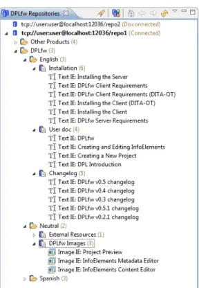
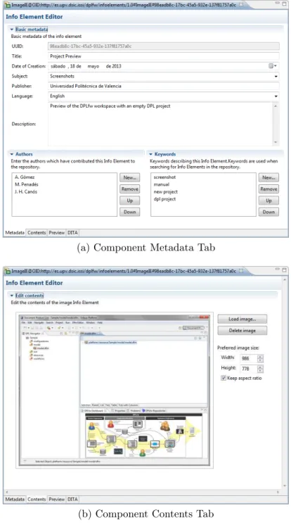
Example 7 Figures 6 and 7 show the user interfaces of the DPLfw com-ponents used to manage and develop the core assets. These screenshots show how to add new contents to a specific repository, in this case, components of the DPLfw manual. Figure 6 shows the Repository Explorer, which allows connecting to different repositories. Contents in repositories are organized hierarchically as described in Figure 5. When a specific repository is selected, users can add/edit/remove any content in it. New disseminators for different content types can easily be added to DPLfw following the OSGi architecture. Figure 7 shows how a new document fragment, an image InfoElement called Project Preview, is edited. Figure 7a shows the component metadata tab, and Figure 7b shows the content tab. The former is used to define the In-foElement’s metadata and the latter is used to assign the content to the new document component. In this example, an image editor is used to select an image file. Other types of editors may be used to deal with other types of content (such as text).
(a) Component Metadata Tab
(b) Component Contents Tab Figure 7: Component Editor
5.3. The Feature Editor
In line with the rest of the Document Engineering community, we define a document as the union of two components: content and presentation. The document content includes a template that defines the logical structure of the document, plus the components that instantiate the template. The presenta-tion includes the layout that defines exactly where each piece of content is to be placed and also how the piece will appear in the document. The latter is important because a given component may be shown in different ways. For instance, tax statements include some mandatory sections along with others that only apply to specific cases (content variability). Additionally, specific sections of a tax statement can be presented in different forms (parts of the tax statement can be produced as a printed document, keeping others only as a set of electronic forms). This technology dimension is relevant in the DPL process, since the specification of variability in a document family is done in terms of both content and technology.
To cope with both sources of variability, DPL can handle two different types of features: those related to document content (ContentDocument-Feature or CDF) and those related to the technology used to represent the content (TechnologyDocumentFeature or TDF). A CDF represents a part of the document and can be associated with one or more TDFs. As in clas-sical feature models, cross-tree relationships may link document features in DPL variability models, such as the “requires” and the “excludes” constraints. These constraints may be checked in subsequent development stages to en-sure consistency in selecting features.
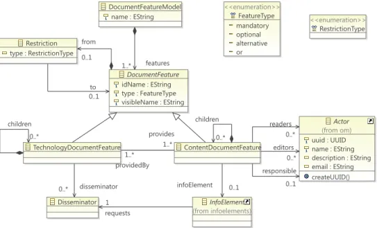
The Feature Editor enables Document Feature Models to be defined. Fig-ure 8 shows the featFig-ure metamodel supported by DPLfw and how it has been adapted to deal with multiple actors. We used pure::variants [31] as a ref-erence in developing this metamodel, since it is widely known and used by the SPLE community. In DPLfw, a DocumentFeatureModel is composed of a set of DocumentFeature elements, which, as explained in Section 3, can be related to either content (ContentDocumentFeature) or technology (Techno-logyDocumentFeature). A DocumentFeature can be declared as mandatory, optional, alternative (XOR group) or optionally selectable (OR group). Com-plex Restrictions (requires, excludes or logical combinations of these) may be defined between two or more features.
The ability to define different types of relationships and restrictions among features may bring great complexity into DPLfw feature models. In this context, due to the nature of feature models, the use of logic representations
DocumentFeatureModel name : EString DocumentFeature idName : EString type : FeatureType visibleName : EString ContentDocumentFeature TechnologyDocumentFeature <<enumeration>> FeatureType mandatory optional alternative or <<enumeration>> RestrictionType InfoElement (from infoelements) Restriction type : RestrictionType Disseminator Actor (from om) uuid : UUID name : EString description : EString email : EString createUUID() features 1..* children 0..* providedBy 1..* children 0..* provides 1..* infoElement 0..1 from 0..1 to 0..1 requests 1 disseminator 0..* readers 0..* editors 0..* responsible 0..1
Figure 8: Feature metamodel
and languages can help in the development of model checkers. In line with this idea, the Feature Editor relies on FaMa [33], a framework which ful-fills our requirements to detect and avoid errors in the definition of feature models. FaMa was integrated as a new module in DPLfw and its use is transparent to the user, hiding the complexities of the underlying formalism – Constraint Satisfaction Problems (CSP) [37] in the case of DPLfw. Using FaMa, DPLfw is able to detect different types of error (void feature mod-els, dead features, false-mandatory features, etc. [38]) and provide detailed messages to help fix them easily. Actual document content is associated with content document features via instances of the InfoElement class.
In order to link actors with editing tasks, we have merged the organi-zational model with the DPL document feature metamodel (only the class involved, i.e. Actor, is represented for purposes of clarity). Both models are connected via three associations between the CDF and Actor classes. The instances of the Actor class will contribute to complete the InfoElement associated with the CDF with different roles: as an editor, an actor has read/write permissions; as a reader, he/she has only read permission; and, as the person responsible, he/she is responsible for approving the content. Only actors granted with one or more of these authorizations can access the
InfoElement associated with a CDF. The 0..n multiplicity in the Actor ends of the associations means that some CDFs can be non-editable, non-readable and/or do not require approval.
Finally, according to [39], a Disseminator represents a software compo-nent used to visualize different types of InfoElements. Examples of dissemi-nators are text editors, image viewers, video players, and web services.
A document family is an instance of the above metamodel. The elements that compose this instance drive the definition of the architecture of the associated document editors that will be generated in the product line. Example 8 As specified above, the DPLfw software manual may be struc-tured in four chapters: Introduction, Installation, First Steps, and Version History. The structure and contents of the final document depend on two factors: (i) the type of user at which the manual is targeted, and (ii) the DPLfw version for which the manual is generated.
We defined the feature model shown in Figure 9 bearing in mind these two sources of variability. The model specifies the family of documents to be generated as a set of features. An exclamation mark denotes mandatory features, a question mark optional features, a double-headed arrow alternative features and a cross is the symbol for OR groups. The model contains four top-level CDFs – one for each of the chapters mentioned above – and one top-level TDF – which defines the type of manual.
The first CDF ( Introduction) is composed of one mandatory feature and two alternative features. The first represents the version of the DPLfw for which the manual will be generated and contains five alternative chil-dren features (from Version 0.2.1 to Version 0.5.1). The other two alter-native features are the two different types of user at which the manual is targeted: system administrators (those in charge of installing and configur-ing the framework in a given organization) and end users (those who will use the tool to carry out DPL processes). The Introduction sub-features cover the two sources of variability we identified in the domain: version number and type of user. Since variations in the content of the document should depend on these factors, we introduced a set of restrictions (“requires” rela-tionships). For example, a manual for system administrators must include general installation instructions, server instructions (the client does not need administrative rights to be installed), and the version history. A final users’ manual only requires the first steps section. In both cases additional sections
may also be included, unless another restriction is violated.
The second top-level CDF, Installation, has two mandatory sub-features: Requirements and Installation Steps. The former represents the software that must be installed and configured prior to installation of DPLfw com-ponents, while the latter describes the detailed steps to set-up an executable DPLfw environment. These two sub-features can be differentiated for both the server and the client part of the framework, i.e., Server Requirements, Client Requirements, Server Installation and Client Installation. Prior to DPLfw version 0.5, the DITA Open Toolkit was required to be installed and configured as an external program; but in current versions of the framework a minimal runtime has been embedded in DPLfw itself. The features DITA Open Toolkit and DITA Open Toolkit Install are therefore optional. We also included some “requires” and “excludes” relationships to illustrate how DPLfw can manage different types of restrictions. The “requires” relation-ships lay down that if one of these sections is included, the other must be included too, and the “excludes” relationships state that no information about installing DITA must be included in the manual for the latest versions (i.e. v0.5.0 and v0.5.1). Additionally, the Installation feature has an optional sub-feature: Installation Screencast. Since this sub-feature represents a video, it requires a multimedia manual (represented by a TDF).
First steps is the third top-level CDF. It represents the sections of the manual which give instructions on how to begin to work with the tool. Tasks such as Creating a New Project or Creating and Editing Infoelements are covered in this part of the document. The optional children features ( Project Preview and InfoElements Editor Preview) are contents that may enrich the document by showing screenshots.
The last CDF is the Version History, which contains a list of the bugs that have been solved in every release, together with new enhancements included in the different versions of the framework.
As explained above, CDFs may be associated with actors. The actors’ responsibilities/authorizations are set while the document feature model is built. As an example, we have defined the following authorizations in the sample scenario:
• All the members of the organization have read permissions for the entire document.
• The Introduction CDF (and all sub-features) may be editable by the Documentation unit.
• The Installation CDF (and all sub-features) may be editable by the Deployment unit.
• The First Steps CDF will be unmodifiable. Its direct children will be editable by the Documentation unit, and the Project Preview and the InfoElements Editor Preview CDFs may be editable by both the Docu-mentation and the ImpleDocu-mentation units.
• The Version History will be editable by the Implementation unit. • The Version History contents must be approved by Programmer 1 (the
manager of the Implementation unit).
• The contents of all the remaining editable CDFs must be approved by the Documentation Manager.
Finally, we modeled the TDF to cope with the diversity of formats in which the CDFs can be represented. In this case study, the DPLfw manual may be printed (for instance, a PDF file) or multimedia (an HTML web page with embedded video content). These options are modeled as alternative TDFs in Figure 9.
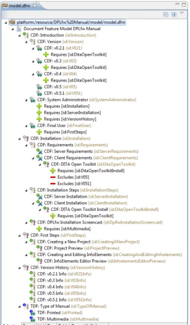
To illustrate the validation capabilities provided by FaMa, Figure 10 shows a modified version of the document feature model together with the Problems view. There, we can see that an additional requirement has been added: the alternative feature v0.5 needs to have the DITA Open Toolkit (ID: DitaOpenToolkit) feature, as do Versions 0.2.1, 0.3 and 0.4. However, this restriction involves an error: the feature v0.5 (ID: V05) is a dead feature, i.e. it cannot be present in any possible product because it collides with the DITA Open Toolkit feature, which has an exclusion restriction. All these kinds of semantic errors, even if the feature model is void (i.e. there is no valid configuration possible), are automatically detected and reported to the user using the Problems view.
Figure 10: Feature Editor and Problems View
5.4. The Configuration Editor
Configurations are defined with the Configuration Editor, which guides users through the first task of the Application Engineering stage: the char-acterization of a specific document. The editor relies heavily on the Vali-dation Module, which checks the model on every user decision, allowing a staged configuration. This way, when a feature is selected, all its mandatory child features are automatically selected, whereas optional and alternative features must be selected manually. If the selected feature has unselected parents, they are automatically selected, too. When a configuration changes, the features that cannot be selected according to the model constraints are automatically “disabled”. If any of these actions (manual or automatic) col-lide with a model constraint, and no automatic solution can be provided, the
DocumentFeatureModelConfiguration initialize() throws FeatureModelNotFoundException
DocumentFeatureModel (from dfm) name : EString DocumentFeatureSelection selected : EBooleanObject mustBeSelected() : EBooleanObject canBeSelected() : EBooleanObject disableChildSiblings(DocumentFeatureSelection) unselectChildSiblings(DocumentFeatureSelection) DocumentFeature (from dfm) idName : EString type : FeatureType visibleName : EString documentFeatureModel 1 topFeaturesSelection 1..* documentFeature 1 childrenSelection 0..* parentSelection 0..1 modelOwner 0..1
Figure 11: Document Configuration Metamodel
editor will report all the conflicting selections and ask the user for a correc-tive action. This scenario can occur, for example, when the model contains complex dependency or exclusion restrictions.
Every feature model configuration is stored as a separate artifact, which is linked to the document feature model. Figure 11 shows a scheme of the document configuration model. It consists of a DocumentFeatureModelCon-figuration linked to a DocumentFeatureModel, and contains a hierarchy of DocumentFeatureSelections whose structure resembles the structure of the feature model. A DocumentFeatureSelection has a selected state which can have three possible values: true if the associated feature is selected, false if the associated feature is unselected, or null if the state of the feature has not been decided on.
In the case of feature model modifications, a configuration can be au-tomatically updated with the changes made to the model. The features that remain after the update will keep their selection status, whereas the new ones will remain unselected. If the new features invalidate the previous configuration, the error reporting mechanisms will guide the user through the reconciliation tasks that must be performed. These tasks must be done manually since there is no previous information available.
Example 9 The application engineering stage exploits the variability model to generate the final document. In our study, the document engineer uses the Configuration Editor to characterize the document to be generated for the DPLfw manual. In this case, to illustrate the generation process with a
Figure 12: Configuration Editor
meaningful example, the document engineer decides to create a manual for advanced end users. Figure 12 shows the document configuration representing a printed manual of DPLfw v0.5.1 for advanced users. This manual will contain the information for regular end users together with some additional contents (i.e. Version History and Installation of the DPLfw client). The editor ensures that all the model restrictions are met. For example, when the Final User feature is selected, the required feature First Steps must also be checked. The editor also guarantees that features related to the DITA Open Toolkit cannot be checked, since they are excluded for Version 0.5.1. Once the CDFs are selected, the TDF Type of Manual is selected as Printed.
Process Source Target Event Start End Gateway type : GatewayType <<enumeration>> GatewayType Subprocess Task Activity name : EString description : EString aproved : EBoolean FlowNode Actor (from om) uuid : UUID name : EString description : EString email : EString createUUID() InfoElement (from infoelements) id : EString title : EString author : EString dateCreation : EDate dateInsertion : EDate description : EString keywords : EString language : ISO_Language publisher : EString end 1 start 1 nodes 0..* to 1..* from 1..* owner 1 owner 1 owner 1 responsible 0..1 editors 0..* readers 0..* infoElement 0..1
Figure 13: Workflow metamodel
5.5. The Workflow Editor
For a given document configuration, a document workflow model is auto-matically generated from the relationships between the CDFs. The workflow model is an instance of the metamodel shown in Figure 13, which is based on BPMN [21]. The document workflow metamodel describes a process that has a beginning (start event), an end (end event), and a set of activities which are executed between these two events, according to a control flow. An ac-tivity may be a task, a subprocess, or a gateway. A task is an atomic acac-tivity which cannot be broken down to a finer level of detail. A subprocess is an activity whose internal details are modeled using activities, gateways, and control flows. A gateway is used to control how the flows converge (in a join gateway) and diverge (through a split gateway) within a process. Finally, FlowNode is used to provide a single element as the source and the target that can appear in a process flow (tasks, subprocesses, and gateways).
The generation of the document workflow model is as follows. For each CDF of the document configuration, an activity is added to the workflow model. In order to preserve the content of the InfoElement in the repository,
a copy of it is created and assigned to the activity; the assignment of actors to the CDF is also propagated to the activity via the associations with the same names used in the Features Metamodel (i.e., responsible, editors and readers). CDF actors and permissions are copied and assigned to the corre-sponding activity. If a CDF has no subfeatures, a task is created, otherwise, a subprocess is created instead, i.e. the activity is broken down into several subactivities.
The different activities are ordered according to a control flow specifica-tion, which may be derived from the relationships defined in the document feature model. For instance, if an activity needs the value of some data generated by another activity, the former cannot be performed before the completion of the latter. Additionally, different patterns may be applied to organize the activities of the process (or subprocess) generated. These pat-terns depend on the TDF, i.e. the media of the final document. For example, for printed media, a sequence of activities is generated according to the or-der of the corresponding CDFs located at the same level in the document feature model. For multimedia, a set of parallel activities is generated. The automatically generated document workflow model may be modified using the workflow editor that has been added to DPLfw.
Example 10 A document workflow model is automatically generated using the previously defined document configuration. The workflow editor added to DPLfw shows the creation workflow of the DPLfw manual for advanced users. This document workflow has four sequential activities which corre-spond to the four selected top-level CDFs. The workflow uses a sequential pattern because the final document will be a printed document (although other patterns may be applied). The four activities are subprocesses (i.e., complex activities), and may be expanded to show their internal activities. The First Steps subprocess has been expanded and is composed of two tasks: the first one is associated with the Creating a New Project CDF and the second with the Creating and Editing InfoElements CDF. Simple activities, such as the Project Preview, are called tasks and cannot be expanded. The actors associ-ated with each activity can also be shown. In the figure only the Responsible and Editors of the Project Preview tasks have been expanded for reasons of clarity. Subprocesses may be also opened in another editor window, enhanc-ing the scope of the edition and decreasenhanc-ing the complexity of the graphical representation. Finally, it is worth mentioning that the document engineer
may modify the whole workflow using the tool palette provided by the workflow editor (top-right in Figure 14).
Figure 14: Document Workflow Editor
5.6. Custom Document Editors
The Custom Document Editors are the software components used to en-act the previously defined document creation workflow which produces the final document content. These editors provide both a task-oriented and user-centered view of the document based on whatever editing tasks and permis-sions they have been given.
At this point, the document is stored as an encrypted resource that can only be edited by the custom editors, and users are required to introduce their credentials to view/modify/approve document contents. To complete his/her editing tasks, a user must log into the system using his/her login and password (which are validated against the Credentials Manager ). Once the credentials are successfully validated, two different views are presented to the user: first, a list of all the tasks (and their corresponding InfoElements) that require the user’s attention; and second, a (possibly partial) preview of the document using the predefined disseminators assigned to each type of InfoElement. These disseminators may allow the edition of the document content based on the user permissions.
Example 11 Figures 15 and 16 show the two different views provided by the custom editors. Figure 15a shows the tasks (column Activity) and permis-sions (columns Visible, Editable and Approved) given to Programmer 1, the manager of the development unit. Figure 15b shows the tasks assigned to the Documentation Manager. A green circle in the Visible and Editable columns means that the associated InfoElement can be viewed/edited, otherwise, a red cross is used. Checkboxes on the Approved column are enabled according to whether or not the current actor is responsible for the task. Non-editable InfoElements such as First Steps are approved by default.
Multiple actors may have permission to contribute to the same InfoEle-ment associated with a task. For instance, the Project Preview may be read and edited by Programmer 1 or the Documentation Manager; however the approval of its content is the responsibility of the Documentation Manager only (it can be seen that Programmer 1 is not allowed to change its state). Once a task has been approved its associated InfoElement cannot be edited further (unless the user has approval rights), as can be seen in the tasks as-sociated with the Introduction. Once all the tasks have been approved, the workflow has been completely enacted.
(a) Task list for Programmer 1
(b) Task list for Documentation Manager
Figure 15: Custom Document Editors (task list)
As mentioned previously, each actor has a customized view of the docu-ment which is closer to its final appearance. In this case, the Docudocu-mentation Manager has its own document editor containing all the visible contents. This custom view can not only be used to preview the document, but also to edit it: all the InfoElements that can be edited by an actor (and are not yet ap-proved), are shown by the appropriate editing disseminator. Figure 16b shows an example of this case. Notice that both the Project Preview and Creating and Editing InfoElements can be edited by Documentation Manager. Figure 16a shows the view of the same part of the document for Programmer 1. In this case the Project Preview can also be changed, but the Creating and Editing InfoElements cannot.
(a) Document Editor for Programmer 1 (b) Document Editor for Documentation Manager
Figure 16: Custom Document Editors (document preview)
5.7. Document Generation
Once all the users have provided their contributions to the document, and all the modifications have been approved by the person responsible, the Document Generator produces the final document.
To implement the Document Generator, we have again used the DITA Open Tool Kit engine [40]. Since DITA topics have both data and metadata (a structure similar to that of InfoElement), we chose DITA as the imple-mentation technology in early versions of DPLfw [7] and maintained the association for its good compatibility and tool support, which allows us to generate documents in a great variety of formats without having to worry about layout issues.
From a document workflow enacted by the custom editors it is easy to obtain a DITA specification which represents the final document: the struc-ture of the map can be inferred from the strucstruc-ture of the editing activities, and the topics can be obtained from the corresponding InfoElements. The DITA map is used to generate the final document using the DITA Open Tool Kit engine. Before generating the final document, DPLfw still allows
some additional document customization using the DITA editors included in DPLfw. These editors are based on the ones provided by the DITA Open Platform Editor project [41].
Using the DITA-related tools, any variable-content document can be edited and generated in DPLfw, whether they are linked HTML documents, PDF files, Microsoft Word files, etc.
Example 12 In our example, when all the actors have made their contri-butions, and they have been approved by the Documentation Manager or Programmer 1, the final document can be produced. This final step is done in two automated phases with minimal user interaction. First, a DITA spec-ification (i.e. a DITA map and its topics) is automatically obtained from the enacted document workflow model as shown in Figure 17. Then, the inte-grated DITA Open Tool Kit engine uses the DITA specification to produce the final document in the selected format (in this case a PDF file as shown in Figure 18).
(a) The DPLfw manual as a DITA map (b) The “DPLfw Client Requirements”
DITA topic
Figure 18: The final DPLfw manual for advanced end-users as a PDF file
6. Comparison of DPLfw with other Variable Content Frameworks In this section we have grouped related works in two areas of research. One includes approaches on Variable Data Printing (VDP) and the other research on variable content document generation based on a product line approach. In this way we deliberately highlight the distance between VDP and product line-based solutions, the group to which DPLfw belongs. 6.1. Variable Data Printing
Among the most remarkable approaches to VDP, the Document Descrip-tion Framework (DDF) proposed by Lumley et al. defines a document rep-resentation format based on three separate spaces: application data, logical data structure and presentation instructions. In [1] they propose an extensi-ble architecture based on DDF to support the editing and authoring of sets of variable-data documents. DDF is flexible and extensible, its syntax is XML-based and the construction of new document parts from variable data is declared in embedded XSL templates. The document layout is declared through extensible functions in the presentation space. The language used to
define variability is powerful, but the use of embedded XSL makes the pro-posal lack flexibility and requires a high degree of expertise in XML-related technology.
Sellman [2] makes VDP work easier to design, and puts control of impor-tant aspects in the hands of designers, leading to document templates that are easy to alter and enhance as new requirements arise. These templates are versioned with content variables and layer variants and different themes can act independently or cooperatively to achieve rich but bounded layout vari-ance. This approach uses PPML [42] to describe the layout of a document in terms of addressable objects, and each of the objects can be represented using different formats. Like DDF, the PPML document engineering archi-tecture is based on XML and the final documents can be generated, merged, manipulated and processed using standard XML tools.
Piccoli et al. [6] propose an interactive authoring method for creating personalized free-form documents which is used for automatically distributing and manipulating images, text and decorative elements on a page. The proposal is essentially a semi-automatic method for document layout design, allowing the user to easily specify the desired layout. A simple authoring tool prototype was developed to test the proposed interaction model and produce a PDF file.
All these – and other similar – VDP proposals do not provide support to the multiple actors involved in editing tasks. Only PPCD [43] provides a differential access control to documents by multiple participants in cross-organizational workflows. The document circulates between workflow partic-ipants, who have to contribute to various parts of the document at different access levels (edit, read, etc.). A prototype authoring tool was developed that allows automatic and manual selection of workflow participants directly from an LDAP directory together with their access permissions.
Some commercial solutions also exist. PageFlex [4] is a business solution for variable publishing that includes tools for the design of document tem-plates and a web version to customize and order documents online. Its main characteristics are: a content-driven approach which provides information in a web form, merging of data files with a design template and web browser-based user interaction. PlanetPress Suite [44] allows for easy creation of variable content documents with the added benefits of offering advanced au-tomated workflow and output management features. The main goals are (i) to produce variable content business documents aligned with the business processes of the organization and (ii) optimize their distribution within the