HAL Id: hal-02313403
https://hal.archives-ouvertes.fr/hal-02313403
Submitted on 11 Oct 2019
HAL is a multi-disciplinary open access
archive for the deposit and dissemination of
sci-entific research documents, whether they are
pub-lished or not. The documents may come from
teaching and research institutions in France or
abroad, or from public or private research centers.
L’archive ouverte pluridisciplinaire HAL, est
destinée au dépôt et à la diffusion de documents
scientifiques de niveau recherche, publiés ou non,
émanant des établissements d’enseignement et de
recherche français ou étrangers, des laboratoires
publics ou privés.
VNF placement algorithms to address the mono- and
multi-tenant issues in edge and core networks
Cedric Morin, Géraldine Texier, Christelle Caillouet, Gilles Desmangles,
Cao-Thanh Phan
To cite this version:
Cedric Morin, Géraldine Texier, Christelle Caillouet, Gilles Desmangles, Cao-Thanh Phan. VNF
place-ment algorithms to address the mono- and multi-tenant issues in edge and core networks.
CLOUD-NET 2019 : 8th IEEE International Conference on Cloud Networking, Nov 2019, Coimbra, Portugal.
�10.1109/CloudNet47604.2019.9064108�. �hal-02313403�
VNF placement algorithms to address the
mono-and multi-tenant issues in edge mono-and core networks
Cédric Morin
∗†‡, Geraldine Texier
∗†, Christelle Caillouet
§, Gilles Desmangles
‡, Cao-Thanh Phan
† ∗IMT Atlantique/IRISA/Adopnet, France; [email protected]†BCOM, France; [email protected] ‡TDF, France; [email protected]
§Université Côte d’Azur/I3S/CNRS/Inria, France; [email protected]
Abstract—The Network Functions Virtualisation (NFV) concept offers network operators the ability to provide more scalable and less expensive services, free from the limitations inherent to hardware de-vices. However, in 5G networks, the functions must be deployed not only in large central data centers, but also in the edge. We propose an algorithm that solves the Virtual Network Function Chain Placement Problem allowing a fine management of these rare resources in order to respond to the greatest number of requests possible. Because networks can be divided into several entities belonging to different tenants who are reluctant to reveal their internal topologies, we propose a heuristic that allows the NFV orchestrator to place the function chains based only on an abstract view of the infrastructure network. We leverage this approach to address the complexity of the problem in large mono- or multi-tenant networks. We analyze the efficiency of our algorithm and heuristic with respect to a wide range of parameters and topologies.
Index Terms—VNF placement optimization,
multi-tenant architecture, mono-multi-tenant architecture
I. Introduction
NFV turns traditional physical middelboxes into soft-ware Virtual Network Functions (VNFs) running over generic servers. Among other benefits, VNFs break the vendor dependence, allow frequent updates, reduce in-stallation and management costs and introduce flexibility in terms of scaling and placement [1]. With the NFV-Management and Orchestration (MANO) standard, ETSI introduces a new architecture to manage the NFV de-ployment and the Network Service (NS) instantiation [2]. In order to provide a NS, the Network Functions Vir-tualisation Orchestrator (NFVO) receives a request to create a Virtual Network Function Chain (VNFC) under specific constraints. This is what we call the Virtual Network Function Chain Placement Problem (VNFCPP). The NFVO decides where to place and how to connect the VNFs, based on the topology information provided by the Virtualized Infrastructure Managers (VIMs). Then, the VIMs reserve resources in the virtual infrastructure according to the placement decision.The architecture is called mono-tenant when the NFVO and the VIMs are operated by the same provider, and multi-tenant when the NFVO solicits VIMs belonging to other providers
to implant VNFs on their infrastructure. The VNFCPP supposes the full cooperation of all entities. That can be achieved in a mono-tenant architecture but is not possible in a multi-tenant architecture since VIMs may be reluctant to disclose confidential information such as their topology.
In parallel, the emergence of 5G is leading to the creation of new NSs, with increased traffic and latency constraints. Due to their proximity with end users, edge resources are crucial to reach ultra low latency require-ments, but their scarcity imposes a wise management. So, despite VNFs promise of flexibility and scalability, we must focus on edge resources in addition to those of the cloud [3].
In this paper we propose an optimization strategy to maximize the acceptation of new VNFCs by reserving in priority resources on links and nodes where they are abundant, saving low capacity elements for requests with stronger requirements. We formalize this strategy as an Integer Linear Programming (ILP) problem, and propose an extensive analysis of its performance depending on requests and topology characteristics in a mono-tenant en-vironment. Then, we propose a heuristic based on network abstraction to handle both computational complexity and multi-tenant context challenges. The paper is organized as follows. After an overview of the related works in Section II, Section III presents the ILP problem. Section IV details our heuristic. In Section V we expose our experimental results and conclude in Section VI.
II. Related works
Thanks to the extent of interest in NFV in recent years, many publications are addressing the issue of VNF place-ment [4]. They propose different approaches, depending on the exact formulation of the problem, the context and the aspects they optimize. When they focus on datacenters, they often place VNFs in order to minimize energy consumption while ignoring link constraints such as delays, since the servers are physically co-located, as in [5]. In wide networks, a first approach of the VNFCPP consists in dealing separately with the chaining and the VNF placement. In [6], the optimisation is prioritized: first to perform the optimisation over links, then over nodes.
Similarly, [7] identifies a shortest path between the source and destination of the chain before placing the VNFs on it. A variant is to consider that the VNFs are already installed, so the problem is to route new requests through a correct chain of existing VNFs [8]. Other approaches tends to simplify the general problem. For example, [9] ignores nodes constraints, such as CPU, to focus on the link cost. Few contributions address the problem to its full extend, especially when it comes to heuristics.
[10] [6] and [11] already consider the edge resources characteristics, however the influence of the topology and resource distribution over the algorithm performance needs to be further investigated. Although many projects explored the MANO architecture (e.g., 5Gex1and 5GT2),
to the best of our knowledge, the consideration of multi-tenants in the VNFCPP has not been analyzed.
The main contributions of this paper are the proposal of a fair placement algorithm as well as an in-depth evaluation in relation to various resource distributions over several topologies and the development of a generic heuristic that accelerates the problem resolution and solves it in a mono- or multi-tenant context.
III. VNF placement in a mono-tenant architecture
A. Problem description
Upon a client’s request, the NFVO must place a NS, decomposed in a VNFC, in the network at runtime. This chain is specified by its physical entry and exit points (that can be identical), a succession of VNFs and two types of constraints: on nodes capacities and on links capacities. For constraints on nodes, we consider both CPU and storage (RAM). Regarding links we consider two parameters: an additive delay and a min-max bandwidth. Some VNFs (e.g. firewalls, encoders and decoders) may change the Quality of Service (QoS) requirement on the link (e.g. bandwidth required between VNFs), so the constraints on the link may vary along the VNFC.
The required latency may be different between VNFs, as the sub-services offered by some VNFs tolerate delays, while others don’t. Hence, bandwidth and delay require-ments are considered from end-to-end (for the whole ser-vice) and locally (between VNFs). This section considers a mono-tenant architecture where the NFVO has a full view on the infrastructure topology to place the VNFCs.
B. Architecture considerations
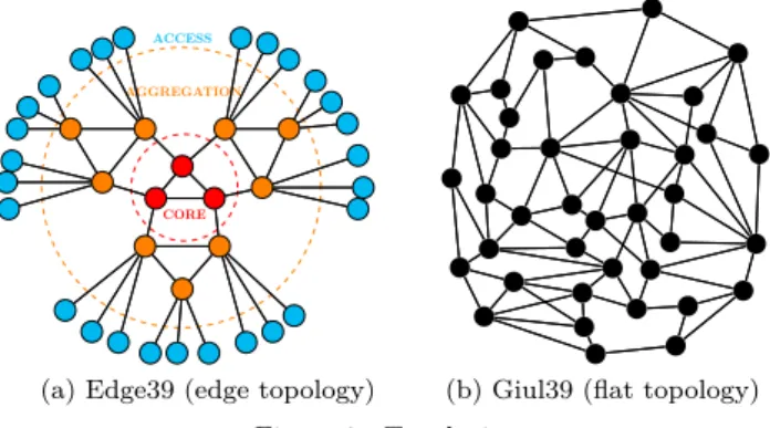
VNFCs placement being constrained by nodes and links capacities, topology and resource distribution in the net-work are likely to play an important role. To evaluate their impact (see Section V), we consider two main types of architectures, as depicted in Figure 1. Flat architectures3, representative of core networks, contain only one level of
15GEx, https://5g-ppp.eu/5gex/
25g-transformer, http://5g-transformer.eu/
3Such architectures can be found at http://sndlib.zib.de
CORE
AGGREGATION
ACCESS
(a) Edge39 (edge topology) (b) Giul39 (flat topology) Figure 1. Topologies
nodes. Edge architectures (described in [6]) are composed of 3 layers: core, aggregation and access and are well suited to study low latency constraints between VNFs.
C. The optimisation model
We address the VNFCPP in a mono-tenant architecture focusing on maximizing the acceptation of new VNFCs. Therefore, we reserve resources in priority on links and nodes where they are abundant, saving them where they are scarce for further requests with potentially stronger requirements. Note that this strategy facilitates the ability of VNFs to scale up/out with the workload, as it spares free resources on many network nodes. This effect is not measured in this paper. The NFVO places requests one by one as they arrive without any prior knowledge of future requests. We formalize this strategy as an Integer Linear Programming (ILP) problem using the notations summarized in Table I.
Table I Notations Name Description
V Set of VNFs to be placed N Set of nodes of the network Succ(v ∈ V ) Outgoing neighboring VNF of v ∈ V Succ(i ∈ N ) Outgoing neighboring nodes of i ∈ N
Bv,w Bandwidth requested to connect
v ∈ V and w ∈ Succ(v)
Bi,j Bandwidth available on the directed link
from i ∈ N to j ∈ Succ(i) Sv Storage requested by v ∈ V
Si Storage available at i ∈ N
Cv Compute requested by v ∈ V Ci Compute available at i ∈ N
Dv,w Maximum delay between v ∈ V and w ∈ Succ(v) Di,j Delay of the directed link from i ∈ N to j ∈ Succ(i)
Tv Processing delay of v ∈ V
∆ Maximum VNFC end-to-end delay P (X) Price of the resource X
1) Variables: Path and VNF embedding are
respec-tively defined by variables x and y. xv,wi,j equals 1 if the traffic sent from v ∈ V to w ∈ Succ(v) uses the directed link from i ∈ N to j ∈ Succ(i), 0 otherwise. yv
i equals 1
2) Objectives: Costs associated to bandwidth (1),
stor-age (2) and CPU (3) allocation: X (v,w)∈V X (i,j)∈N xv,wi,j ∗ Bv,w∗ P (B i,j) (1) X i X v yvi ∗ Sv∗ P (S i) (2) X i X v yvi ∗ Cv∗ P (C i) (3)
We want to give priority to placing VNFs on nodes/links with abundant resources and to preserve nodes/links with scarce resources for future and more demanding requests. To make it costly to install a VNF/path on a node/link with few remaining resources, we associate a price corre-sponding to the inverse of the remaining resources:
P (Bi,j) = 1 Bi,j ; P (Si) = 1 Si ; P (Ci) = 1 Ci (4) To solve the problem, we scalarize our costs with custom coefficients α, β and γ and minimize the result:
min α ∗ (1) + β ∗ (2) + γ ∗ (3) (5)
3) Constraints: The entry and exit nodes of the chain
are represented by two fictive VNFs (entryV N F and
exitV N F ) without any resource needs, so yentryN odeentryV N F = 1 and yexitV N F
exitN ode = 1. The path continuity is enforced by (6)
while (7) ensures that there are no loops along the path between two consecutive VNFs.
X j∈N xv,wj,i −X j∈N xv,wi,j + yvi − yw i = 0, ∀i ∈ N, ∀(v, w) ∈ V (6) X j∈N xv,wj,i + yiv≤ 1, ∀i ∈ N, ∀(v, w) ∈ V (7)
Each VNF must be placed exactly once: X
i∈N
yiv= 1, ∀v ∈ V (8)
Embedding must respect VNF constraints regarding bandwidth capacity and delay :
X (v,w)∈V xv,wi,j ∗ Bv,w≤ B i,j, ∀(i, j) ∈ N (9) X (i,j)∈N xv,wi,j ∗ Di,j≤ Dv,w, ∀(v, w) ∈ V (10)
Node resources must not be exceeded: X v∈V yvi ∗ Cv ≤ C i, ∀i ∈ N (11) X v∈V yiv∗ Sv≤ S i, ∀i ∈ N (12)
VNFC embedding must respect the maximum end-to-end delay acceptable for the full NS:
X (v,w)∈V X (i,j)∈N xv,wi,j ∗ Di,j+ X v∈V X i∈N yvi ∗ Tv ≤ ∆ (13)
IV. VNF placement in a multi-tenant architecture
The problem presented in Section III requires a detailed knowledge of the network topology and resources, which is impossible in a multi-tenant architecture. When the infrastructure and the orchestration service are owned by different actors, VIMs will be reluctant to disclose confidential data and will rather present an abstraction of the network to the NFVO. Therefore, we introduce a two step computation. First, the NFVO performs the placement over abstracted topologies proposed by the VIMs, resulting in a first placement of the VNFs. Then, each concerned VIM must in turn run the algorithm to de-termine the final placement within its infrastructure and update its abstract graph based on resource consumption.
A. The topology abstraction
Over the years, network topology abstraction has mo-tivated a lot of research works [12]. Those works mostly focus on QoS routing over several independent networks. However, since they are not intended to place VNFs, they do not consider the resources of the nodes. In order to be efficient, the abstraction must display a trade off between the accuracy of the information (to allow the NFVO to compute a correct path) and how to hide internal details. The main abstractions for a network topology are the single node, the star and the full mesh [13]. The single node approach is not accurate enough, and the mesh approach fails to represent the node resources. Moreover, computing a full mesh for each possible VNF placement is computationally intractable. Thus we focus on dividing the network in sub-networks, or clusters, each represented by an asymmetric weighed star abstraction. The trade-off is now on the number of sub-networks to consider and their size to get the most representative abstrac-tion while ensuring the non-disclosure of the confidential elements. The division in sub-networks may follow pre-existing administrative divisions or a specific algorithm. We use the algorithm presented in [14] that identifies the clusters based on the link betweenness metric. The size of the clusters is arbitrary and must optimize both computational time and abstraction quality. Each cluster is represented by a star abstract topology including a central node (nucleus) connected via abstracted links (spokes) to the cluster border nodes, themselves connected to neighboring clusters. We choose the nucleus as the node with the highest centrality in the cluster (i.e. the easiest to reach from any point of the cluster, in average), and dimension it with the sum of all non-border nodes resources. We set the parameters of each spoke with
the best possible value, determined by running multiple Dijkstra algorithms between the border node of the spoke and the nucleus focusing on one parameter at a time. Despite its simplicity, this aggressive approach has been proved quite effective in [15]. We add derivations in the star by keeping the links connecting the sub-network’s border nodes to ease the transition from one cluster to the other. By construction, the central nucleus becomes a very attractive node for the objective function, potentially hiding a large number of access nodes with few resources. We mitigate this problem by redefining each price of (4) as the lower price for this resource among the nodes the nucleus represents.
B. The heuristic in a Mono-tenant architecture
The VNFCPP is NP-complete [10], so computing times can become unbearable when the size of the network or the VNFC increases. Most of the works presented in Section II propose heuristics to fasten the resolution, but they are generally based on a specific version of the VNFCPP and do not adapt well to an evolution of the problem param-eters. We propose to extend the abstraction technique used in the multi-tenant scenario to define a heuristic that works with any form of VNFCPP.
When the topology is too large to perform the ILP, the NFVO artificially divides its topology view into several clusters of limited sizes. Note that the abstraction process can be done offline if the topology is not expected to vary quickly over time. The execution of the ILP on abstracted topologies gives a first placement solution that associates each cluster with a set of VNFs to host. The algorithm transforms these results into parameters and executes the ILP a second time on each cluster of the abstract topology. Since the initial ILP is not modified, this heuristic can be applied to any variant of the VNFCPP.
V. Simulations and results
We evaluate the efficiency of our algorithms, using the Gurobi solver and a 12 logical cores Intel Xeon E5-2630.
A. Parameters
1) The topology structure: We selected five flat
back-bone topologies from SDNLib: Atlanta, Brain, Cost, Ger-many50 and Giul39 and designed two custom typical edge topologies: Edge51 (see Figure 1) and Edge39.
2) The resource distribution: We study the impact of
resource distribution with three scenarios. In the Low concentration (L) scenario, the nodes and links of all topologies have exactly the same resources: the nodes have 80 CPU units and 100 storage units and the links have 1000 bandwidth units. This is unlikely to happen in real life where central datacenters have much more capacity than edge ones. The other scenarios focus on the topologies with comparable number of nodes and links: Edge39, Edge51, Giul39 and Germany50. The total amount of resources in the network is the same as in the
first scenario but the node resource distribution changes. Nodes are categorized in access, aggregation and core nodes (which is straightforward for Edge39 and Edge51). We classify Giul39 nodes (resp. Germany50) by selecting the same amount of node in each category as with Edge39 (resp. Edge51), according to their centrality. The highest centrality corresponds to core nodes since high-capacity nodes are likely to be placed at strategic location in the network. In the Medium concentration (M) scenario, each node category has 33% of the network total amount of resources whereas in the High concentration (H) scenario core, aggregation and access nodes detain respectively 60%, 30% and 10% of the total amount of resources.
3) VNF delay tolerance: We study the influence of
the latency constraint of the end-to-end NS and between the VNFs on the overall chain placement by fixing each link delay to 100 units and considering a large range of delay bounds. We determine the bounds by introduc-ing a variable called delay factor. A delay bound takes into account the topology diameter in order to obtain comparable results between topologies. The delay factor takes the values 50, 100, 150, 200, 300, 400 and 800. For each network service, we randomly select the end-to-end latency constraint ∆ and Dv,w the latencies between
VNFs using (14) and (15).
delayF actor ∗ networkDiameter
4 ≤ ∆ ≤
numberOf V nf s ∗ (delayF actor ∗ networkDiameter ∗ 2
+ maxP rocessingDelay) (14)
0 ≤ Dv,w≤ delayF actor ∗ networkDiameter
2 (15)
A delay factor of 50 corresponds to an average delay between VNFs of one hop, while for a delay factor of 400, it is equivalent to the diameter of the network.
4) NS lifespans: NS lifespans represent the time a
NS will be present in the network. For convenience, the measure of the time in our experiment is based on the reception of requests. For example, the first NS may indicate a lifespan of 200 requests. When the 200th request is received, the NS expires and the reserved resources are released. As for delay tolerance, lifespan values depend on the topology. Indeed, in our model, the resources of the topology are directly proportional to its size. For the same lifespan a small topology such as Atlanta could be satu-rated while a large one like Brain would have barely dent its resources. For each topology we define the inflexion point as the number of requests from which the acceptance rate of both our ILP and the baseline algorithm (see V-B) become very low, marking the beginning of the saturation of the network.We analyze eleven lifespan values for each topology (from 10% to 100% of the inflexion point, plus the infinite lifespan). An approximation of the value of the inflexion point is sufficient since its purpose is just to allow a good distribution of the lifespan measurements.
German yL CostL A tlan t aL
Giul39L Edge39L Edge51L BrainL
Edge39M
German
yM
Giul39M Edge51M Edge39H Giul39H
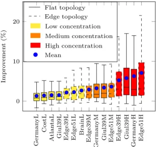
German yH Edge51H 0 10 20 Impro v emen t (%) Flat topology Edge topology Low concentration Medium concentration High concentration Mean
Figure 2. Performance of the ILP compared to a bandwidth-only optimization strategy
5) Other parameters: The value of the following
pa-rameters are chosen randomly in consistency with [5], [6], [8], [9] and [11]. Chains comprise between 2 and 5 VNFs. Any VNF consumes between 0 and 10 CPU and storage units, and the link between two consecutive VNFs requests between 1 and 10 bandwidth units. We choose arbitrarily a delay of treatment for each VNF between 0 and 100. Entry and Exit points of the chain are randomly chosen in the network, and may eventually be the same. In order to improve the readability of the results, we filter the NS requests submitted to the network to ensure that they are feasible when the network is empty.
B. Global optimization evaluation
We evaluate the performance of our ILP by comparing it with a baseline solution that only considers the bandwidth optimisation (α = 1, β = 0 and γ = 0 in (5)). We chose the coefficients of our ILP α = 1, β = 4 and γ = 7 to compensate for the disparity in resources. Measures in this section were obtained as follows : for a given algorithm and set of parameters (topology, lifespan, delay factor) the performance is the averaged number of embedded NSs computed over 2.000 requests after the inflexion point.
Figure 2 provides an overview per topology of the improvement obtained with the ILP compared to the base-line in terms of number of embedded NS. Each boxplot is composed of 77 results obtained with the 7 values of the delay parameter and the 11 values of the lifespan parameter. We observe that the higher the concentration the better the improvement, especially when the concen-tration is High. In practice, the High distribution seems more likely to happen as access nodes may be composed of one cabinet, or even one computer, whereas central datacenter resources are often considered as infinite. This confirms our hypothesis: it is crucial to spare nodes with
10 20 30 40 50 60 70 80 90 100 ∞ 50 100 150 200 300 400 800 0 20
lifespan(%) delay factor
impro
v
emen
t
(%)
Figure 3. Performance of the ILP vs. baseline in Edge51 topology under high resource concentration
few resources so as not to reject future NSs with strong latency requirements due to a lack of nodes with resources close enough to meet them. The lack of impact of the topology type (flat or edge) can be explained by their small size: the path length from an access node to a central node is quite similar. Lastly, we can see that even for High concentration the median improvement remains under 5%, while the mean improvement lies between 5% and 10%. Top performance can reach 15% to 23%. In order to explain those disparities we will take a closer look to the best performing topology (Edge51) in Figure 3.
Figure 3 has the same general aspect for each topology and for other resource concentrations (although scales differ), but for size limitation reasons we cannot show them all. The best improvement is for delay factors of 50, 100, 150. Higher delay factors leads to very weak latency constraints and the VNFCs can involve long detours to take resources in the core nodes when other options are exhausted, reducing the benefit of sparing resources in the access. On the contrary, requests with strong latency con-straints benefit from good resource management because they could no longer be accepted in the event of resource depletion in an area. The improvement is maximized for lifespans between 30% and 40% of the number of requests at the inflexion point. With lower lifespans the network is underused, and a wise placement is useless. Higher lifespans saturate the network and only the requests that require small resources are accepted.
C. Heuristic evaluation
We evaluated our heuristic considering a wide range of sizes for edge topologies (based on the Edge39 scheme). We generated topologies, referred to as edgeN, composed of N core nodes, N clusters of aggregation nodes inter-connected by the core with 2 ∗ N + 1 aggregation nodes divided into two layers in each cluster, and 4 ∗ N access nodes connected to each aggregation node.
We first analyze the performance of the heuristic against the holistic ILP. The network is divided into clusters composed of a maximum of 100 elements and each request tries to place 10 VNFs. Each node has 80 CPU units and 60 storage units, and each link has 800 bandwidth units.
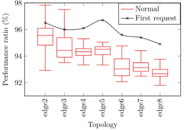
edge2 edge3 edge4 edge5 edge6 edge7 edge8 92 94 96 98 Topology P erformance ratio (%) Normal First request
Figure 4. Heuristic cumulative acceptation ratio vs. holistic solution
0 1 2 3 4 10−1 100 101 # of nodes (·103) R un time (s) ILP Heuristic (a) 10 VNFs Cluster max size=100
0 5 10 15 20 101 102 # of nodes (·103) R un time (s) ILP Heuristic (b) 20 VNFs Cluster max size=3000 Figure 5. Heuristic vs holistic solution runtime
The delay factor is 100. We compare the cumulative accep-tation ratio of the heuristic during two phases: when the network is empty (first request) and before the inflexion point (“normal”). The Figure 4 shows the efficiency of the heuristic since we achieve a performance ratio between 93% and 96% between the first request and the inflexion point. When the network is empty the first request is accepted 96% of the time due to our aggressive abstraction method that may propose paths that are more appealing than feasible paths but that do not fit in the physical infrastructure. We analyzed the computational time of our heuristic versus the holistic ILP. We take into account the time required by the heuristic to reserve and release the resources, as it implies additional computations. Although the heuristic can be multi-threaded, we use only one thread in all our experiments. The Figure 5a shows that although runtimes are comparable on small instances, heuristic runtime remains stable while network size grows. We increased the sizes of the networks, we doubled the number of VNFs to be placed and allowed the heuristic to form clusters of up to 3000 nodes. The results, presented in Figure 5b, are very similar to the previous ones pointing out that our heuristic can handle large-scale problems without facing increased computation times.
VI. Conclusion and perspectives
In this paper, we propose an algorithm that solves the Virtual Network Function Chain Placement Problem allowing a fine management of the resources in order to
satisfy the greatest number of requests. We show how network resource concentration and request constraints influence the Virtual Network Function Chain placement, unlike the topology structure. For multi-tenant archi-tectures, we propose a method allowing the Virtualized Infrastructure Manager to expose an abstract view of the infrastructure topology. Leveraging on this approach we propose an heuristic to solves the Virtual Network Function Chain Placement Problem in multi-tenant ar-chitectures and deal with the computational complexity of the placement, both for mono- and multi-tenant architec-tures. For future work, we plan to design the abstraction recursively and quantify the impact of the size of the clusters, then to investigate the offline re-optimisation of the placement and Virtual Network Function sharing.
References
[1] “Network Functions Virtualisation, An Introduction, Benefits, Enablers, Challenges & Call for Action.” ETSI, Oct. 2012. [2] ETSI GS NFV-MAN 001, “Network Functions Virtualisation
(NFV); Management and Orchestration,” 12 2014, version 1.1.1.
[3] M. Patel, D. Sabella, N. Sprecher, V. Young, and Y. C. Hu, “Mobile edge computinga key technology towards 5g,” ETSI white paper, vol. 11, no. 11, 2015.
[4] J. Gil Herrera and J. F. Botero, “Resource Allocation in NFV: A Comprehensive Survey,” IEEE Transactions on Network and Service Management, vol. 13, no. 3, pp. 518–532, Sep. 2016. [5] O. Soualah, M. Mechtri, C. Ghribi, and D. Zeghlache, “Energy
Efficient Algorithm for VNF Placement and Chaining,” in 2017 17th IEEE/ACM International Symposium on Cluster, Cloud and Grid Computing (CCGRID). Madrid, Spain: IEEE, May 2017, pp. 579–588.
[6] B. Addis, D. Belabed, M. Bouet, and S. Secci, “Virtual network functions placement and routing optimization,” in Cloud Networking (CloudNet), 2015 IEEE 4th International Conference on. IEEE, 2015, pp. 171–177.
[7] Q. Sun, P. Lu, W. Lu, and Z. Zhu, “Forecast-assisted NFV service chain deployment based on affiliation-aware vNF place-ment,” in Global Communications Conference (GLOBECOM), 2016 IEEE. IEEE, 2016.
[8] A. Dwaraki and T. Wolf, “Adaptive Service-Chain Routing for Virtual Network Functions in Software-Defined Networks.” ACM Press, 2016, pp. 32–37.
[9] F. Carpio, S. Dhahri, and A. Jukan, “VNF placement with replication for Loac balancing in NFV networks,” in Communications (ICC), 2017 IEEE International Conference on. IEEE, 2017.
[10] Z. Chen, S. Zhang, C. Wang, Z. Qian, M. Xiao, J. Wu, and I. Jawhar, “A Novel Algorithm for NFV Chain Placement in Edge Computing Environments,” in 2018 IEEE Global Communications Conference (GLOBECOM). IEEE, Dec. 2018.
[11] C. Pham, N. H. Tran, S. Ren, W. Saad, and C. S. Hong, “Traffic-aware and Energy-efficient vNF Placement for Ser-vice Chaining: Joint Sampling and Matching Approach,” IEEE Transactions on Services Computing, 2017.
[12] S. Uludag, K.-S. Lui, K. Nahrstedt, and G. Brewster, “Analysis of topology aggregation techniques for QoS routing,” ACM Computing Surveys (CSUR), vol. 39, no. 3, p. 7, 2007. [13] W. C. Lee, “Topology aggregation for hierarchical routing in
ATM networks,” ACM SIGCOMM Computer Communication Review, vol. 25, no. 2, pp. 82–92, Apr. 1995.
[14] L. C. Freeman, “A set of measures of centrality based on betweenness,” Sociometry, vol. 40, no. 1, pp. 35–41, Mar. 1977. [15] T. Korkmaz and M. Krunz, “Source-oriented topology aggre-gation with multiple QoS parameters in hierarchical networks,” ACM Transactions on Modeling and Computer Simulation, vol. 10, no. 4, pp. 295–325, Oct. 2000.