To cite this document:
Farre-Ponsa, Roser and Strenge, Joachim H. and Gutierrez,
Andrea and Grave, Julien and Lucas, William and Rouanne-Labe, Anne and Peille,
Philippe and Pierl, Christoph and Lizy-Destrez, Stéphanie and Mignot, Jean JUMPSAT:
Qualifying three equipments in the CubeSat mission. (2013) In: 64th IAC - International
Astronautical Congress, 23 September 2013 - 27 September 2013 (Beijing, China).
O
pen
A
rchive
T
oulouse
A
rchive
O
uverte (
OATAO
)
OATAO is an open access repository that collects the work of Toulouse researchers and
makes it freely available over the web where possible.
This is an author-deposited version published in:
http://oatao.univ-toulouse.fr/
Eprints ID: 9693
Any correspondence concerning this service should be sent to the repository
administrator:
[email protected]
JUMPSAT: QUALIFYING THREE EQUIPMENTS IN ONE CUBESAT MISSION Mrs. Roser Farre-Ponsa and Mr. Joachim H. Strenge
ISAE - Institut Supérieur de l’Aéronautique et de l’Espace, France, [email protected], [email protected]
Mrs. Andrea Gutierrez*, Mr. Julien Grave†, Mrs. Anne Rouanne-Labe‡, Mr. William Lucas§, Mr. Philippe Peille**, Mr. Christoph Pierl††, Mrs. Stéphanie Lizy-Destrez‡‡, Mr. Jean Mignot§§
JUMPSAT is a 3-Unit CubeSat mission expected for launch in 2017. It is a collaborative project involving the French research institutes CNES and ONERA as well as two universities, the Institut Supérieur de l'Aéronautique et
de l'Espace and TELECOM Bretagne.
The main mission objectives are the technological verification of both the three-axis attitude control system as well as the verification of two embedded payloads: A low cost Star Tracker developed by ISAE-Supaero for future small satellite missions and a directional radiation sensor for precise mapping of the Earth radiation belt.
This article focuses on the mission concept and the status of the mission design in fall 2013. Main mission parameters are introduced, with emphases on the characteristic properties of the Jumpsat mission, as for example the choice of a sun-synchronous elliptical low-Earth Orbit, which is necessary to be in compliance with the payload requirements and at the same time to ensure space debris prevention. Furthermore, due to the limited observation time of a polar satellite, it was decided to utilize a distributed ground station network on S-band frequency for ensuring the necessary communication bandwidth for up- and downlink. The space segment will be equipped with deployable solar panels for improving the thermal and power budget of the overall system. Finally, a brief overview of the specifications and design of the attitude control system and both payloads are also given in the article.
I. MISSION OVERVIEW
Jumpsat is a three-unit CubeSat mission proposed by the Institut Supérieur de l'Aéronautique et de l'Espace (ISAE) in 2012. The main missions of the satellite are both technological as well as scientific:
i. Technological verification / space qualification of a Star Tracker, which is currently under development by ISAE-Supaero for future use in small satellite systems.
ii. Mapping of the properties of the Earth radiation belt with emphasis on the South
Atlantic Anomaly using a directional radiation
sensor under development by ONERA. iii. Technological verification / space qualification
of the three-axes attitude control system of the Jumpsat space segment.
Naturally, besides the technological and scientifical goals of the mission, another important benefit is the high academic value for both students and the involved universities. While being managed by the university, many responsibilities are given to students, hence improving technical knowledge, soft skills and finally the professional network.
The satellite will be built according to the 3U CubeSat standard as given by Calpoly University [1] and it is a cooperative mission of ISAE-Supaero together with TELECOM Bretagne, the Massachusetts Institute
of Technology and the French research institutes
ONERA and CNES.
Fig. 1: CAD model of the preliminary internal Jumpsat design
II. MISSION ANALYIS II.I Orbit Selection
The following are the four main requirements influencing the orbit selection of the space segment:
i. The radiation sensor is designed to measure the distribution of the radiation belt of the Earth. Scientific valuable results require a minimum altitude at an Apogee of 700km.
ii. Furthermore, to be able to accomplish global mapping of the radiation belt, a high inclination is mandatory.
iii. The current regulations concerning the prevention of space debris require a passive re-entry of the space segment within 25 years after launch for satellites without propulsion system.
iv. Finally, to simplify operations and to increase mission operations efficiency, the sun/eclipse ratio of the orbit was optimized.
According to those requirements one orbit was chosen for further mission analysis: An elliptical 1000-500 km sun-synchronous dawn-dusk orbit. The main reasons are listed below:
§ The apogee altitude of 1000 km is sufficient for scientific use of the radiation sensor.
§ The perigee is located in denser layers of the atmosphere, thus reducing the lifetime of the system. Preliminary simulations predict an orbit lifetime of 15.5yrs.
§ The inclination of 98.38° allows mapping of both hemispheres almost completely.
§ A dawn-dusk orbit ensures solar power during the majority of the mission duration, thereby increasing mission operation efficiency. The following table provides exemplary orbital data for a launch in September 2017. Semi-major axis [km] Eccentricity Inclination [°] Right Ascension of Ascending Node [°] Argument of Perigee [°] 7128 0.0357 98.38 10 30
Table 1: Proposed orbit of the Jumpsat II.I Ground Station Network
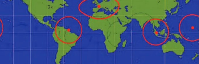
A visibility and data budget study was performed using the software package SATORB developed by ISAE. Using rough assumptions concerning the housekeeping and payload data production, the following conclusions were drawn:
i. Due to the high inclination of the space segment, the visibility duration of a single ground station e.g. in Toulouse would not be sufficient for efficient operations.
Fig. 2: Locations of the distributed ground station network [2]
ii. To ensure the possibility to downlink major amounts of data, e.g. for calibrating the attitude control system, it is advantageous to utilize a communication system with a higher bandwidth, such as UHF or S-band.
Cooperation with the Massachusetts Institute of
Technology could provide access to a highly compact,
low power, half-duplex S-band radio, including the use of a distributed ground station network. For this reason, the Jumpsat will operate using S-band Telemetry and Telecommand. The location of the ground station network is given in Figure 2.
III. SPACE SEGMENT III.I Payload Systems
Both main payloads are still under development, however, preliminary properties are listed below.
Star Tracker
The Star Tracker implemented on the Jumpsat space segment is a commercially available camera system, which utilizes the software, which is designed for the final Star Tracker developed by Supaero, as given in Figure 3.
Radiation Sensor
The radiation sensor is currently under development by ONERA and features not only the detection of impacting particles, but also provides certain properties concerning their direction. The design is highly integrated to ensure the compatibility with the limited resources on-board a CubeSat [3].
III.II Bus systems
Most spacecraft bus subsystems will be manufactured using commercially available systems or provided by direct cooperation with other entities: The thermal and structural subsystem, the On-Board-Computer (OBC), the Electrical Power Subsystem (EPS) and the communication subsystem (COM). It features among others:
§ A passive thermal control subsystem designed by ISAE.
§ An EPS with sufficient battery capacity for the Launch & Early Orbit Phase (LEOP) and eclipse phases during the mission.
§ Deployable solar panels for increased solar power production and for thermal reasons.
§ A S-band half-duplex radio including a directional panel antenna.
The design of the EPS was performed using a common analytical approach as well as numerical methods, to take into account the variability of the eclipse duration during different seasons in the year as well as the LEOP.
The design of the attitude control system is performed by ISAE supported by CNES and is given in detail in chapter III.
III.III Internal architecture
The design of the internal architecture, namely the arrangement of the different internal subsystems within the 3U structure was one of the major design challenges of the Jumpsat mission in the current mission status. Using a well structured systems engineering approach, different scenarios were evaluated and optimized according to the following criteria:
§ Pursuing a geometrically central centre of gravity. § Avoidance of issues due to electromagnetic
interference.
§ Positioning of the Star Tracker, the Radiation sensor and the communications antenna according to their requirements.
§ Reduction of the necessary wiring length and mass.
§ Improving the internal thermal design by avoiding
hot spots.
§ Reduction overall system complexity.
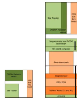
The result is a highly integrated design of all subsystems, in which most systems are connected using one shared data/power bus. Figure 4 gives an overview of the resulting design in both top and lateral view. However, in the current mission phase, it is not yet possible to finally confirm the feasibility of this design. Among other reasons, currently no sufficient simulation models are available to determine the risks of electromagnetic interference related issues or internal thermal problems.
Fig. 4: Preliminary internal design of the Jumpsat space segment. The left drawing is the upper view, while the drawing on the right visualizes the current design from a lateral point of view. III.IV External architecture
As given in chapter I, the Jumpsat space segment is designed to be a 3U CubeSat, according to the mass and volume requirements defined by the Calpoly University [1]. However, while this imposes strong restrictions concerning the dimensions during the launch, the system can change dimensions after separation from the launch vehicle. In case of the Jumpsat, this possibility was investigated by analysing the deployment of solar panels. Three different possible final configurations were compared, as given in Figure 6. The following criteria were essential for the choice of the final design:
§ A deployed configuration increases the solar power production significantly.
§ The properties of the surfaces, which are exposed after deployment of the solar panel, can be chosen according to thermal design requirements. This allows e.g. to radiate more heat into space, which is according to a preliminary thermal analysis crucial to ensure acceptable internal temperatures during the mission.
§ The third configuration of Figure 6 requires an attitude, in which the upper face of the satellite is exposed to the sun. This is not in compliance with the requirements of the star tracker payload, whose optics are mounted on this surface.
Accordingly, the configuration shown in the middle of Figure 5, the lateral deployable configuration was chosen as preliminary external design.
Fig. 5: Three different compared external architectures. The classical configuration is shown on the left, the lateral deployable configuration in the middle and the flower configuration on the right. III.V Kinematic analysis
After defining the preliminary internal and external architecture, the design was modelled using CAD to verify the geometric and kinematic assumptions of the preliminary model. It is shown exemplary in Figure 1.
IV. ATTITUDE CONTROL SYSTEM IV.I Hardware components
The Jumpsat space segment will be equipped with a continuous three-axes attitude control system with low response durations and high accuracy. For this reasons, it will be equipped with a highly integrated set of three reaction wheels and a sun sensor in addition to an actuator/sensor package, which is based on the Earth’ magnetic field. The following components will be integrated into the final satellite:
§ Magnetometer: SSVB Stand Alone Magnetometer § Magnetorquer: ISIS iMTQ
§ Reaction wheels: Maryland Aerospace MAI-101 § Two-axes sun sensor: SSOC-A60
The attitude control software is under development by students of ISAE and will be integrated into the On-Board-Computer of Jumpsat.
IV.II Attitude Controller
All attitude control sensors and actuators are being utilized by the On-Board Computer of the Jumpsat, which will run a feedback controller developed in C by ISAE. It is based on the B-dot control law, a Quaternion Feedback Controller and the control law for Magnetic Unloading of Momentum Exchange Devices.
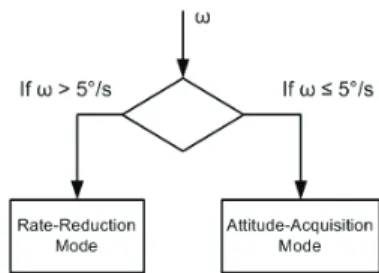
In the current stage of development, several different operation modes have been identified. The following two major modes have been studied in detail:
1. Rotational Rate Reduction Mode: An operational mode to eliminate the rotational energy of the system after separation from the launch vehicle or after idle times of the system. It is based on the B-dot control law and utilizes the Magnetometer and Magnetorquer only. 2. Attitude Acquisition Mode: The main operation
mode of the ACS system, based on all available sensors and actuators and using the Quaternion Feedback Control law and the control law for unloading of the reaction
wheels. It allows pointing of the satellite in any direction in any of the reference frames.
Fig. 6: Principle of mode selection
The choice of operation mode will be commanded by telecommand from the ground station or by automatic on-board command (See: Figure 6).
IV.III Verification
In parallel to the development of the controller, a suitable test environment is being developed using Matlab/Simulink®. Currently, it features:
§ Simulation of the kinematic properties of the satellite using the results of the CAD analysis § Orbit propagator for two-body problem
§ Estimation of disturbance momentums due to aerodynamic drag, solar radiation, the residual magnetic dipole and gravity gradient
§ Ideal representations of sensors and actuators The next task is the development of realistic sensor and actuator models. However, using the current model, initial conclusions can be drawn:
§ Reduction of rotational velocities by the B-Dot controller in order to change the operational mode. § Successful operational mode transition between
two modes using different control laws.
§ Ability to perform large angle maneuvers due to a modified quaternion feedback controller
V. CONCLUSION
Although the Jumpsat mission is in an early stage of development, the first important accomplishments were archived:
§ Basic mission concept was developed.
§ Preliminary structural, power, data and thermal feasibility studies were performed and confirm the mission concept.
§ Valuable cooperation could be established. § Due to the use of an uncommon orbit, the Jumpsat
mission depends probably on an individual launch. Currently, the school is negotiating a possible launch opportunity.
§ Based on the preliminary internal architecture, it was decided to purchase major subsystems already to allow early system and software verification and to improve the hands-on experience of the involved students.
§ First successes in developing the attitude controller indicate the feasibility of a development of the entire attitude control system software by the university.
However, the majority of workload is still ahead, the following listing indicates the major goals for the following year:
§ Detailed models are necessary for numerous design domains, as for example:
o Internal and external thermal design o Electromagnetic inferences
o Structural design o Power budget o Link budget
o Orbit lifetime analysis
§ As soon as the bus components, which were already ordered, are being delivered, all systems have to be verified to ensure inter-compatibility, compatibility with the on-board software and space environment resistibly.
§ Following the mission concept as given in Chapter II, a preliminary mission operations plan will be developed to state the requirement of the power and data budget more precisely.
§ Finally, the attitude control software has to be equipped with realistic sensor and actuator models for providing a suitable test-platform for future development of the attitude controller. Furthermore, an in-house test bench is under development by ISAE.
*
ISAE, France, [email protected] †
ISAE, France, [email protected] ‡
ISAE, France, [email protected] §
ISAE, France, [email protected] **
ISAE, France, [email protected] ††
ISAE, France, [email protected] ‡‡
ISAE, France, [email protected] §§
CNES, France, [email protected]
[1] Calpoly University (2009), Revision 12, CubeSat Design Specification, http://cubesat.calpoly.edu/ [2] Grave, J. et al. (2012), JumpSat: Qualifying three equipments in one CubeSat mission,
Toulouse, ISAE – Supaer o