UNIVERSITÉ DU QUÉBEC
À
MONTRÉAL
FULL-DUPLEX RELAYING WITH SELF-INTERFERENCE
AVOIDANCE
THESIS
SUBMITTED
IN PARTIAL FULFILLMENT OF THE REQUIREMENTS FOR
THE DEGREE OF
MASTER IN ELECTRICAL ENGINEERING
BY
MOHANED CHRAITI
UNIVERSITÉ DU QUÉBEC À MONTRÉAL Service des bibliothèques
Avertissement
La diffusion de ce mémoire se fait dans le respect des droits de son auteur, qui a signé le formulaire Autorisation de reproduire et de diffuser un travail de recherche de cycles supérieurs (SDU-522- Rév.01-2006). Cette autorisation stipule que «conformément à l'article 11 du Règlement no 8 des études de cycles supérieurs, [l'auteur] concède à l'Université du Québec à Montréal une licence non exclusive d'utilisation et de publication de la totalité ou d'une partie importante de [son] travail de recherche pour des fins pédagogiques et non commerciales. Plus précisément, [l'auteur] autorise l'Université du Québec à Montréal à reproduire, diffuser, prêter, distribuer ou vendre des copies de [son] travail de recherche à des fins non commerciales sur quelque support que ce soit, y compris l'Internet. Cette licence et cette autorisation n'entraînent pas une renonciation de [la] part [de l'auteur] à [ses] droits moraux ni à [ses] droits de propriété intellectuelle. Sauf entente contraire, [l'auteur] conserve la liberté de diffuser et de commercialiser ou non ce travail dont [il] possède un exemplaire.»
UNIVERSITÉ DU QUÉBEC
À
MONTRÉAL
RELAYAGE FULL-DUPLEX AVEC PRÉVENTION DE
L'AUTO-INTERFERENCE
MÉMOIRE
PRÉSENTÉ
COMME EXIGENCE PARTIELLE
DE LA MAÎTRISE EN GÉNIE ÉLECTRIQUE
PAR
MOHANED CHRAITI
ACKNOWLEDGEMENTS
The master journey is a funny one. At the beginning, you have no idca whcre you arc going, but you know that you have to get thcre. 'At the end, when all is said and done, you still have no idea whcre you arc going. But you have become very good at getting there. lt is not possible to complctcly express my gratitude to my advisors, Profcssor Wessam Ajib and. Jean-François Frigon, for all the ycars of guidance and tolerance they have given me. 1 recognize that 1 am not the casiest student to work with. They fostered an cnvironment where 1 could explore frcely, find out what 1 liked, make attempts at what 1 fancied, and finally succeed in what 1 did. As a graduate student, 1 could not have asked for more. As a persan, 1 am forevcr indebted.
1 am gratcful for the time 1 have spent in the Télécommunication, Réseaux, Infor-matique Mobile et Embarquée Laboratory, cspccially for the collcagues who have made the whole experience memorable. Many of my insights have come out of our hours of discussing cvcrything from rcsearch to life's little annoyanccs. Elmahdi, Zakaria, Taher, Monccf, Zoubeir, Omar, Olfa and many othcrs have made my stay unforgettable. 1 am also grateful to my family, bath for my very existence and for supporting me throughout my studies.
In memory of my father
To my mother, brother
and
sister
LIST OF FIGURES ABBREVIATIONS . RÉSUMÉ .. ABSTRACT INTRODUCTION 0.1 Background . 0.2 Research Problem .
CONTENTS
0.3 Key Innovations in this Thesis . 0.4 Outline of this Thesis .
CHAPTER 1
LITERATURE REVIEW .
1.1 MIM 0 and Information Theory 1.1.1 Capacity of wireless channel
1.1.2 Mutiple-lnput Multiple-Output wireless system 1.2 Full-Duplex Radio . . . .
1. 2.1 Main challenge in full-du pl ex transmission 1.2.2 Self-interference mitigation . Xlll xv xvii X lX 1 1 4 5 6 9 9 9 12 18 18 19 1.3 Relay Channel . . . . 20 1.4 Full-Duplex Rclaying . 22 1.5 Notations . . . 24 CHAPTER II
ON THE PERFORMANCE OF FULL-DUPLEX RELAY CHANNEL UN-DER THE CONSTRAINT OF NULL SELF-INTERFERENCE POWER . 25
x 2.1 System Madel . . . . 2.1.1 Signal madel 2.1.2 Self-interference pre-nulling 26 26 27 2.2 Performance Analysis Under Null Received Self-Interference Power Constraint 27
2.2.1 Capacity analysis . . . . 2.2.2 Maximum Mutual Information Analysis
2.3 Performance of FD Decode-and-Forward Relay Channel with Rayleigh
28
35
Fading Channels 37
2.4 Conclusion . . . 38 CHAPTER III
DISTRIBUTED ALAMOUTI FULL-DUPLEX RELAYING SCHEME WITH
DIRECT LINK . . . 39
3.1 System Madel . . . 40
3.2 Full-Duplex Relaying with Alamouti Encoding (FDAE) 41
3.3 Modified Full-Duplex Rclaying with Alamouti Encoding (MFDAE) 45
3.4 N umerical Results 49
3.5 Conclusion . . . 50
CHAPTER IV
OPTIMAL LONG-TERM POWER ADAPTATION FOR FD DECODE-AND-FORWARD RELAY CHANNEL . . . 53 4.1 Capacity of Fading Channel with Channel Side Information 53
4.2 Problem Formulation . . . . 54
4.3 Optimal Power Distribution 56
4.3.1 Optimal power distribution for Rayleigh fading channels 58 4.3.2 Optimal power distribution for discrete distribution channels . 58 4.4 Numerical Results 4.5 Conclusion . CONCLUSION APPENDIX A 59 62 65
BIBLIOGRAPHY . . . .
xi
69
LIST OF FIGURES
Figure
1.1 Point-ta-point MIMO system 1.2 Multi-uscr MIMO system . 1.3 Rclay channel . . . .
2.1 Full duplex transmission process . 2.2 Full duplex relay system . . .
3.1 MFDAE transmission process during two TSs
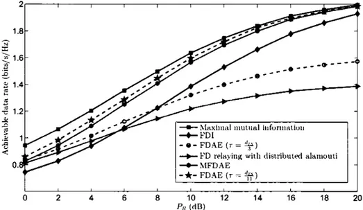
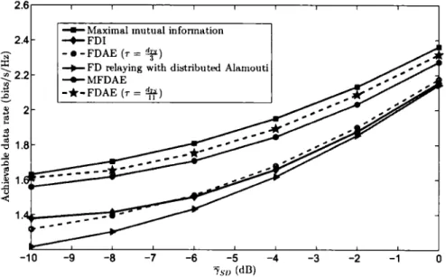
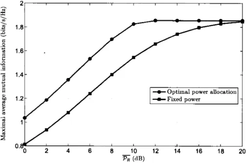
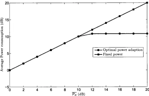
Page 14 17 21 26 31 46 3.2 End-ta-end achievable data rate versus Pn (Ps = 20dB) . 50 3.3 End-ta-end achievablc data rate versus "isD (Ps = Pn = lOdB) 51 4.1 Mutual information versus Pn 61 4.2 The relay power consumption versus Pn 62 4.3 Mutual information versus "isD 63 4.4 The rclay power consumption versus 'YsD 63
ABBREVIATIONS
AWGN Additive white Gaussian noise AF Am plify-and-forward
c
CapacityCSI Channel side information D Destination
DF Decode-and-forward FD Full-duplex
FDAE Full-duplex with Alamouti encoding FDI Full-duplex with interference
1 Mutual information
MFDAE Modified full-duplex with Alamouti encoding MIMO R
s
SIR SNR Multiple-input multiple-output Re lay SourceSignal ta interference ratio Signal ta noise ratio
RÉSUMÉ
Transmettre et recevoir des signaux simultanément( communication full-duplex) sur la même bande de fréquence n'est possible que grâce à la prévention de l'auto-interférence avant d'atteindre le convertisseur analogique numérique de l'antenne de reception. Une contrainte sur la prévention de l'auto-interférence reçue doit être imposée sur le noeud full- duplex ct cette contrainte doit être considérée dans l'analyse de la capacité d'un canal de rclayage full - duplex. Cc travail étudie le problème d'évaluation de performance d'un système de rclayagc full- duplex sous la contrainte d'une auto-interférence nulle. Tout d'abord, nous calculons la capacité de canal de rclayagc full -duplex. En se basant sur ce résultat, nous obtenons une formule explicite de l'information mutuelle maximale d'un canal de rclayage full- duplex "décoder-ct-transférer" où l'état des canaux est disponible au niveau du relai.
En outre, nous proposons deux algorithmes de rclayage, basés sur l'encodage dis-tribué Alamouti, qui à la fois résolvent efficacement le problème de l'interférence due au lien direct ct préviennent complétcmcnt l'auto-interférence. Nous montrons que les performances de ces deux algorithmes s'approchent de l'information mu-tuelle maximale. Ensuite, en supposant que le rclai connaît parfaitement l'état des canaux ainsi que leurs statistiques, nous calculons la distribution de puissance op-timale dans le temps qui permet d'atteindre l'information mutuelle maximale. Les résultats numériques prouvent que la connaissance de l'état des canaux ct leurs statistiques fournit un gain d'information mutuelle important ct réduit l'énergie consommée.
ABSTRACT
Full-duplex transmission is fcasible only through self-interference avoidancc, be-fore rcaching the analogue to digital convcrtor at the front-end of the receivcd antcnna. In arder to grant fcasibility, a constraint on the rcccivcd self-interference power have to be imposcd on the full-duplex node and this constraint should be considcrcd in analyzing the full-duplex relay channel capacity. This thcsis rc-considcrs the problcm of cvaluating the performance of full-duplex rclay channel, with channel sidc information at the rclay, undcr the constraint of null rcccivcd self-interference power. First, the corrcsponding capacity question is formulatcd and answercd. Bascd on this rcsult, wc derive an cxplicit formula for the maxi-mum mutual information of full-duplex dccode-and-forward rclay channel whcn the rclay has instantancous channel statc knowlcdgc. Morcovcr, wc propose two rclay transmission schcmcs, based on distributcd Alamouti encoding, which takc into account the self-interference avoidancc and cfficicntly mitigate the impact of the direct link interference to achicve ncar maximum mutual information perfor-mance. Ncxt, assuming that the rclay pcrfcctly knows the channel statc and the channel statistic, wc derive the optimal power distribution in timc that achicvcs the maximum mutual information. Numcrical rcsults show that this full statc in-formation providcs significant mutual inin-formation gain and rclay power saving comparcd to the case of limitcd instantancous channel statc knowlcdgc.
INTRODUCTION
0.1
Background
Communication has always bccn a fundamcntal nccessity through the course of human history. Because wc are living in a society, contributing to society, sharing with the society, communication is a natural part of who wc arc. The efforts to makc communication a better experience have always bccn with us. The limita-tions of communication have bccn continuously rcduccd by the tcchnology. For instance, one innovation that makes the communication a better experience was wireless communication systems. lt extended the maximum distance to commu-nicate and amcliorated the life of mankind.
Different requiremcnts of communication systems have come into play as we pro-gressed. The extent of security, speed, accuracy and distance has put the challenge into different fields, compclling us to invcnt different forms of communication. Y et, thcre has always bccn one goal which is common for ali forms of communication systems : achicving high data rate. Wc arc living in a world in which wirclcss traf-fic grows incrcasingly and wirclcss applications are gctting more and more grccdy for data rate and accuracy. The challenge to design the ncxt-gcncration of wire-lcss systems, with high throughput and bcttcr covcragc, bccomcs more and more difficult.
An important mctric, known as channel capacity, is widcly uscd to charactcrizc wirclcss communication systems by giving the thcatrical maximum rcliablc trans-mission rate. It is dcfincd in information thcory as the maximum rate of rcliable
2
communication that can be supportcd by a communication system. Sincc the chan-nel capacity of a wirclcss communication system may point out if the system can handlc more wirelcss traffic, analyzing the channel capacity is oftcn the first stcp of new wirclcss system performance analysis. One of the wirclcss communication systems, with high channel capacity, is the relay channel.
A relay channel bas a node, dcnotcd by relay, that rclays signais bctwccn a source node and a destination one. Relays arc transccivcrs that have the ability to rcccivc signais from a source node and forward them to a destination node. Relay channel bas attractcd attention duc to its diverse applications and numcrous advantagcs. The use of relays in wirclcss communication systems brings scvcral bcncfits. For instance, relaying improvcs the system covcragc by rcpcating the signal towards farthcr distances and lcad to highcr system throughput and highcr efficient power consumption. A rclay channel, with half-duplex (HD) rclay that altcrnatcs bct-wccn reception and transmission proccsscs, is dcnotcd by HD rclay channel. ln HD relay channel the rclay rcccivcs and transmits signais in orthogonal channels on frcqucncy or timc ùornains. This rcsults in an incfficicnt spcctrum use and bence the cnd-to-cnd channel capacity degrades. Whcn the rclay is able to handlc the two proccsscs of transmission and reception simultancously and ovcr the samc band (full-duplex node), the system is dcnotcd by full-duplex (FD) relay channel. Using jointly the concepts of rclaying and full-duplex communication within the samc system is sccn as a promising approach to cnhancc the system capacity and to improvc the spcctrum utilization cfficicncy. A rclay channel is said dcgradcd (sec 1.3) whcn the channel capacity of the link bctwccn the source and the relay is more important than the channel capacity of the link bctwccn the source and the destination.
A basic perception of wirclcss communication is that a radio transmits and rc-ccivcs signais on channcls that arc orthogonal in frcqucncy domain (frcqucncy
3 division duplexing) or in time domain (time division duplexing). Recent works have investigated the possibility to design a full-duplex radio that simultaneously communicates on bath directions (i.e., receive and transmit) over the same fre-quency band. The fact that FD radio transmits and receives simultaneously over the same band allows the spectrum reuse which is an efficient way to combat the problem of spectrum scarcity. Full-duplex radio is a promising technology that provides physical layer gain and can mitigate many wireless networks problems. lndeed, full-duplex radio can hclp to address severa! challenges such as reducing the high end-ta-end transmission dclays of multi-hop wircless communication sys-tem. Note that full-duplex communication is used in this document to denote transmitting and receiving at the same time and on the same frequency band. During full-duplex transmission, the FD node may receive its own transmitted signal (self-interference) interfered with the signal-of-interest sent by other dis-tant nades. One can think that a FD node with one transmit antenna and one received antenna can simply subtract the contribution of its own transmitted signal from the received signal. lt can then process a free-interference signal-of-interest. However, the self-interference signal received from the nearby local transmit antenna has much higher power than the signal-of-interest coming from farther nades. The strong self-interference spans most of the range of the analog to digital converter (ADC) in the received signal processing path which dramatically increases the quantization noise for the signal-of-interest. This results in a very law signal-of-interest power to noise ratio. Therefore, the key idea to make feasible the full-duplex nades is to eliminate the self-interference bcfore that the analog recei-ved signal is sampled by the ADC. Full-duplex transmission is feasible under the constraint of null (or very weak) self-interference power constraint. Recent works show that a multiple-input multiple-output (MIMO) node can use the spatial do-main to climinate self-interference. The idea behind the spatial suppression is to
4
beamform the transmit signal such a way it is completcly precanceled (or avoided as much as possible) on the direction of the local receiver which cau comple-tely or partialy eliminate the self-interference and thus makes possible full-duplex communication.
0.2
Research Problem
Full-duplex relaying is a promising technology that provides high system capacity and efficient spectrum utilization. Under the assumption of no self-interference, full-duplex relay channels can provide twice the rate of a half-duplex relay channel. FD relay channel is greatly affected by relay self-interference which makes the full-duplex relaying not feasible. The assumption of no self-interference is tao strong and bence the previous results can be seen as capacity upper bounds. Full-duplex communication is feasible only und er the constraint of null (or very weak) self-interference received power. The performance of full-duplex relay channel capacity should be reevaluated when a constraint on the received self-interference power is considered. Moreover, it is interesting to characterize the important decode-and-forward relay channel by giving the maximum rate of reliable communication (i.e., maximum mutual information) over the system with channel state information ( CSI) un der the constraint of null self-interference power.
In half-duplex relay channels the relay (R) and the source (S) transmit signais, toward the destination (D), in orthogonal channels on time. Thus, the destination receives free-interference signais. In full-duplex relay channel, the relay and the source transmit signais simultaneously over the same band and thus the signal transmitted by S interferes at D with the signal transmitted by R. This results in a law end-ta-end achievable data rate compared to the maximum mutual infor-mation. It is thus challenging to design a transmission scheme that achieves the
5 maximum mutual information.
ln point-ta-point system, when the transmitter has instantaneous channel state information and the channel statistics (i.e., probability density functions (PDFs)) knowledge, it should adapt the transmit power in time in arder to achieve the capacity. But, what about the full-duplex decode-and-forward relay channel when the relay has instantaneous CSI and the channel statistics? The relay power opti-mization problem bence should be formulated and the optimal relay power distri-bution over time should be also derived in arder to achieve the maximum mutual information.
0.3
Key Innovations in this Thesis
Recently, smart nades, equipped with advanced radio technologies such as full-duplex communication nades, have been introduced to help the other nades. That is the case of the FD relay in our system madel. This thesis focuses on full-duplex rclay channel undcr the constraint of null self-interference rcceived power. For convcnience, we say that the rclay has instantancous CSI if it perfectly knows the instantaneous channel state of all the links. We also say that the rclay has full CSI, if it pcrfcctly knows the instantancous channel statc and the PDFs of the channel of all the links.
Our first contribution is to providc an explicit form of full-duplex dcgradcd re-lay channel capacity undcr the constraint of null rcccivcd self-interference power (Chraiti et al., 2014a). Bascd on the full-duplex degraded relay channel capacity results, we derive the maximum mutual information expression for full-duplex re-lay channel with decode-and-forward strategy and instantaneous CSI at the rere-lay. As our second major contribution, wc propose two transmission schemes, based on the widely used space-time black coding MIMO technique namcd Alamouti
cnco-6
ding technique, that providc a ncar maximum mutual information performance. The proposcd schcmcs mitigatc the problcm of direct link interference by appro-priatcly combining at the destination the signal rcccivcd via direct link and its dclaycd copy rcccivcd via the full-duplex rclay link. The first schcmc is dcnotcd by full-duplex with distributcd Alamouti cncoding (FDAE) (Chraiti ct al., 2013a). The performance of FDAE depends on the proccssing delay and it is close to the maximum mutual information at low rclay proccssing delay. Sincc the FDAE schcmc dacs not always providc optimal performance, wc propose a new trans-mission schcmc dcnotcd by modificd FDAE (MFDAE) (Chraiti ct al., 2014a). The second proposcd schcmc performance is indcpcndcnt of the proccssing de-lay. lt providcs ncar maximum mutual information. Howcvcr, the FDAE schcmc outpcrforms the MFDAE schcmc at low rclay proccssing delay.
Our third contribution is to addrcss the problcm of rclay power allocation in timc whcn full CSI knowlcdge is availablc at the rclay. Wc formulatc the problcm of long-tcrm rclay power adaptation and wc derive the optimal rclay power distribu-tion ovcr timc that achicvcs the maximum average mutual informadistribu-tion. Wc pro-pose an algorithm to derive the exact optimal power allocation for the important case of discrctc channel distribution. The mutual information of full-duplex rclay channel with full CSI is comparcd to the one with instantancous CSI. Numcrical rcsults show that full CSI knowlcdgc providcs a significant mutual information gain and rclay power saving comparcd to the instantancous CSI case.
0. 4
Ou tline of this Thesis
This thcsis is organizcd as follows. ln chaptcr 1, wc rcvicw the litcraturc rclatcd to duplex rclay channel. In chaptcr 2, wc analyzc the performance of full-duplex rclay channel undcr the constraint of null self-interference rcccivcd power.
7
In chapter 3, we propose two transmission schemcs that givc ncar-optimal achie-vablc data rate. In chaptcr 4, wc derive the optimal power distribution in timc that achicves the maximum mutual information whcn the rclay has full CSI. Finally, wc concludc and discuss the outcomcs of the thcsis.
CHAPTER 1
LITERATURE REVIEW
This chaptcr introduces different wirelcss communication techniques and sum-marizes the work that has becn clone in earlicr litcraturc, mostly about MIMO, full-duplex nades and relay channel. In the following sections, first, wc define the basic concepts uscd in information theory to analyze the performance of a wirelcss channel. Morcovcr, we introduce MIMO systems and the performance analysis in information theory sense. Second, wc introduce the full-duplex radio and the re-lay channel. Thcir bcnefits and drawbacks are pointed out. Later, the full-duplex relay channel is discusscd. The previous efforts and various proposcd solutions arc prcscntcd.
1.1
MIMO and Information Theory
1.1.1
Capacity of wireless channel
The framcwork for studying the performance limits in wirclcss communication is the information thcory. The basic mcasurc of performance is the channel capacity which presents the maximum rate of rcliablc communication that can be sup-portcd by the channel. Rcliable communication is the communication for which arbitrarily small crror probability can be achicvcd. Two issues that significantly
10
influence the capacity notions arc the ratio of transmit symbol duration to the coherence timc and the amount of channel statc information availablc at the trans-mittcrs and rcccivcrs. Coherence time is the timc duration ovcr which the channel impulse rcsponsc is considcrcd to be not varying. Dcpcnding on the ratio of the transmit symbol duration to the coherence timc duration the channel is callcd slow-fading channel or fast-fading channel. A channel is said to be slow-fading if the rcquircd transmission delay is shortcr thau the channel coherence time. Othcr-wisc, the channel is said to be fast-fading channel. The channel statc information is dcfincd as the of knowlcdgc about the channel rcalization throughout the sys-tem. Obviously, whcn a system has bcttcr channel statc information knowlcdgc, it providcs bcttcr channel capacity. To bricfiy dcscribc the channel capacity, wc considcr a simple system with one singlc-antcnna source and one singlc-antcnna destination and a slow-fading channel. Accuratc channel statc information is avai-lable at the destination but not at the source. In this subscction, wc makc use of on the familiar complcx AWGN (additive white Gaussian noise) channel. The AWGN channel is rcprcscntcd by a series of a random Gaussian outputs
y[k]
at a timc k.y[k]
is the sum of a random Gaussian inputs[k]
multiplicd with the channel coefficient and a Gaussian indcpcndcnt and idcntically distributcd (i.i.d) noise n[k].y[k]
=
hs[k]
+
n[k],
( 1.1)whcrc h captures the cffcct of multipath fading. Without loss of gcncrality wc considcr that n[k] is an AWGN noise with zero mean and variance 1. Whcn the destination can mcasurc the fading proccss, i.e., the destination has instantancous channel state information, with high accuracy, thcn the fading is considcred as an additional channel output. The mutual information bctwcen S and D cau be writtcn as
I(s; y, h) = I(s; h)
+
I(s; ylh)=
I(s;ylh)11 where the second cquality rcsults from the fact that s and h arc indcpcndcnt. Wc considcr that s[k] arc i.i.d complcx Gaussian variables with variance cqual ta P
(i.e., the signal transmit power), thcn the rcceived signal ta noise ratio (SNR) is Plhl2. Wc denote the channel gain by
r
= h2• The accuratc CSI is availablc
only at the destination. For a channel realization h, the mutual information in (1.2) bccomcs hcncc the channel capacity supported by this channel (Tse and Viswanath, 2005) :
Ch= I(s;yir)
(1.3) = log(1
+
Pr),and the channel capacity of slow-fading channel is writtcn as
C=E-y[Ch]
= llog(1
+
P(r)r)f (r) dr,(1.4) where ris the set of 1 and f(r) is the probability dcnsity function of "Y·
If the destination can share the CSI with the source, thcn the source can adapt the· transmit signal ta the channel states. Thus, the capacity in (1.4) dacs not givc any more the maximum rcliablc transmission rate. The source should optimally distributc the transmit power ovcr time. The source would adapt the transmit power in timc ta conserve the power by allocating law (or null) power at law SNR, and transmitting at high power at high SNR. The system is subjcct ta an average power constraint P
l
P(r)J (r) dr ::; P. (1.5)The channel capacity bccomcs
C
=
max _E,[log(1+
P(r)r)]ft. P(-y)f(-y) d-y~P
= max _
f
log(1+
P(r)r)J ("Y) d1,fr P(-y)f(l') d-y~P
lr
12
wh cre P(.) is the power allocation function.
The optimal power distribution, that achicvcs the channel capacity, maximizcs the average mutual information subjcct to the average power constraint P
maximize
fr
log (1+
P(rh)f
(r) d-y,P(T)
subjcct to
l
P('y)f ('Y)d-y~
P,P('y)
2::
0, V-y Er, (1. 7)In the important case of discrctc channel statc (i.e., the channel statc follows a stationary and crgodic stochastic process) the optimal power distribution that maximizes ( 1. 7) is obtained by using the Lagrangian mcthod and the Waterfilling algorithm as detailcd in the ncxt section.
1.1.2
Mutiple-Input Multiple-Output wireless system
Therc arc two major problcms in wirelcss communication namely the spectral bandwidth scarcity and the multipath effect. Thcsc problcms make cxtrcmely difficult to design reliablc wireless system with high rate transmission. To overcomc thcse challenges, the MIMO technology was conceivcd. Indccd, MIMO offcrs the advantagc to exploit the spatial dimension, in addition to the timc and frcquency dimensions, by using multiple antcnnas at the source and/ or at the destination. MIMO systems introduce a new form of divcrsity known as space diversity. This technique exploits the multipath phenomcna which was prcviously rcgarded as handicap. Indced, the destination reccivcs multiple copies of the same signal sent from multiple antcnnas and propagatcd over indcpcndcnt fading channels. The destination cau bence takc benefit from the receivcd mutiple message copies to combat fading. MIMO technologies cau be also uscd to cnhance the transmission rate (kccping the samc bandwidth and the samc power) which is known as spatial
13 multiplcxing.
MIMO systems can provide a multiplexing gain and/or divcrsity gain :
- Diversity gain : in wircless communication, the reccived signal strcngth fluc-tuatcs randomly duc to the multipath cffect. If the destination receivcs multiple independcnt copies of the same signal, the probability to receive all signal copies with a dcep fading dccrcases cxponentially which improves the communication rcliability. Thcrc are two widely used types of diversity techniques : timc diver-sity (wh cre multiple copies arc sent at different times) and frcqucncy diverdiver-sity
(whcrc multiple copies arc issucd on scvcral frequency bands). These two di-vcrsity techniques provides an inefficient spcctrum use (Gcsbcrt ct al., 2003). The MIMO tcchnology introduccs the space divcrsity. The source uses the mul-tiple transmit antcnnas to transmit various codcd copies of the samc message. The probability to dctcct at lcast one signal, with high SNR, hcncc increascs. Hcncc, the spatial divcrsity combats appropriatcly the multipath fading without rcducing the transmission rate. To define diversity quantitatively, wc use the rclationship bctwccn the rcceived SNR, dcnoted by "(, and the probability of crror, dcnoted by fe· A tractable definition of the divcrsity arder, or diversity gain, is
Cv= lim log(Je('Y))
-y-+oo log"( (1.8)
In othcr words, divcrsity arder is the slopc of the crror probability curve in terms of the rcccivcd SNR in a log-log scale. A wirclcss system consists of
M-antenna source and N-antcnna destination offers a spatial divcrsity on the arder of Mx N.
- Multiplexing gain: a MIMO system with M-antcnna source and N-antcnna destination allows to transmit min(M, N) frcc-intcrfcrcnce indcpcndent mes-sages simultancously on the samc frcqucncy. Since the destination rcceives a vcctor of N indcpcndcnt lin car combinations of min( M, N) messages ( N
>
14
s
D
Figure 1.1: Point-ta-point MIMO system
min( lV!, N)), it can thus separate messages i.e., get free-interference messages. The destination can sim ply multiply the reccived vector of signals by the pseudo-inverse of the channel matrix in arder to separate the messages i.e., get free-interference messages. The system becomes equivalent to min(M, N) parallel channels system. A metric, known as multiplexing gain, is defined in informa-tion theory to provides the numbcr of free-interference independent messages that can be simultaneously transmitted over a MIMO system. The multiplexing gain or pre-log factor represents the rate of growth of the data rate with log( Î) when the signal to noise ratio tends to infinity. The log()) follows from the well known formula of the capacity for the single-users additive Gaussian noise channel, namely log(1
+
Î ), where Î tends to infinity.M G = 1lill . Data rate
1~00 log(Î) (1.9)
MIMO can be used to enhance the performance of the single-user and multi-user systems.
Single-user MIMO system
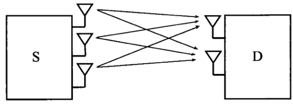
A single-user MIMO system consists of one antenna source and one multi-antenna destination as illustrated in Fig. 1.1. In 1999, Telatar proved the bene-lits of single-user MIMO systems by providing the channel capacity of a
mul-15 tiple antcnna system (Tclatar, 1999) based on information thcory. The givcn rcsults show the capability of the MIMO technology to cnhance the transmis-sion rate. Since that, MIMO technology attracted the attention of wircless com-munication rcscarch community. In the following, we analyzc the channel capa-city of MIMO point-ta-point system. The system consists of M-antenna source and N-antenna destination. At a time k, the source transmits a signal vector s[k]
=
(s[1,k],
s[2,k], ...
s[M,kJ)
T. Considering slow-fading, the signal madel can be cxprcsscd in vcctor form asy[k)
=
Hs[k]
+
n[k),
(1.10)whcrc
H
is N x M matrix of the fading channel coefficients and[Hlnm
= hnm is the channel coefficient of the link between the transmit antenna m and the receivcd antcnna n.n[k)
is an N x 1 Gaussian noise vector with identity covariance matrix (AWGN vcctor).ln (Tclatar, 1999), Tclatar dcrivcd the MIMO channel capacity for bath cases whcn the channel state is perfcctly known only at the destination and whcn the channel statc is pcrfcctly known at the source and at the destination. Considering that the channel statc is only availablc at the destination, MIMO channel capacity can be achicvcd by cqually distributing the transmit power ovcr the transmit antcnnas. The MIMO channel capacity is thcn writtcn as
C = log [ det
(lN
+
~
HH*)]
min(M,N) ( p )
=
~
log 1+
Ma} ,(1.11)
wh cre P is the source transmit power and { a1 , a2, ... , a min(M,N)} arc the eigen
va-lucs of H. If the channel statc is available at bath the source and the destination, the source should optimally distributc the transmit power P ovcr the transmit antcnnas. The optimal power distribution that maximizcs the rcliablc
comminu-16
tian rate can be obtained using the Waterfilling algorithm. The capacity formula becomes
C=
max (1.12)min(M,N)
L q,=M t=l
wherc q = {q1, q2 , . . . , qmin(M,N)} is the power fraction vector. The optimal values of q can be dcrivcd using the Lagrangian mcthod,
( M
)+
qi= 11- Pa} , \fiE {1, 2, ... , min(M, N)}, ( 1.13)
min(M,N) +
whcrc (a)+
=
max(O, a) and f1 is the solution of~
(11--/h)
=
M. Anyhow, it is challcnging to providc practical transmission techniques with ncar channel capacity performance and law complcxity.In general, MIMO schemes can be classified into two categories : a multiplcxing gain schcmcs and divcrsity gain schcmcs. The first spatial multiplcxing technique have becn proposcd in (Foschini, 1996) undcr the namc of Bell Laboratorics Laye-red Space-Timc" (BLAST). Sin cc that, Sc veral variants of BLAST have bccn dcvc-lopcd such us the vertical BLAST (VBLAST), the horizontal BLAST (HBLAST) and the diagonal BLAST (DBLAST).
The second catcgory of MIMO schcmcs aims to cnhancc the divcrsity and thus to rcducc the transmission crror probability. A diversity technique that attractcd a lot of attention is the space-timc black coding (STBC). The first STBC technique is proposcd in (Alamouti, 1998) and is namcd Almouti cncoding. The main objective is to provide a diversity arder cqual to two for a system with two-antcnna source and singlc-antcnna destination with CSI knowlcdgc only at the destination. This transmission technique is widcly used in severa! standards duc toits simplicity and cfficicncy. Severa! rcscarch groups have also becn intcrcsted in Alamouti cncoding technique and they cxtcndcd it to the case of (Tarokh ct al., 1999) wherc the
17
Figure 1.2: Multi-user MIMO system
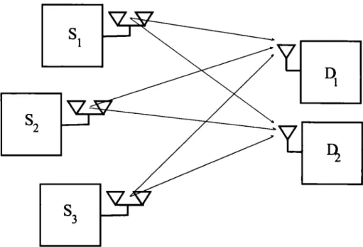
Alamouti coding is applied for transmittcrs with more than two antennas. Multi-uscr MIMO system
A multi-uscr system consists of multiple sources and multiple destinations as dc-pictcd in Fig. 1.2. MIMO tcchnology allows a multi-antcnna node to simulta-neously communicate with multiple users. We focus, in the following, on the two important multi-uscr systems namcly the multi-uscr acccss channel and the broad-cast channel. A multi-user acccss channel consists of multiple transmitters that communicatc with a single destination. When communications are donc on the reverse direction, i.e., from one source to multiple destination, the system is said to be broadcast channel.
18
callcd spacc-division multiple acccss (SOMA). The destination rcccivcs multiple lincar combinations of transmitted signais and bence it can gct frcc-intcrfcrcnce signais. Many works deal with multiplcxing gain of MAC channel. (Tsc ct al., 2004) shows that a MAC system, consisting of one N-antcnna destination and two sources with M1 and M2 antcnnas, has a multiplexing gain cqual to min ( M1
+
M2 ,N).
In (Jindal ct al., 2004), the authors dcfinc a duality bctwccn the MAC and the broadcast channcls (BCs). They show that the capacity region of the broadcast channel can be writtcn in tcnns of the capacity region of the MAC channel, and vice versa. As a rcsult, the multiplcxing gain of the broadcast channel is cqual to the one of the MAC channel. The two-user broadcast channel system, withM-antcnna source and two destinations cquippcd with ( N1 , N2) antcnnas, has a rnultiplcxing gain cqual to min
(M,
N1+
N2 ) (Yu and Cioffi, 2004),(Viswanath and Tsc, 2003). Whcn sufficicnt knowlcdgc of CSI arc availablc at the source, the latcst can pcrform the transmittcd signal in the dcsircd directions and null it out in the directions of othcr antcnnas or nades.1.2
Full-Duplex Radio
1.2.1
Main challenge in full-duplex transmission
During full-duplex transmission, the FD node rcceivcs its own transmittcd signal (self-interference) intcrfcrcd with the signal-of-intcrcst transmittcd by othcr dis-tant nades. As discusscd in the introduction, the key idca to makc full-duplex nades fcasiblc is to eliminatc the self-interference bcforc that the analog rcccivcd signal is samplcd by the ADC at the destination.
19
1.2.2
Self-interference mitigation
Sevcral groups in acadcmia and industry are intcrcsted to design and to impie-ment full-duplex radio. Prior works have made significant progrcss on the self-interference canccllation problcm. ln (Choi et al., 2010)-(Jain ct al., 2011), the authors design a new full-duplex radio. They propose analog and digital cancella-tion techniques that rcducc the self-interference power. Howcvcr, they providc at bcst 85dB of canccllation, which stillleave about 25dB of residual self-interference. Recent works show that multi-antcnna nades cao exploit space domain (spatial suppression) to eliminate the self-interference bcfore reaching the rcccivcd antcnna and thus to pcrform full-duplex transmission.
The idca bchind the spatial suppression is to bcamform the transmit signal such that it is orthogonal to the local received antenna direction which complctcly cli-minatc the self-interference. Different methods wcrc uscd for spatial suppression, sorne of them arc dcscribcd bclow. In (Surawccra ct al., 2013), the authors propose antenna selection technique to partially eliminatc the self-interference. The multi-antenna FD node selects the best reccivcr and transmit antcnnas combination in ordcr to produce the lowcst interference. In (Senaratne and Tellambura, 2011)-(Riihonen ct al., 2011), the authors showcd that FD nades cao completcly avoid the self-interference using null-space beamforming techniques. ln (Scnaratnc and Tcllambura, 2011), the authors showcd how a finite computational crror cao affect the FD transmission feasibility. A broad range of self-interference mitigation tech-niques, combining spatial proccssing, null-spacc bcamforming, and timc domain proccssing through a minimum mean square crror filtcring, have bccn investigated in (Riihoncn ct al., 2011). The authors showcd that self-interference cao also be eliminatcd whcn sidc information knowlcdgc is impcrfcct.
20
1.3
Relay Channel
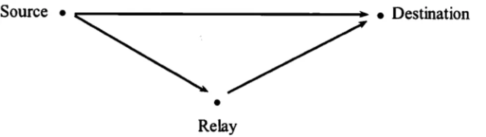
A relay is a wirelcss transccivcr that has the ability to rcccive a wirelcss signal from one node thcn to forward it toward anothcr node. ln general, a relay chan-nel consists of a source (S), a rclay (R) and a destination (D) as shawn in Fig. 1.3. The transmission proccss is pcrformcd in two phases. In the first phase, the source transmits a message to the relay. Thcn, the rclay proccsscs the rcccivcd signal and forwards it to the destination in the second phase. The message s trans-mittcd by the source is rcccivcd by bath the rclay (Yn) and the destination (y0 ).
The destination reccivcs a combination of the message transmittcd by the source (s) and the one transmittcd by the rclay (r). The rclay channel can be thcn rc-prcscntcd by a channel output y0 , the channel input s, the rclay's output Yn and
the relay's input r. The relay channel was first introduccd by Van Der Meulen in 1971 (Meulen, 1971). The author considcrs a rclay channel with ncgligiblc direct link (i.e., the link bctwccn S and D), callcd two-hop relay channel. Sincc thcn, relay channcls bccomc an intcrcsting subject in information thcorctic perspective for a long timc. Rclay channel capacity was cxtcnsively studicd. ln (Caver and Gamal, 1979), the authors dcvelopcd general strategies for rclay nctworks and pro-vided the rclay channel capacity with channel side information knowledgc. They dcfincd the dcgradcd relay channel as follows : "a relay channel is dcgradcd if f(Yo 1 s, r, Yn)
=
f(Yo 1 r, Yn),i.c., s--+ (r, Yn)--+ Yo fonn a Markov chain". Theycxamincd somc non-fadcd rclay channcls and they gave the capacity of the dcgra-dcd relay channel. Morcovcr, they prcscntcd an upper and lowcr bounds for the general rclay channel. In (Wang ct al., 2005), the authors studicd the capacity of MIMO rclay channel. They proposcd an algorithm to derive numcrically an upper bound and a lowcr bound for MIMO rclay channel capacity.
21 Source • ~~:::~---.
---t •
Destination•
Re layFigure 1.3: Relay channel
advantages. Relaying can be employcd to divert traffic from congcstcd arca of cellular systems to cclls with lowcr traffic load (Wu ct al., 2001). Thanks to relay channcls, ad-hoc nctworks provide higher network capacity proportional to the logarithm of the relay numbers (Gupta and Kumar, 2000)-(Gastpar and Vetterli, 2002).
Taking advantage of the broadcast nature of wireless channel and wireless multi-path propagation, the rclay channel can also enhance the transmission diversity (Sendonaris ct al., 2003). lndeed, the destination can take benefit from the relayed message copy propagated over multiple paths channel independent of the direct link channel (i.e., betwcen the source and the destination). The destination thcn may combine the rcdundant message copies which provides a diversity gain. The relay channel can be used to extend cell coverage (Pabst et al., 2004a)-(Host-Madsen and Zhang, 2005)-(Pabst et al., 2004b) and filling uncovered territories by forwarding the data signal to the areas on which the signal coming directly from the source cannot reach. AU in all, relay channels are efficient in power consumption, and they lead to higher throughput. Fig. 1.3 depicted the basic system model of a relay channel.
ln literature, several relaying algorithms have been proposed, called relaying stra-tegies. Each one has advantages and disadvantages ovcr the others. The most
22
common rclaying strategies arc arnplify-and-forward and dccodc-and-forward. - Amplify-and-forward (AF) : The rcccivcd signal by the rclay do not go
through the dccoding proccss. The relay simply amplifies the rcccivcd signal subjcct to rclay power constraint thcn it rctransmits the amplificd signal. The noise signal associatcd to the dcsircd signal is also amplificd, which cause noise power amplification. AF rcquircs low computational power and the shortcst pro-ccssing delay comparcd to the othcr rclaying strategies. Howcvcr, AF stratcgy is not efficient for multi-hop relay channel, duc to noise power amplification at cach rclay node.
- Decode-and-forward (DF) : The rclay decodes the rcccivcd signal bcforc retransmission and bence it rcquircs highcr proccssing delay thau AF. The re-lay givcs high SNR performance. It outpcrforms the othcr rcre-laying strategies (Lancman ct al., 2004). Thcrcforc, DF stratcgy is widcly prcfcrrcd.
1.4
Full-Duplex Relaying
As dcfincd abovc, a rclay is a transccivcr that has the ability to rcccivc a signal from a node and forward it to anothcr node. The dcploymcnt of a rclay that handlcs the two proccsscs simultancously or altcrnatc bctwccn them is the main difference bctwccn the FD and HD rclay channcls. In HD and FD rclay channcls, the samc frcqucncy band is uscd for bath transmissions from S ta R and from R to D. In HD rclay channel, different timc slots arc occupicd by cach transmission (Gatzianas ct al., 2007a) and bence the destination reccivcs two various copies, orthogonal in timc, of the samc signal. This providcs a divcrsity gain on the arder of two. Howcvcr, half of the timc spcnt on the communication proccss is wastcd in HD rclay channel. This rcsults in an incfficicnt spcctrum use. A full-duplex rclay node bas the ability to rcccivc and to transmit simultancously ovcr the samc
23
spcctrum band. Therefore, full-duplex rclaying is nccdcd to cnhance the system capacity and to improve the spectrum utilization cfficicncy .
Full-duplex rclay channel capacity was thoroughly analyzcd in (Caver and Gamal, 1979) under the assumption of no self-interference. The au thors provide the dcgra-dcd rclay channel capacity and also a general upper bound on the rclay channel capacity known as cut-set-bound. In (Simocns ct al., 2009), the authors consider a MIMO (multiple input multiple output) rclay channel and give upper and lower bounds of the capacity. Undcr the assumption of no self-interference, FD relay channel provides twice as much capacity as HD relay channcl(Riihonen et al., 2009). In all thosc works, a key assumption is that the relay operates in FD mode with no self-interference. This assumption is too strong sincc FD relaying is greatly affcctcd by relay self-interference. The self-interference should be climinatcd be-fore reaching the rcccived antenna. Thereforc the previous rcsults can be scen as capacity upper bounds ancl the FD rclay channel capacity should be recvaluated when a constraint on the reccived self-interference power is considercd.
HD relaying and FD relaying performances have bccn comparcd in (Riihoncn ct al., 2009)-(Kang and Cho, 2009), without considcring the cffcct of the direct link, showing that FD relaying achicvcs highcr end-to-end data rates. In FD rclay channel, the direct link between the source and the destination may not be ncgli-giblc and thcn the signal transmittcd by the source also acts, at the destination, as interference to the desircd signal transmittcd by the relay. In (Kwon et al., 2010), the authors showed the harmful effcct of the direct link interference problcm on the system outagc probability. They also showcd that, duc to this interference, FD rclaying only outpcrforms HD rclaying in high signal to interference ratio (SIR) of the relay link to the direct link. For this rcason, it is challcnging to providc a transmission schcmc that achicvcs the maximum mutual information in all SIR scenarios.
24
On the other band, it is well known that when the transmitter has channel side information (CSI), such as the channel state and its probability density function (PDF) knowledge, it can adapt the transmit power in time in arder to achieve capacity. ln (Goldsmith and Varaiya, 1997), the authors showed how to optimally distribute the transmission power in time to achieve the fading-channel capacity with channel state knowledge and long-term average power constraint. Optimal adaptive relay power allocation in time for amplify-and-forward HO relay chan-nel have also been studied in (Gatzianas ct al., 2007b)-(Rodrigucz ct al., 2013), rcspcctively. For a dccodc-and-forward FD rclay channel, the relay should adapt its transmit power in timc in arder to achicvc the maximum mutual information. Hcncc, the problcm of power allocation in timc should be addrcsscd in arder to find the optimal power distribution whcn the rclay has full CSI.
1.5
Notations
Throughout this thcsis, wc use R, S and D to denote relay, source and destination rcspcctivcly. 11.11 denotes the 2-norm,
[.JT
and[.J*
denote the transpose and the conjugatc transpose operators rcspectivcly. E[.] denotes the cxpcctation operator.1.1 denotes the modulus operator of the complcx number (.). hxF denotes the channel coefficient bctwccn two antennas X and Y, '/'XF = lhxFI2 and 1xy =
Ebxrl
The argument of a complex numbcr is dcnotcd by arg(.). [x]+ denotes max(O, x). The PDF of a random variable x is dcnotcd by f(x ).ct
"t' (rcspectively,I{y) denotes the channel capacity (respectivcly, maximum mutual information) whcn instantancous CSI is available at the node X and Y. c~-D denotes the channel capacity when instantancous CSI of R-D link is available at R.
CHAPTER II
ON THE PERFORMANCE OF FULL-DUPLEX RELAY
CHANNEL UNDER THE CONSTRAINT OF NULL
SELF -INTERFERENCE POWER
Full-duplex transmission is feasible only through self-interference avoidance, be-fore rcaching the ADC at the front-end of the reccivcd antenna. ln arder to grant fcasibility, a constraint on the rcccived self-interference power have to be imposcd on the full-duplex node and this constraint should be considcrcd in analyzing the full-duplex relay channel capacity. The channel capacity is often studicd undcr transmit power constraints. The channel capacity undcr rcccivc power constraints was introduccd in (Gastpar, 2007). Our contribution in this chaptcr is to provide an cxplicit form of FD degradcd rclay channel capacity under the constraint of null receivcd self-interference power. Bascd on this rcsult, wc derive the maxi-mum mutual information expression for the FD relay channel with the important dccodc-and-forward stratcgy and instantancous CSI at the rclay. Wc provide that the maximum mutual information of FD rclay channel is twicc the one of HD rclay channel with singlc-antcnna rclay whcn the channel coefficients follows Rayleigh distribution.
The contents of this chapter have bccn submittcd for publication in IEEE Tran-saction on Wirclcss Communication (TWC) (Chraiti ct al., 2014a).
26
2.1
System Model
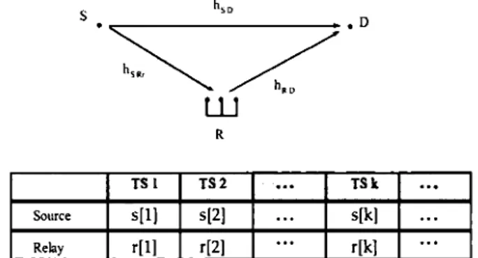
Wc considcr a classical relay dcgradcd channel models which consists of one singlc-antcnna transmit ter, one singlc-singlc-antcnna destination and one relay. The rclay takcs advantage of MIMO tcchnology to control the rcccivcd self-interference power which typically rcquircs two transmit antcnnas (Rtt and Rt2) more than the re-cci v cd antcnna ( Rr). The ti mc is di vidcd in fixcd-sizc ti mc slots ( dcnotcd by TS). The TS size is small cnough so that the channel stays constant within a TS but varies indcpcndcntly from TS to anothcr. Fig. 2.1 shows the rclaying system consi-dcrcd in this papcr, whcrc s[k] and r[k] capture the source and the relay complcx Gaussian inputs rcspcctively, during kth TS. The rclay and the source transmittcd signais arc subject to an instantaneous power constraints Pn and Ps respcctively.
R
TS 1 TS2
...
TSk...
Source s[l) s[2)
...
s[k]...
Re lay r[l] r[2)
...
r[k]...
Figure 2.1: Full duplex transmission proccss
2.1.1
Signal model
At a givcn TS (when not rcquircd, the TS index k is dropped), S transmits a codcword s whilc the rclay transmits a codcword r which is depends on the prc-viously received signais from the source. The relay may use a MIMO prccoding
27
technique to control the self-interference. The rcccivcd signais at the relay and at the destination cao theo be writtcn as
Yn = ffshsnrs
+
ffnhn.w*r+
nn YD = ffnhnv.w*r+
ffshsvs+
nv,(2.1)
(2.2)
whcrc hn
= (
hnnRr, hn,2Rr,), hnv= (
hnnD, hn,2v) and w is a precoding vector uscd to control the rcccivcd self-interference power. nn and nv arc the AWGN at Rand D rcspcctively. A part of the noise nn depends on the rcccivcd self-interference power. Without loss of gcncrality, nn is also assumcd AWGN with unit variance whcnRr
does not rcccivc any self-interference signal.2.1.2
Self-interference pre-nulling
The relay cao complctcly climinate the self-interference when perfcct CSI is avai-lable at the rclay (Riihoncn ct al., 2010), t.e., the relay rcceivcd antcnna rcceives null self-interference power. Indccd, the rclay cao bcamform the transmittcd si-gnal in the dcsircd direction and null it out on rclay rcccivcd antcnna direction. A simple bcamforming technique cao be uscd such as zero forcing bcamforming. ln this case, the signal reccivcd by the relay is writtcn as
(2.3)
2.2
Performance Analysis Under Null Received Self-Interference
Power Constraint
In the following, wc derive an cxplicit form of the channel capacity for FD dcgra-dcd rclay channel capacity, undcr the constraint of null rcccivcd self-interference power. Based on the capacity formula, wc theo derive an cxplicit form of the
28
maximum mutual information for a FD dccodc-and-forward relay channel with instantancous CSI availablc only at the rclay. Wc obviously assume that the chan-nel statc of S-D and R-D links is known at the destination. The system is subjcct to transmit power constraints (Pn and Ps ) and a rcccivc power constraint (null self-interference power).
2.2.1
Capacity analysis
Wc considcr an FD dcgradcd relay channel with instantancous CSI at the source and the relay. Dcgradcd relay channel was studicd in (Caver and Gamal, 1979) considcring just channel input constraints,i.c., the source and the rclay transmis-sions arc subjcct to transmit power constraints. The authors cxamincd non-fadcd rclay channels and they gave the capacity of the dcgradcd relay channel whcn S, Rand D arc singlc-antcnna nades. From [Thcorcm 1, (Caver and Gamal, 1979)], the general form of the FD dcgradcd rclay channel capacity, with instantancous CSI at the source and the relay, is writtcn as
C}g n(l)
=
max min (/(s; Ynir), l(s, r; Yo)).' O~f(s,r)~l (2.4)
whcrc f(s, r) is the joint probability of s and r. Wc denote f(s, r) by J. Undcr transmit signal power constraint, the capacity obtaincd in (2.4) bccomcs
C8 1
n(1) = max min (log (1
+
Ps(l- !3hsn),' O~(l~l r
log ( 1
+
Ps~so
+Pnb
nol'+
2},3Ps~soPnl~nol')).
(2.::>)
ln arder to
p~cscnt
the ncxt thcorcm, wc(p~c~~:~ t:cR,~~)dccompo(si~~n o~
th)c channel matnx as H=
GQ, whcrc H=
,
G=
hnnD hn,2D G2 GQR is a C2x2 lowcr triangle matrix and
Q
is a unitary matrix. It is to be highlightcd29 the rcccived self-interference power in addition to the constraint on the transmit power, whercas the formula obtaincd in (2.4) considers only a constraint on the transmit signal power.
Theorem 1. Considering that the source and the relay have instantaneous CS!, for a given channel realization, the channel capacity of the FD degraded relay
channel under null received self-interference power constraint can be written as
C~
n(l) = max min (log(1
+
Ps(l- f3hsnr),' O<St:i<:::;l
log ( 1
+
Pnsv+
PniGQnl'+
2Jli
Ps7svPniGqnl2 ) ) .(2.6)
Démonstration. To provc (2.6), wc first provc that the capacity is higher or equal than the explicit form given in (2.6) and second we provc that it is lower or equal. First, let us consider the relay precodcd technique, based on QR decomposition, defined by the following precoded signal
(2.7)
where P is the rclay power allocation matrix and r1 and r2 denote the two
code-words transmitted to R,. and D, respectively. Espccially, whcn P =
(O
0 ) 0ffn
and r2 = r, the reccived signais by Rr and D from the relay transmit antennas30
(R11 and R12 ), in noiselcss cnvironmcnt, arc as follows
( YYRDr) = H x u
(2.8) The QR decomposition with thcse prcvious paramctcrs allow the relay to com-plctely eliminatc the self-interference and thus to satisfy the constraint of null . rcccivcd self-interference power. Wc gct the following incquality
max min (log
(1
+
Ps(1- /3hsnr), log(1
+
Ps'"YsD+
O:Si3:Sl
PlliGQRI2
+
2J ,JPs~svPRI
GQnl2) ) <;
C~
.• (l)'which follows from the definition of the capacity obtaincd in (2.4).
(2.9)
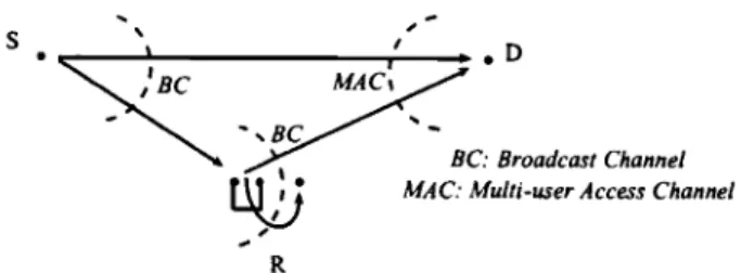
Ncxt, to provc the incquality in the reverse direction, a key stcp is to trcat the transmission system formcd by the relay and the destination as a broadcast chan-nel system with two singlc-antcnna rcccivcrs {Rn D} and a two-antcnna transmit-ter (Rtl, R12 ) as shawn in Fig. 2.2. The link bctwccn the two-antcnna transmit ter
and
Rr
(rcsp. D) will be dcnotcd the link R-Rr (rcsp. R-D).The capacity region of the MIMO broadcast channel is providcd in (Wcingartcn ct al., 2006). The authors showcd that dirty papcr coding (DPC) region coïncides with the capacity region. In the case of a two-antcnna transmittcr and two singlc-antcnna uscrs, a transmission schcmc that achicvcs capacity has bccn proposcd in (Caire and Shamai, 2001). lt is dcnotcd by modificd rankcd known interference. This transmission schcmc is bascd on the QR technique, DPC technique and power
' s '
"'SJ(
~,acnG
,~ R BC: Broadcast Channel MAC: Mu/ti-user Access ChannelFigure 2.2: Full duplex rclay system
allocation. The for rn of the precodcd signal is u
~
Q" (
~
rcsulting two rcccivcd signais are31
(2.10)
(2.11)
The signais r1 and r2 arc dcstincd to Rr and D rcspcctivcly. Using the coding
for known interference technique, the destination is able to decode r2 as if the
interference signal ..;p;;G2r1 is not present (Caire and Shamai, 2003). Let a1 and
a2 denote two positive real variables. At a givcn transmit power matrix and fixcd values of a1 and a2, the mutual information of links R-Rr and R-D arc (Caire and Shamai, 2003)
(2.12) (2.13)
The capacity of the broadcast channel is obtaincd by solving the following opti-mization problcm (Caire and Shamai, 2003)
32 maxim ize P,a1,a2 s.t (2.14a) (2.14b) (2.14c) From (2.13) and (2.10), Rr rcccivcs a dcsircd signal and an interference signal. Considcring the constraint of null rcccivcd self-interference imposcd on the rclay (i.e., null out bath signais on Rr direction), wc add the following two constraints to the optimization problcm in (2.14),
(2.15) Obviously, the channel gains in (2.15) arc strictly grcatcr thau wro. Thcrcforc, Pma2 = 0 and Pma1 = O. Hcncc, the optimization problcm obtaincd in (2.14)
bccomcs
s.t
(2.16a) (2.16b) (2.16c) The optimal solution, Pn2a2 = Pn, is trivial to obtain. Thcn, the capacity of the broadcast channel bctwccn the transmit antcnnas ofR (Rt1 and Rt2) and D, undcr null rcccivcd self-interference power constraint, is the channel capacity of the link R-D which is writtcn as
(2.17) It is important to note that the capacity in (2.17) cau be achicvcd by using the QR decomposition and power allocation. Considcring the null rcccivcd self-interference
33 power and transmit power constraints, the channel capacity of the R-D link is obtaincd by C8 in (2.17) which is equivalent to the capacity of a Gaussian
single-user system with no rcccivcd power constraint whcn the channel coefficient is cqual
to GQR· The system bccomcs equivalent to a relay channel with singlc-antcnna
rclay and with no self-interference whcrc the channel coefficient bctwecn the rclay and the destination is cqual to GQR· Form (Caver and Gamal, 1979), wc get an
upper bound of the relay channel capacity undcr the constraint of null receivcd self-interference power
c~
R{1)~
max min (log (1+
Ps(1- f3hsRr)'' 0:'::,139
log ( 1
+
Pnso
+
Pni~RDI
2
+
2)fJPs~soPni~RDI'))
{2.18)
From incqualitics {2.9) and (2.18), one cao find (2.6). This completes the proof. 0
Note that the prcvious rcsults are obtained assuming that the signal is always transmittcd via the direct and relay links. Howcver, whcn the channel gain of the direct link is bctter than the one of the relay link, it is optimal for the relay to not rclay signais. In this case, the abovc capacity rcduccs dawn to the capacity of the direct channel bctwccn the source and the destination. The capacity of this systems cao theo be cxprcsscd as
c~.R =max (log (1
+
Ps'YSRr), c~.R{1)). (2.19)Wc will now derive the FD dcgradcd relay channel capacity, undcr the constraint of null rcccivcd self-interference, for the case whcrc statc of channcls is not availablc at the source. Morcovcr, wc considcr that the rclay has only knowlcdgc of the channel state of the R-D link but not the channel statc of the S-D link. This
34
rcsult is crucial to derive, in the ncxt subscction, the cxplicit fonn of the maximum mutual information of FD rclaying with the dccodc-and-forward stratcgy.
Theorem 2. Considering that the rclay has CS! of R-D link but not the CS! of the S-D link, the channel capacity of the FD degraded relay channel under the constraint of null received self-interference can be written as
c~-D =min (log (1
+
Ps"/SRr) 'log (1+
Ps"/SD+
PnlGQnl2) ) . (2.20)Démonstration. Wc nccd to provc that whcn the CSI of the direct link is not availablc to the rclay, the capacity is obtaincd by (2.6) with
f3
= 0, i.e., rand sarc indcpcndcnt.
Wc denote by y~ the rcccivcd signal by the destination multiplicd with the factor h'
.::..il2..._
ihsDI'
(2.21)
whcrc () = arg(h'SDGQn) and n~ =
1
~!~1
nD. The channel statc of the link S-D is unknown at the source and at the rclay, thcn () is a random variable uniformly distributcd in [0, 21r[. The channel capacity is thcn writtcn asc~-D
= max min (I(s; Ynlr), Eo[I(s, r;y~
JO)J) .
0::01:1::0 1
The second tcnn of the min function in (2.22) is dcvclopcd in (2.23).
35 Eo[I(s, r; y~ 1 0)] =log ( 1
+
Es,r,li[Y~(y~)*J)
=log (1+
(lhsvl IGQnl) ( Ps . JPsPn/3Eo[&
8] =log (1+
Pslhsvl2+
PniGQnl2). (2.23)lt is bence indepcndcnt of (3. Morcovcr, the first tcrm /(s; Yvlr) = log(1
+
Ps(1-;3)1hsvl2) is maximum for/3
= 0 (i.e., sand r arc indcpcndcnt). Thus, the capacity is achicvcd whcn the source transmits a codeword s independent of the codeword r transmittcd by the relay. This completes the proof. 02.2.2
Maximum Mutual Information Analysis
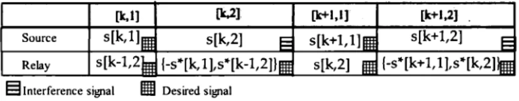
In this subsection, wc consider that instantancous CSI knowledge is only available at the rclay. At a givcn timc slot (kth TS), the source transmits a new codcword, independcnt of the prcvious transmittcd codewords. Simultaneously, the decodc-and-forward FD relay decodes the kth source codeword and transmits an estimatcd codcword from the signal rcccived during the prcvious TS ((k- 1)lh TS). The maximum mutual information is given in the following theorem.
Theorem 3. Considering that the relay has instantaneous CS/, for a given
chan-nel realization, the maximum mutual information of a decode-and-forward FD
relay channel under null received self-interference power constraint can be written as