HAL Id: hal-02510793
https://hal.archives-ouvertes.fr/hal-02510793
Submitted on 18 Mar 2020
HAL is a multi-disciplinary open access
archive for the deposit and dissemination of
sci-entific research documents, whether they are
pub-lished or not. The documents may come from
teaching and research institutions in France or
abroad, or from public or private research centers.
L’archive ouverte pluridisciplinaire HAL, est
destinée au dépôt et à la diffusion de documents
scientifiques de niveau recherche, publiés ou non,
émanant des établissements d’enseignement et de
recherche français ou étrangers, des laboratoires
publics ou privés.
Analysis and Control of Non-Minimum Phase Behavior
in Nonlinear AC Grids Equipped with HVDC Links
Yankai Xing, Mohammad Pourmahmood Aghababa, Bogdan Marinescu,
Florent Xavier
To cite this version:
Yankai Xing, Mohammad Pourmahmood Aghababa, Bogdan Marinescu, Florent Xavier. Analysis
and Control of Non-Minimum Phase Behavior in Nonlinear AC Grids Equipped with HVDC Links.
2019 IEEE PES Innovative Smart Grid Technologies Europe (ISGT-Europe), Sep 2019, Bucharest,
Romania. pp.1-5, �10.1109/ISGTEurope.2019.8905703�. �hal-02510793�
Analysis and Control of Non-Minimum Phase
Behavior in Nonlinear AC Grids Equipped with
HVDC Links
Yankai Xing, Mohammad Pourmahmood Aghababa, Bogdan Marinescu
Ecole Centrale de Nantes LS2N-CNRS Nantes, France
{Yankai.Xing, Mohammad.Pourmahmood-aghababa, Bogdan.Marinescu}@ec-nantes.fr
Florent Xavier
RTE R&D Division Paris La Defense, France Florent.Xavier@rte-france.com
Abstract—It is known that non-minimum phase zeros (NMPZ) can degrade the performance of the control systems. Especially, NMPZs bring some delays to the system making the system to be unstable in large gains. In this article, the aim is to recognize the existence of NMPZs in high voltage direct current (HVDC) lines imbedded into AC grids and to develop a method to cancel out their effects. Subsequently, the process on two real power grids with two different HVDC models are examined to detect the possible NMPZs in their dynamics. Accomplishing linear and nonlinear simulations in Matlab and Eurostag, the location of unstable zeros are determined. Then, a benchmark model is adopted to identify the affecting parameters of the power system on the occurrence of the NMPZs. The analysis concludes that the NMPZs can appear in the system as short-circuit power at connection points of HVDC line and generators. Finally, to avoid the harmful effects of theses NMPZs, a modified zero phase error compensator (MZPEC) is proposed, which is noise insensitive in the control loop. Simulation results reveal that the use of the provided MZPEC along with a classic power oscillation damping (POD) controller can greatly improve the action of the POD and, therefore, can increase the power transfer quality of the grid.
Index Terms—Non-minimum phase zero, High voltage direct current link, Power network, Damping controller, Zero phase error compensator
I. INTRODUCTION
Nowadays, transmission grids are reinforced by high voltage direct current (HVDC) lines which have also the capacity to damp inter-area oscillations. For that, HVDCs are equipped with some power oscillation damping (POD) controllers to modulate the active and reactive power to bring more damping features for the grid [1]. Several useful applications of PODs for HVDC links have been reported in the literature. In [2], the authors have designed an optimal POD for power grids. In another work [3], the application of H∞ robust control
has been demonstrated for inter-area modes damping. In [4], a fuzzy logic POD has been proposed for a power system. The research [5] has derived a nonlinear control methodology for cancelling out the effects of the oscillations in electricity network with HVDCs. Although, these advanced controllers
have shown good performances, they may be affected by some unstable zeros in the open-loop system.
It is well-known that non-minimum phase zeros (NMPZ) bring some delays in the outputs of the system [6]. Also, con-trol community has recognized that the existence of NMPZs can destabilize the closed-loop system in high gains [7]. The appearance of NMPZs in HVDC links has been reported in the literatures [8]. However, there is a little work about why and how the NMPZs appear in the HVDC links inserted into a meshed AC grid. As a consequence, it is important in both research and practice to do analysis on the parameters of the grids with HVDC links to highlight their effects on the NMPZs which is the first objective of this research. The second goal of this work is to design a co-compensator along the existing PODs to suppress the NMPZs improving the stability of the power grid or at least preserving the nominal POD behavior.
In this paper, the sensitivity analysis of NMPZs is done on two real power grids. They model realistic zones of the European electricity network which have been installed with HVDC links. Two different HVDC models are used in these grids. The results show the connections of NMPZs to the networks. To accomplish the examination, investigation of the existence of NMPZs in a benchmark power system equipped with a HVDC link, which can reproduce all the AC grid, is car-ried out. This investigation shows that under some situations, this power system exhibits non-minimum phase behavior. The most important parameters that determine the existence or non-existence of NMPZs are found as short-circuit power at connection points in both situations for HVDC and generators. This means that the NMPZs depend on the topology of the network. Since the traditional zero phase error tracking control (ZPETC) [9] aims to track the command signal, they put the characteristic equation of the system followed by the mirror of system unstable zeros in the numerator of their transfer functions. Thus, an improper transfer function is generally resulted for the structure of the standard ZPETC. However, it is well known that improper transfer functions are very sensitive to the noises and external disturbances. Furthermore, such improper expressions should be implemented by a series
of derivative blocks which is quite hard to be achieved in practice. To overcome this problem, a modified zero phase error compensator (MZPEC) as a supplementary feed-forward controller to the POD controller is proposed to decrease the non-minimum phase behavior of the system responses. In order to verify the effectiveness of the MZPEC, a classic POD (i.e., vector control [10]) is selected as an example in this paper. Simulations in both Matlab and Eurostag for step responses indicate that the use of a MZPEC can greatly improve the removal of non-minimum phase behavior in both linear and nonlinear results. Thus, it would be a promising method to increase the quality of power transfer in power grids.
The paper is organized as follows: in Section II the NMPZs are analyzed in the case studies. The control problem is formulated in Section III. The proposed feed-forward con-troller framework is given in Section IV. Computer simulation results are illustrated in Section V. Section VI is devoted to conclusions and perspectives of this work.
II. PROBLEM STATEMENT
In this section, first two motivating realistic examples are given. Next the NMPZs are more supplementally studied on a benchmark which can reproduce all AC grid connection situations.
A. HVDC models
Fig. 1 depicts the considered voltage source converter (VSC) - HVDC. The high-frequency switching operation of the power electronics is neglected, and each converter is modeled as an injector (current or power). Two degrees of detail are considered here: first one, called model 1, in the sequel, consists of the harmonized EMT and transient model of injections [11]. The second one called model 2 in what follows, is a simplification of the first one in order to capture only lower frequency behavior for transient dynamics. Then, the voltage source whose magnitude Uac and phase angle θ
can be controlled. P1, P2 and Q1, Q2 are active and reactive
powers exchanged with the power system respectively.
Fig. 1. HVDC model.
B. Description of power grids
Two power grid models along with HVDCs to investigate the accuracy of NMPZs in their structure are adopted here.
Case 1 is the same large-scale system as in papers [2] and [3], which is a power system with 19 generators and one HVDC line. All generators are equipped with AVR (Automatic Voltage Regulator) and PSS (Power System Stabilizer). The nonlinear model of this system, which is of order 724, is linearized around an equilibrium point with Eurostag software to obtain the linear model of the same order.
To examine more deeply the existence of NMPZs in practi-cal power grids, another test named case 2 on the France-Spain network (Fig. 2) which is presented in [12] is done to detect the possible NMPZs. This system consists of 23 machines. The system is represented by a detailed nonlinear model including generators along with their regulations. Only the high-voltage network 225 kV and 400 kV are modeled. The interconnection between France and Spain, which consists of four AC lines, is reinforced by adding a VSC-based HVDC link of 65-km length with a nominal active power of 1000 MW and a rated pole voltage of 320 kV.
Fig. 3 shows an equivalent schematic diagram for the above-mentioned cases.
Fig. 2. France to Spain network.
Fig. 3. HVDC inserted into a AC grid.
To check the existence of NMPZs in the grids, first, HVDC converter is equipped with a POD. The input signal to POD controller is very important. According to [13], the latter are chosen to provide the highest residue of the oscillatory mode to be damped in the open-loop for the transfer function to POD. Difference of two terminal angles ∆θ = θ1− θ2 is selected
for both case 1 and 2. NMPZs are found in the linearized open-loop system without any PODs for both P and Q power modulation as shown in Table I.
TABLE I
NMPZRESPONSES IN OPEN-LOOP SYSTEMS
Cases behavior (Q modulation)NMPZs/Non-minimum behavior (P modulation)NMPZs/Non-minimum CaseI+HVDC modelI Yes/Yes Yes/Yes CaseI+HVDC modelII Yes/Yes No/No CaseII+HVDC modelII Yes/Yes No/No
Cases in Table I show the combinations of different types of AC grid and different HVDC models. Non-minimum phase behavior in Table I is detected in nonlinear responses in accordance to this fact that in the case of NMPZs, at the opposite direction of the final value [6]. Each case in this table has this behavior. For instance, Fig. 4 shows the response of a step on Q modulation for CaseI+modelII. The curve goes to the opposite direction at 2 sec compared with the final value. From Table I, NMPZs are coherent with non-minimum phase behavior in curves which confirms the existence of NMPZs of the system. Another conclusion can be made that no-matter the model of HVDC line, this phenomena appears in the system.
Fig. 4. Difference of angle response of a step on Q for CaseI+modelII.
C. Systematic analysis with a benchmark model
To investigate the relationship of NMPZs to the components of grid, a benchmark in Fig. 5 according to [13] is used in this paper. In this benchmark, there are two generators, one HVDC line, 5 AC lines and 5 nodes with one load. HVDC model here is a simple injector model. One can switch from a structure to another one by a simple change of the parameters. For instance, if the impedances of all the transmission lines changed, the unstable zeros will change for each cases. In Table II, 6 cases are investigated by modifying the length of lines. Notice that topology in Fig. 5 covers all HVDC AC grid connections scenarios.
Table II lists the analysis results. Unstable zeros in the list are obtained in transfer function from Q modulation to ∆θ. It is concluded that the most affecting parameters of the model on existence of NMPZs are impedances of lines. This means that the distance from the generators is the most important factor for the location of system zeros.
Fig. 5. Benchmark system.
III. THEPODAND THE IMPACT OF UNSTABLE ZEROS
The existence of NMPZs in the open-loop system, the effec-tiveness of POD can be decreased even with some advanced controls which is due to un-modifying unstable zeros in the closed-loop scheme. In previous work [2], this phenomenon has been verified on the results. In order to describe the impact of unstable zeros to the POD, an example (classic POD) application is investigated in this section.
The classic IEEE HVDC POD controller has the same structure as the PSS for generators, which contains a gain K, a wash-out filter and n phase lead-lag blocks (Fig. 6). It is easily to tune it to damp one specified mode [10].
Fig. 6. The structure of classic POD.
Due to the lack of space, we do not present all the cases studied. An example case (caseI+HVDC modelI) which is same model with previous work is selected to show. The parameters of classic POD is tuned to damp the mode 2 of to 10 %. From Fig. 9 (curves of ∆θ respond to steps on Q modulation in linearized system) and Table III, although the damping of modes are improved a little, the desired damping is not achieved because of non-minimum phase effect. Moreover, at 2 sec, curves have an overshoot which is a delay actually. With this kind of delay, the POD controller may lose efficacy. Thus, it can be summarized that the HVDC link inserted in AC grid brings some unstable zeros which disturb the POD controller performance in the grid. So that, a solution should be developed to overcome the influence of the unstable zeros.
IV. FEED-FORWARD ZERO PHASE ERROR CONTROLLER
In this section, after reviewing the original ZPETC method, a modified ZPEC is proposed to enhance the performance of the standard ZPETC in dealing with NMPZs.
TABLE II
RESULTS OF ANALYZING THE BENCHMARK SYSTEM
No. of case length of L1 length of L2 length of L3 length of L4 length of L5 unstable zeros
case 1 25 25 300 25 25 No case 2 100 25 300 25 25 Yes case 3 25 40 300 25 25 Yes case 4 25 25 100 25 25 No case 5 25 25 300 100 25 Yes case 6 25 25 300 25 100 Yes TABLE III
COMPARISON OF DAMPING OF MODES
No.mode Damping withoutPOD (%) with classic POD (%)Damping of modes
1 19.5 30.5 2 4.5 6.1 3 10.1 12.0 4 8.3 8.1 5 10.1 12.4 A. Original ZPETC
ZPETC is a controller which reduces the phase error caused by the unstable zero dynamics. Let us consider a transfer function expressed in continuous-time domain [14].
y(s) r(s) = N (s) D(s), (1) where, D(s) = a0+ a1s + a2s2+ ... + ansn N (s) = b0+ b1s + b2s2+ ... + bmsm, (n ≥ m). (2) For a non-minimum phase system, N (s) can be split into two parts as follows,
N (s) = Na(s)Nu(s), (3) where, Na(s) represents the stable zeros, Nu(s) stands for
unstable zeros. The original ZPETC can be designed as the following form [9],
ZP ET C = D(s)N
u(−s)
Na(s)[Nu(0)]2, (4)
which makes the transfer function of overall is yd
yd∗ =
Nu(−s)Nu(s)
[Nu(0)]2 . (5)
With this feed-forward controller, the transfer between ydand
y∗
d in Fig. 7 will have no phase shift for all frequencies. To
demonstrate this fact, one has, Nu(−s)| jω= Re(Nu(jω)) − jIm(Nu(jω)) Nu(s)| jω = Re(Nu(jω)) + jIm(Nu(jω)). (6) So that, Nu(−s)Nu(s)|jω= Re2(Nu(jω)) + Im2(Nu(jω)) = |Nu(jω)|2. (7) Equation (7) shows that the transfer function between y(s) and y∗(s) does not have imaginary part, which means no phase shift at all.
Fig. 7. Block diagram of the original ZPETC.
B. Modified ZPEC
According to Fig. 7, it is revealed that the original ZPETC removes the closed-loop system poles by applying 1/D(s). On the other hand, in both case 1 and case 2, the systems contain high number of states. This makes the original ZPETC cannot be directly applied. Due to the high degree of D(s) and since the goal is not to cancel out the effects of D(s), the original ZPETC (4) is revised as given in Fig. 8. Since the aim is to compensate the unstable zeros, this controller can be designed as a low-order structure called modified ZPEC. It is noted that the improper transfer functions simulate the behavior of derivatives and can thus result in a noise-sensitive system. As a consequence, some other real poles (D0(s)) are added to obtain a proper compensator. The final degree of D0(s) is greater or equal to the number of unstable zeros. So, the proposed MZPEC is less complex compared to the standard ZPETC that uses D(s). The locations of the poles in D0(s) are chosen quite far from the dominant poles of the original closed-loop system. And D0(0)2is added in numerator to cancel the gain brought by this term.
Fig. 8. MZPEC feed-forward controller for the closed-loop system.
V. SIMULATIONRESULTS
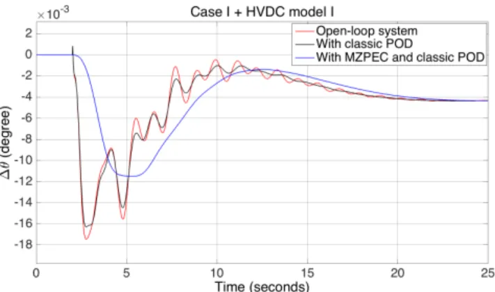
Here, the proposed POD-MZPEC is implemented for both linearized and nonlinear power networks of caseI+HVDC modelI. The applied control scheme is described in Fig. 8. A. Linear simulations
With a step disturbance on Q in linear system, ∆θ responses are shown in Fig. 9. It can be seen that with MZPEC, non-minimum phase behavior is eliminated with less undershoot
and the classic POD can reach the desired damping in this case. It is noticed the fact that more smooth curve in ∆θ, less oscillation can be seen both in HVDC line and in the speed of generators.
Fig. 9. Step responses of the linear system.
B. Nonlinear simulations
Here, nonlinear simulations are carried out with Eurostag software. From these results, the improvement of POD-MZPEC controller is clearly shown in Fig. 10.
Fig. 10. Step responses of the nonlinear system.
VI. CONCLUSIONS AND PERSPECTIVES
This paper was concerned on the non-minimum phase behavior of electrical networks equipped with POD controlled HVDC links. Since the existence of non-minimum phase zeros lessens the stability characteristics and, therefore, the power transfer quality of the electric grids, much more attention should be paid to how to decrease these harmful effects. So, after rigorous analysis of the participation of system compo-nents in the zero placement of the network, the fact found is that the physical components, such as the short-circuit power at the connection points of the HVDC, can bring out unstable zeros. Subsequently, a modified zero phase error compensator was proposed to handle the grid unstable zeros. The simulation results on a real power grid equipped with a POD controller
along with the suggested co-compensator MZPEC indicate that the non-minimum phase behavior of both linearized and nonlinear network models was effectively suppressed. Also, the introduced MZPEC is free of the controller type applied and it can be implemented on some advanced POD controllers (i.e., linear quadratic gaussian (LQG) or H∞) to cancel this
kind of unstable zeros delays to perfect the dynamic responses. Thus, it can be concluded that the results of this research have the merits to be implemented in real world electric grids to increase the stability margin and power quality.
The future work along this research will be devoted to do analysis on the hierarchical implementation of active and reactive power modulation for obtaining further improvement in the responses.
ACKNOWLEDGMENT
The authors would like to thank China Scholarship Council (CSC) for the financial support to Yankai Xing.
REFERENCES
[1] H. F. Latorre, M. Ghandhari, and L. S¨oder, “Active and reactive power control of a vsc-hvdc,” Electric Power Systems Research, vol. 78, no. 10, pp. 1756–1763, 2008.
[2] Y. Xing, B. Marinescu, M. Belhocine, and F. Xavier, “Power oscillations damping controller for hvdc inserted in meshed ac grids,” in Innovative Smart Grid Technologies Conference Europe (ISGT-Europe), 2018 IEEE PES. IEEE, 2018.
[3] Y. Xing, B. Marinescu, and F. Xavier, “Robust research of power oscillations damping controller for hvdc inserted in meshed ac grids,” in PowerTech, 2019 IEEE PES. IEEE, in press.
[4] M. Bakhshi, M. H. Holakooie, and A. Rabiee, “Fuzzy based damping controller for tcsc using local measurements to enhance transient sta-bility of power systems,” International Journal of Electrical Power & Energy Systems, vol. 85, pp. 12–21, 2017.
[5] K. Liao, Z. He, Y. Xu, G. Chen, Z. Y. Dong, and K. P. Wong, “A sliding mode based damping control of dfig for interarea power oscillations,” IEEE Transactions on Sustainable Energy, vol. 8, no. 1, pp. 258–267, 2017.
[6] J. B. Hoagg and D. S. Bernstein, “Nonminimum-phase zeros-much to do about nothing-classical control-revisited part ii,” IEEE Control Systems Magazine, vol. 27, no. 3, pp. 45–57, 2007.
[7] K. Zhou and J. C. Doyle, Essentials of robust control. Prentice hall Upper Saddle River, NJ, 1998, vol. 104.
[8] L. Zhang, L. Harnefors, and H.-P. Nee, “Interconnection of two very weak ac systems by vsc-hvdc links using power-synchronization con-trol,” IEEE transactions on power systems, vol. 26, no. 1, pp. 344–355, 2011.
[9] M. Tomizuka, “Zero phase error tracking algorithm for digital control,” Journal of Dynamic Systems, Measurement, and Control, vol. 109, no. 1, pp. 65–68, 1987.
[10] “IEEE recommended practice for excitation system models for power system stability studies (ieee std 421.5-2005),” Energy Development and Power Generating Committee of the Power Engineering Society, vol. 95, p. 96, 2005.
[11] B. Meyer and M. Stubbe, “Eurostag, a single tool for power system simulation,” Transmission and Distribution International, vol. 3, no. 1, pp. 47–52, 1992.
[12] L. Arioua and B. Marinescu, “Robust grid-oriented control of high voltage dc links embedded in an ac transmission system,” International Journal of Robust and Nonlinear Control, vol. 26, no. 9, pp. 1944–1961, 2016.
[13] M. Belhocine, B. Marinescu, and F. Xavier, “Input signal and model structure analysis for the hvdc link pod control,” in PowerTech, 2017 IEEE Manchester. IEEE, 2017, pp. 1–6.
[14] H.-S. Park, P. H. Chang, and D. Y. Lee, “Continuous zero phase error tracking controller with gain error compensation,” in Proceedings of the 1999 American Control Conference (Cat. No. 99CH36251), vol. 5. IEEE, 1999, pp. 3554–3558.