HAL Id: hal-01819024
https://hal.archives-ouvertes.fr/hal-01819024
Submitted on 8 Nov 2019
HAL is a multi-disciplinary open access
archive for the deposit and dissemination of
sci-entific research documents, whether they are
pub-lished or not. The documents may come from
teaching and research institutions in France or
abroad, or from public or private research centers.
L’archive ouverte pluridisciplinaire HAL, est
destinée au dépôt et à la diffusion de documents
scientifiques de niveau recherche, publiés ou non,
émanant des établissements d’enseignement et de
recherche français ou étrangers, des laboratoires
publics ou privés.
Experimental Investigation of the Dynamic Behavior of
High Speed Machining Spindles with an Electromagnetic
Excitation Device
Clement Rabreau, David Tlalolini, Mathieu Ritou, Sébastien Le Loch, Benoît
Furet
To cite this version:
Clement Rabreau, David Tlalolini, Mathieu Ritou, Sébastien Le Loch, Benoît Furet. Experimental
Investigation of the Dynamic Behavior of High Speed Machining Spindles with an Electromagnetic
Excitation Device. International Conference on Leading Edge Manufacturing in 21st century (LEM21),
Oct 2015, Kyoto, Japan. pp.0202-1-6, �10.1299/jsmelem.2015.8._0202-1_�. �hal-01819024�
Experimental Investigation of the Dynamic Behavior of High Speed
Machining Spindles with an Electromagnetic Excitation Device
Clément RABRÉAU, David TLALOLINI, Mathieu RITOU*, Sébastien Le LOCH, Benoit FURET
IRCCyN, Université de Nantes (
Institut de Recherche en Communications et Cybernétique de Nantes,
UMR CNRS 6597), 2 avenue du Professeur Jean Rouxel, 44475 Carquefou, France, matheu.ritou@univ-nantes.frAbstract:
Frequency Response Function measurements are carried out on two different industrial HSM Spindles rotating up to 24000rpm and powered from 40 to 70kW. An electromagnetic excitation device capable of applying a dynamic force to ±80N at 5kHz is used to perform the experiment. Measurements are made on four points by two displacement sensors and two accelerometers. A specific signal processing method that uses the cepstrum of the signal is applied to remove harmonics of the rotation in the signal. Variations of the dynamic behavior of the spindles with speed are observed and analyzed.
Keywords: Spindle Dynamic, Frequency Response Function, Electro-Magnetic Device, High Speed
Machining
1. Introduction
The dynamic behavior of spindles has a great influence on the quality of machined parts, in particular in the aircraft industry where instabilities in milling can lead to unacceptable parts. To improve the productivity of machine tools and to avoid the occurrence of chatter during milling, stability lobes diagrams are commonly used. Frequency Response Function (FRF) at the tool-tip of the spindle is required to compute the diagram [1] and are often obtained by hammer impact test. It has provided good results in classical milling however, as shown in several studies [2–4], the dynamic effects due to the spindle speed have a great influence on bearing and on spindle stiffness in High Speed Machining (HSM).
Hammer impact tests have been performed on rotating spindles in [5], while measuring the displacement of the tool with a capacitive probe. Albrecht et al. [4] performed a similar experiment with the use of a small ball bearing mounted on a cylindrical blank tool. The impact forces were applied on the outer ring that was stationary. Non-contact excitation devices have also been used to improve measurement reliability and safety. Abele et al. [6] used an external active magnetic bearing (AMB) to obtained FRF at different spindle speed. Rantatalo et al. [7] performed non-contact excitation on a spindle using an electro-magnetic excitation device. They measured tool-tip displacement using eddy current sensors and compared calculated mode shapes with laser doppler vibrometer measurement of the tool. Matsubara et al. [8,9] developed a similar system to investigate the evolution of axial static stiffness with spindle speed and the influence of temperature on the dynamic behavior.
Non-contact FRF measurement were also developed and carried out in our research laboratory by Tlalolini et al. [10] with an electromagnetic excitation device that
was installed on machines tools for industrial spindles testing. Higher frequencies, up to 5kHz, were reached by the system at about ±80N with a symmetric excitation.
This paper presents experiments performed with this device to measure FRFs of two industrial spindles with different design. The experimentations were carried out at a stable temperature in both X and Y directions at speeds from 4000rpm to 24000rpm. The displacements were measured on two positions of the tool. Accelerometers were mounted close to spindle front and rear bearings. A post-processing method that uses the cepstrum of the signal was developed to suppress harmonics components and noise on the experimental data. The multi-sensor measurement led to several interesting observations. Particularly, the use of accelerometer allows the observation of higher frequency modes.
2. Experimental setup
An electromagnetic excitation device has been developed to apply dynamic forces on spindles shaft during rotation, see Figure 1. It is composed of two pairs of electromagnets arranged in perpendicular direction. Each pairs are set in opposition to produce mutual repulsion and to get a centered excitation. A dummy tool with an HSK-A63 interface is mounted into the spindle. The ferromagnetic core is made of multiple layers of grain oriented electrical steel with a specific arrangement to improve performances. The excitation system is designed to produce a dynamic magnetic force of ±80N in both X and Y axes up to 5kHz. Applied forces are estimated from measures of control current. A pre-magnetization current is applied on a pair of opposed magnets to achieve linearized characteristics between force and current.
Figure 1 : Experimental system
The experiments are carried out on two industrial spindles with different design. The Fischer MFW1709 is a 24krpm 40kW spindle with a tandem back to back arrangement of hybrid bearing and a spring preload. The Fischer MFW2310 is a 24krpm 70kW spindle with two tandems and a single bearing in a back to back arrangement and two spring preloads. This spindle is shorter and has larger bearings.
Spindles are instrumented with two eddy current sensors measuring the displacement of the tool tip and two accelerometers mounted on the spindle housing at the bearing locations, see Figure 1 and 2. All the sensors are placed in the direction of the excitation forces.
Figure 2: Sensors positions
The excitation signal is provided by specific amplifiers (PWM) controlled with a LabVIEW interface. A National Instruments CompactDAQ system is used for inputs and outputs. A swept sine excitation is applied to the rotor over a 50-5000Hz frequency range. Simultaneously, tool displacements, acceleration and excitation signal are recorded. The experiments are carried out at different speeds, from 4000 to 24000rpm. To avoid the influence of thermal effects on the results, all the experiments are launched at an identical steady-state operating temperature.
3. Signal processing method
To investigate the spindle dynamic behavior and to observe structural vibration modes, the Frequency Response Functions (FRFs) need to be calculated. A
specific post-processing is required to suppress the harmonics components of the signal caused by the runout of the measured target and also by the unbalance of the shaft. Different methods described in [11,12] have been developed to suppress harmonics of a signal in Operational Modal Analysis. In this study, the cepstral method presented in [13] was used. It consists of an exponential windowing of the signal cepstrum and can be called liftering. It results in reduced harmonics components and noise in the spectrum of the signal. A notch lifter, as described in [14], was also applied to the cepstrum to further reduce the harmonics by deleting specific rhamonics (i.e. harmonics in the cepstrum) due to the rotation frequency, see Figure 3-a). One advantage of this technique over the others is that it does not require the signal resampling in the angular domain. Moreover, as it is based on cepstrum analysis, the harmonics are not set to zero but reduced to the order of the surrounding values in the spectrum. The damping ratio of the modes is slightly modified by the method by a certain amount that can be determined and therefore canceled. The phases cannot be directly obtained from inverse cepstrum operation due to the nature of the measurement (stationary signal phase cannot be unwrapped to a continuous function of frequency; therefore the real cepstrum is required instead of complex cepstrum). However, as proposed in the paper, it is possible to keep the original phase to reconstruct the signal in temporal domain.
Figure 3 : Illustration of the signal processing method FRFs are then computed from the above described signal processing method and from the excitation force, see Figure 4. This force is calculated from the measured control current based on a model, that have been validated and updated with a dynamometer table during
previous experiments. To make modal identification easier and to suppress noise residual, the magnitude and phase of the FRFs are smoothed with a median filter, see Figure 3-b).
Figure 4 : Validation of the signal processing method with hammer impact test
In order to validate the measurement and excitation system as well as the signal processing method, FRF were measured with standard hammer impact tests performed at the tool tip. A hard hammer tip was used to obtain the shaft modes. Another hammer impact test was performed on the spindle housing with a high sensibility accelerometer and a soft hammer tip to identify the machine-tool modes. The results are presented in Figure 4. There is a good correlation between the high frequency hammer impact test and the excitation device measurements above 300Hz. The differences in lower frequencies may come from nonlinearities in the excitation forces computation model. The low frequency hammer test shows good correlations in terms of frequencies that validates the FRF measurement with the electromagnetic excitation device.
4. Experimental Results
Results of the FRF measurement at the tool tip location (d1) are presented for the two industrial spindles. Figure 5 displays the measured FRF at different spindle speed for the Fischer MFW1709 spindle and Figure 6 shows the measurement made on the Fischer MFW2310 spindle. The two figures show different types of variations of FRF with speed. The frequency of the mode at about 1000Hz in Figure 6 is decreasing with speed. The magnitude of the mode at 1800Hz in Figure 5 is increasing with speed whereas the mode at 1100Hz at 4000rpm is decreasing.
These results are consistent with those of previous studies regarding the variation of spindle dynamic behavior with spindle speed [2,3,7,8].
Figure 5 : Variation of FRF at sensor d1 with speed for MFW1709 spindle
Figure 6 : Variation of FRF at sensor d1 with speed for MFW2310 spindle
Mode coupling is also visible between 600Hz and 800Hz in the MFW1709 measurement and between 800Hz and 1100Hz in the MFW2310 measurement above 15000rpm. The difference in frequencies observed between the two experiments illustrates the close link between dynamic behavior and design of the spindles.
5. Discussion
5.1 Distinction of machine tool and spindle modes
This section focuses on the observations of the MFW1709 spindle. Measurement with multiples sensors at different positions enables the highlight of several aspects like the identification of machine tool modes. The second displacement sensor (d2) is mounted in a specific support fixed to the spindle housing. It measures the relative displacement between the shaft and the spindle housing. Therefore, the displacement induced by
the vibrations of the machine tool is not measured. Figure 7 and Figure 8 show the FRF measured by the sensor (d1) and respectively (d2). Three peaks at 100, 190 and 210Hz can be clearly identified on the measurement of the displacement (d1) and are negligible on the measurement of the displacement (d2).
A mode due to the shaft dynamic is observed at 650Hz at 4000rpm on both sensors. As the speed increases, the frequency of the mode is decreasing due to the dynamic effects in the bearings that reduce their stiffness. Another mode is visible only on the (d2) measurement at 900Hz. It is also influenced by the dynamics effects of the spindle as the amplitude is decreasing with spindle speed. The measurement with two displacement sensors fixed on a different position allows the highlight of the shaft modes.
5.2 Impact of radial direction
Measurements have been performed in both X and Y directions with sensors mounted on the same direction as the excitation force. Figure 9 shows the FRF at the tool tip (d1) in the Y direction. Machine-tool modes have been identified and correspond to the peaks at 150, 200 and 300Hz (100, 190 and 210Hz in the X direction). These modes have smaller amplitudes and are at higher frequency than in the X direction which is consistent with the machine tool design. Indeed the Y direction is stiffer. Moreover, it reveals a coupling of the spindle dominant mode (at 650Hz) with the machine-tool dynamic. Indeed, the compliance of the dominant mode is lower in the Y direction. At 4000rpm the compliance is 0.12µm/N in the Y direction and 0.18µm/N in the X Figure 7 : Frequency Response Function measured at the tool tip (d1) for different spindle speed
(MFW1709 spindle, X direction)
Figure 8 : Frequency Response Function measured from spindle housing (d2) for different spindle speed (MFW1709 spindle, X direction)
direction (whereas both radial stiffness of the shaft are identical). Machine tool structure has therefore an effect on the spindle compliance.
Figure 9 : FRF measured at the tool tip (d1) in the Y direction (MFW1709 spindle)
5.3 Accelerometer measurements
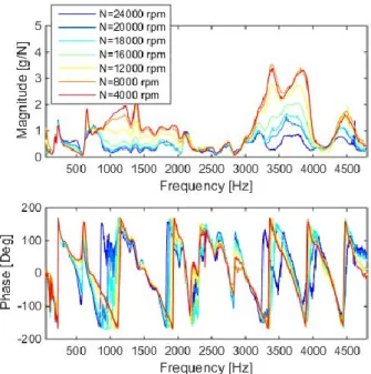
The data from the accelerometer measurements presented in Figure 10 and Figure 11 bring new information especially at higher frequency were signal to noise ratio is very low with the displacement sensors. Between 3000 and 4000Hz at the lower speed, two modes are noticeable on the accelerometer results. The amplitude and the frequency vary with spindle speed suggesting that the related modes are subject to spindle dynamic effects. A similar mode is observed at about 4500Hz on the two figures. The shaft modes observed with the displacement sensors at 650Hz for example are still visible with the accelerometers as well as some machine tool modes below 300Hz.
Figure 10: FRF from accelerometer measurements at front bearing (MFW1709 spindle, X direction)
Figure 11 : FRF from accelerometer measurements at rear bearing (MFW1709 spindle, X direction) Accelerometers are placed on the spindle housing at both the front and rear bearing positions. These locations may help the characterization of the joint between the shaft and the spindle housing. It might also provide helpful data to study the modes shapes as bearing positions are often nodes of certain modes.
Further investigations will be done including a numerical model of the spindle in order to precisely identify the variations of modes and couplings with speed.
6. Conclusion
An experimental investigation of the dynamic behavior of two industrial HSM spindles with different design has been carried out. A specific non-contact excitation device based on two opposite sets electro-magnet has been developed in our lab to perform in rotation FRF measurement with a swept sine excitation. Results have been obtained from the spindles rotating until 24000rpm in both X and Y directions. The obtained responses have been validated with hammer impact tests performed between the same two points. Harmonics removal on signals has been performed with a cepstral domain based method. Besides, it reduced the noise on the spectrum effectively without having to resample the signal in the angular domain. The analysis of the results reveals interesting variations of modes frequency and modes coupling with speed. The comparison between the two industrial spindles showed that design has an influence on the dynamic behavior evolutions with speed. The use of multiple sensors enabled specific observations, like the distinction between machine tool modes and spindle modes. Higher frequency modes could be observed with the use of accelerometer that also brings new information for the study of mode shapes.
Acknowledgements
The research was conducted within the context of the French FUI project “QuaUsi”. The authors would like to thanks the contribution of Precise Fischer France and Europe Technologies France.
References
[1] Altintaş, Y., and Budak, E., 1995, “Analytical Prediction of Stability Lobes in Milling,” CIRP Ann. - Manuf. Technol., 44(1), pp. 357–362. [2] Cao, Y., and Altintas, Y., 2004, “A General
Method for the Modeling of Spindle-Bearing Systems,” J. Mech. Des., 126(6), p. 1089.
[3] Gagnol, V., Bouzgarrou, B. C., Ray, P., and Barra, C., 2007, “Model-based chatter stability prediction for high-speed spindles,” Int. J. Mach. Tools Manuf., 47(7-8), pp. 1176–1186.
[4] Albrecht, A., Park, S. S., Altintas, Y., and Pritschow, G., 2005, “High frequency bandwidth cutting force measurement in milling using capacitance displacement sensors,” Int. J. Mach. Tools Manuf., 45(9), pp. 993–1008.
[5] Schmitz, T. L., Ziegert, J. C., and Stanislaus, C., 2004, “A method for predicting chatter stability for systems with speed-dependent spindle dynamics,” Pap. Present. NAMRC 32 Jun 14 2004, 32, pp. 17–24.
[6] Abele, E., Kreis, M., and Roth, M., 2006, “Electromagnetic Actuator for in Process Non-Contact Identification of Spindle-Tool Frequency Response Functions,” CIRP 2nd International Conference on High Performance Cutting, Vancouver.
[7] Rantatalo, M., Aidanpää, J.-O., Göransson, B., and Norman, P., 2007, “Milling machine spindle analysis using FEM and non-contact spindle excitation and response measurement,” Int. J. Mach. Tools Manuf., 47(7-8), pp. 1034–1045. [8] Matsubara, A., Yamazaki, T., and Ikenaga, S., 2013, “Non-contact measurement of spindle stiffness by using magnetic loading device,” Int. J. Mach. Tools Manuf., 71, pp. 20–25.
[9] Matsubara, A., Sawamura, R., Asano, K., and Muraki, T., 2014, “Non-contact Measurement of Dynamic Stiffness of Rotating Spindle,” CIRP High Performance Cutting (HPC), Elsevier B.V., pp. 484–487.
[10] Tlalolini, D., Rialland, S., Ritou, M., Noel, D., Le Loch, S., and Furet, B., 2013, “Excitateur electromagnétique de broche d ’ usinage,” p. 7.
[11] Randall, R. B., Sawalhi, N., and Coats, M., 2011, “A comparison of methods for separation of deterministic and random signals,” Int. J. Cond. Monit., 1(1), pp. 11–19.
[12] Klein, R., 2013, “Comparison of Methods for Separating Excitation Sources in Rotating Machinery,” Surveillance 7 International Conference, pp. 1–12.
[13] Randall, R. B., Peeters, B., Antoni, J., and Manzato, S., 2012, “New cepstral methods of signal pre-processing for operational modal analysis,” Proceedings of the International Conference on Noise and Vibration Engineering ISMA 2012, pp. 755–764.
[14] Manzato, S., White, J. R., LeBlanc, B., and Peeters, B., 2013, “Development of techniques for enhanced operational modal analysis of wind turbines,” 5th international Operational Modal Analysis Conference.