HAL Id: hal-01717275
https://hal.archives-ouvertes.fr/hal-01717275
Submitted on 13 Dec 2018
HAL is a multi-disciplinary open access
archive for the deposit and dissemination of
sci-entific research documents, whether they are
pub-lished or not. The documents may come from
teaching and research institutions in France or
abroad, or from public or private research centers.
L’archive ouverte pluridisciplinaire HAL, est
destinée au dépôt et à la diffusion de documents
scientifiques de niveau recherche, publiés ou non,
émanant des établissements d’enseignement et de
recherche français ou étrangers, des laboratoires
publics ou privés.
Influence of oxides on friction in hot rolling:
Experimental investigations and tribological modelling
C Vergne, Christine Boher, R Gras, Christophe Levaillant
To cite this version:
C Vergne, Christine Boher, R Gras, Christophe Levaillant. Influence of oxides on friction in hot rolling:
Experimental investigations and tribological modelling. Wear, Elsevier, 2006, 260 (9-10), pp.957-975.
�10.1016/j.wear.2005.06.005�. �hal-01717275�
Influence of oxides on friction in hot rolling: Experimental
investigations and tribological modelling
C. Vergne
a,∗, C. Boher
b,∗∗, R. Gras
c, C. Levaillant
b aAKERS Group, Rue de la Barriere 40, 4100 Seraing, Belgium bCROMEP, Ecole des Mines d’Albi Carmaux, Campus Jarlard, Route de Teillet,81013 Albi CT cedex 09, France
cISMCM- CESTI, 3 Rue Fernand Hainaut, 93407 Saint-Ouen, France
Abstract
In a hot strip mill, the contact established between the hot strip and the work rolls in the first times of running has to be oxide on oxide to allow the strip to be pulled in the roll bite. The oxide scale formed on the roll is submitted to thermo-mechanical stresses and grows up. From a critical thickness, the scale spalls and causes some superficial damage to the rolls and to the strip.
For the roll manufacturers as well as for the steel makers, it is essential to understand the influence of the creation and the growth of such a scale on friction in order to control the antagonist superficial damage and consequently to reduce the running cost of the mill.
The present work aims to study the interaction between the oxides formed on a work roll grade and the coefficient of friction established with a strip steel usually rolled by this roll grade. A high temperature tribometer was set up in a pin-on-disc configuration. A previous part of study showed that friction was dependent on the nature of antagonist materials and the thermal transfer. We observed the establishment of a running-in period in the case of a metal-on-oxide initial contact between the pin and the disc which corresponds to the creation of an oxide layer on the pin.
The mechanisms that allowed the formation of this scale were determined. SEM observations in conjunction with EDS analysis, both inside and outside the contact area on both antagonists, led to the development of a phenomenological model explaining the creation and the movement of oxide debris in the contact.
Keywords: Wear; Friction; Hot rolling; Oxidation; Iron oxide
1. Introduction
The study of the wear behaviour of oxide layers has found a renewed interest with the need to understand their con-tribution to the damage observed in the hot metal forming processes.
∗Corresponding author. Tel.: +32 4 22 97 241; fax: +32 4 22 97 247.
∗∗Corresponding author. Tel.: +33 5 63 49 31 69; fax: +33 5 63 49 30 99.
E-mail addresses:c.vergne@akers.be (C. Vergne), boher@enstimac.fr (C. Boher).
1.1. Hot rolling process
In hot rolling, friction is considered as the “driving force” of the process: “without friction no rolling”[1]. The appear-ance of friction depends mainly on the creation of a sufficient oxide layer at the work roll surface in order to prevent all metal–metal contact or metal–oxide contact between the strip and the work rolls. On the one hand, when a metal–metal con-tact is established, the strip cannot be pulled between the work rolls owing to slipping. On the other hand, when a metal-on-oxide contact is established, friction increases strongly leading to sticking phenomena.
Actually the formation of an oxide layer on the work roll surfaces allows the metal sheet to be driven between the work rolls because of the decrease in the shear forces[2]. In the process, the work rolls are alternately heated by contact with the hot strip and cooled drastically outside the contact by a water spray. In this way, the work rolls are subjected to ther-mal and mechanical stresses which favour the increase of the oxide thickness on the rolls. Above a critical thickness, the upper layer of the oxide scale breaks by thermal and mechan-ical fatigue and spalls under the shearing. The repetition of this damage requires the machining of the roll barrel after a certain running in the mill and contributes to the reduction of the roll lifetime. Moreover, the roll spalling produces the adhesion of oxide debris on the strip surface that leads to the marking of the metal sheet and makes it unusable.
Besides, the coefficient of friction generated between the work rolls and the strip usually tends to decrease with the increase in thickness of the oxide scale on the rolls. This decrease in friction results in a reduction in the rolling force and therefore the torque applied to the rolls, which, in turn, saves energy.
In this way, the creation of an oxide scale on the roll barrel has a direct impact on the operating cost of a hot mill by reducing the damage both on the rolls and on the rolled sheet at the same time as the energy consumption.
Nevertheless the continuous decrease in friction versus the increase in thickness of oxide scale on the work rolls finally may lead to skidding of the strip between the rolls.
1.2. Tribological behaviour of oxides
More generally the tribological behaviour of oxides is ambiguous, being able to be both abrasive and therefore detri-mental or to be lubricant and consequently protective against wear[3–7]. Their ability to be lubricant or abrasive is depen-dent on the fact that the oxides enter into the contact either as free particles or as compacted particles[3]. And the aptitude of the oxides to be either free or compacted into the contact is itself usually correlated on the one hand to the microstruc-tural and mechanical properties of the oxides and on the other hand to the friction conditions – more particularly to the slid-ing speed. In general, the coefficient of friction generated between two oxidised surfaces is considered dependent on the nature, the thickness, the adherence to their substrate and the hardness of the antagonist oxide scales. If the oxide par-ticles are free in the contact and hard, then the predominant mechanism of wear is abrasion and the coefficient of friction is high. If the oxide particles are compacted into the contact until the formation of glazed surfaces, then the predominant mechanism of wear becomes adhesion and the coefficient of friction is low. The sliding speed has a strong influence on the wear mechanisms[8,9]. At high speed, the oxides may reach their melting point and favour an adhesive wear. Low sliding speeds make easy the formation of thicker and wear resistant scales. The tribological behaviour of the iron oxides usually formed on the strip surface were more particularly
empha-sized[10–12]. The rhomboedral hematite !-Fe2O3, which
presents a high hardness at room temperature is known to exhibit an abrasive behaviour and to tend to increase friction and wear. On the contrary, the cubic oxides, the magnetite Fe3O4and the w¨ustite FeO, are more ductile and resist wear
better.
1.3. Tribological behaviour of oxides in hot rolling process
At the industrial level, the wear resistance of work rolls is usually estimated from the amount of hot steel rolled per millimetre of machined roll diameter (t mm−1)[13,14]. This
criterion is too restrictive and does not reveal if the machining of the rolls is decided due to a usual wear or to a rolling incident.
The tribological behaviour of the work rolls can be eval-uated from the evolution of the rolling load in relation to the mill stand[15]. This criterion allows one to define the evolu-tion of fricevolu-tion in the contact. If the rolling load increases, that means friction between the work rolls and the strip increases and vice versa.
The wear mechanisms start to be well known in hot rolling. Whatever the stand in the mill, the predominant wear phe-nomena of the work rolls remain thermal fatigue, abrasion, adhesion and oxidation[13,16,17]. The wear mechanisms in the finishing stands were more particularly emphasised. Thermal fatigue is the result of a mixed effect of the cyclic contact of the roll with the hot strip and the drastic cooling of the roll surface by water spray at the contact exit. This solic-itation repeated at the frequency of the roll rotation induces compressive and tensile stresses in the subsurface of the roll and favours crack nucleation when theses stresses exceed the yield stress. The firecrack pattern may be extended by the oxidation of the roll surface which favours the propagation of cracks in the bulk. In the presence of a carbide network in the roll matrix, the cracks follow the matrix–carbide inter-face. Under shearing, the propagation of the cracks in the bulk may cause the loss and the transfer of roll surface material towards the strip surface[13,18].
As for abrasion, this damage is the result of the cutting effect of the superficial asperities during the relative motion of the antagonist surfaces. Temperature affects wear due to its influence on the development of both the nature and the prop-erties of the contact surfaces[19–21]. This wear mechanism appears as soon as the wear debris present a high hardness and a low ductility even at high temperature and a sharp shape. Some damage like micro-cutting, grooves or plastic defor-mation may occur.
Adhesion usually corresponds to a transfer of the rolled strip (oxide debris) to the roll surface, which contributes to increase the roughness of the rolls and leads to an increase in friction[13].
At last, oxidation is a frequent phenomenon on the roll surface. The formation of oxide scale on the roll is known to exhibit a good friction behaviour. Nevertheless, above a
“critical” thickness, the scale becomes detrimental for the lifetime of the roll and favours some damage like banding on the sheet.
1.4. Aim of the study
However, the interaction of the oxide scale formed on the roll surface with friction and wear is not yet well understood. More generally, the tribological behaviour of the oxides can be analysed through the behaviour of the third body. The third body is usually constituted of oxide debris issued from either the strip or the work rolls and it can be considered as a parameter influencing the development of the friction coefficient.
The formation and the behaviour of the third body remain dependent on the nature, the physical properties and the adherence to the substrate of the oxides. Oxides which are not very adherent to the strip or the rolls could be beneficial against friction[13]as long as they are soft. They enter into the contact area more quickly and therefore contribute to the reduction of the friction coefficient by forming a third body able to accommodate the shear. Other oxides, which adhere strongly to their substrate, irrespective of whether they are soft or hard, contribute to increase shear stresses and fric-tion. In this situation, wear occurs either by abrasion or by oxide spalling.
De facto the tribological behaviour of the oxides is very complex in the hot rolling process because it is influenced by the nature and the physical properties of the oxide scales into the contact. In consequence, the microstructure of the work roll grade and more particularly the carbide content of the matrix are very important[2,13,16–18]. These car-bides reinforce the mechanical resistance and the wear resis-tance of the roll matrix. Nevertheless, they can contribute also to the damage of the work rolls according to two mechanisms:
• on the one hand, they oxidise differently from the matrix and the formed oxides may have a different influence on friction and wear than the rest of the matrix;
• on the other hand, under thermo-mechanical stresses, superficial cracks may occur on the roll and follow the network of primary carbides. In this way, they create some diffusion paths and facilitate internal oxidation of the roll matrix. As mentioned previously, some loops of internal oxidation appear and propagate until they finally emerge at the roll surface. In this way, they con-tribute to produce cohesive wear debris through shearing and they are the cause of significant damage at the roll surface.
For the roll manufacturers as well as for the steel manu-facturers, it is important to understand the contribution the roll grade makes to the damage occurring in the hot rolling process and to determine the interaction between the develop-ment of friction and the oxides taking into account the nature of oxides present in the roll bite. The aim of this study is not to
simulate the hot rolling process but to reproduce a part of the contact mechanics established between a grade of hot work-ing roll and a hot strip material used in the finishwork-ing stands in the first steps of the process. The mechanical contact of a typical rolling bite is decomposed: only the sliding part of the motion is considered, the rolling part of the motion being neglected. The nature of the sliding antagonist surfaces is a thick oxide layer formed on a strip material at a temperature close to the rolling temperature in the finishing stands and a work roll material presenting only a thin oxide layer as a nat-ural passivization product formed at room temperature. The oxide scale considered on the disc is much thicker than the descaled surface of the strip at its entry in the first finishing stands.
Actually the operating conditions of friction tests are rather different from the industrial rolling conditions. Never-theless, the tribological configuration of contact – a sliding motion at a high temperature close to the rolling temperature with an initial hertzian pressure close to the contact pressure in a rolling bite – allows to display the impact of the chemi-cal composition of the work roll grade on friction and wear mechanisms.
Through the tribological tests, this work aims to follow the development of the coefficient of friction along with the cre-ation and the growth of the oxide scale on the roll grade with the increase in temperature of the pin by thermal conduction and radiation by contact with the warm disc. The correlation between wear damage and thermal fatigue damage has not been investigated for instance. Only the influence of oxides and the contribution of alloying elements in the roll matrix on the development of friction are emphasized.
A pin-on-disc tribometer has been developed for high tem-perature use and two kinds of friction tests have been carried out in order to display the influence of the creation of an oxide scale on the pin on the friction evolution. Some interrupted tests have been performed to understand the interaction of the oxides with the running-in period that the friction evolution exhibited. After each tribological test, the SEM observations made on both the pin and disc wear tracks have led to a mod-elling of the evolution of friction coefficient according to the evolution of the oxide debris in the contact.
2. Materials and experimental conditions
2.1. The materials
As part of this study, a tribometer was set up at high tem-perature. In a pin-on-disc configuration, the pin consists of a roll material and the disc consists of a strip steel usually rolled with the roll grade. The chemical composition of used materials is given inTable 1.
2.1.1. The pin
The grade of the pin – a work roll material – is a cast iron strongly alloyed with carbide formers, more particularly
Table 1
Chemical composition of materials (wt.%) Cast iron pin
Cr; 1–2 Mo; 3–5 Nb; 1–2 V; <1
C Si Mn Cr Ni Mo Al Cu
AISI 1018 steel disc 0.18–0.20 0.24–0.29 0.60–0.65 0.12–0.18 0.07–0.13 0.02 0.02–0.06 0.15–0.20
MC carbide formers like Nb and V. The microstucture made of tempered martensite and cementite presents an initial hardness of 63 HRC (or 772 HV) and a roughness Ra of 0.24 ± 0.04 "m.
This grade is an indefinite chill which has been used for 50 years, always currently used in the last stands of mill. The improvement of the new grades is the hardening of the matrix due to an increase of MC carbides content, more particularly through the Nb and V contents[14,17,2,22–24]. The addi-tion of niobium and vanadium in substituaddi-tion of chromium is known to improve the hardness of the matrix and the eutectic carbide and to reduce the fraction and the size of the eutectic carbides[25].
Niobium as well as vanadium precipitate at high tem-perature in the molten alloy before the solidification [26]. Actually, niobium and vanadium carbides are present as a eutectic phase. Niobium unlike vanadium presents a low power of solubility at austenitizing temperature and does not participate in the secondary hardening during tempering. The content and the shape of Nb-carbides is directly linked to the carbon content and the Nb-content.
The Nb-carbide may exhibit a cubic or octaedric shape for a high content and only an eutectic shape for a low con-tent. Vanadium may contribute to the hardening of the matrix either by a solid solution hardening in eutectic carbides for low contents or by direct precipitation of MC carbides above. The addition of niobium and vanadium to the high alloy steels is known to reinforce wear resistance, firecrack resis-tance and hardening at room temperature. But vanadium unlike niobium is known to favour a catastrophic oxidation of alloys.
That’s why more and more tool steels for cold working tools as well as for hot working tools present some con-tents in MC carbide formers like Nb or V even if their thermo-mechanical behaviour is not well known at higher temperature. More particularly, the influence of vanadium and niobium on the tribological behaviour of this kind of steels at high temperature is unknown.
2.1.2. The disc
The grade of the disc – a strip material – is a low carbon steel (AISI 1018 steel), a steel usually rolled by the stud-ied grade of work roll. The microstructure is ferritic-pearlitic with an initial hardness of 168 Hv and a roughness Ra of 0.04 ± 0.02 "m. The oxidation of this steel at high tempera-ture is parabolic and contributes to form a thick scale (around 200 "m after 1 h and 350 "m after 2 h at 950◦C) on the disc
surface.
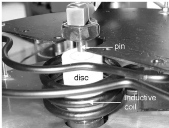
2.2. The tribometer
The principle of the pin-on-disc tribometer is presented on theFig. 1.
The disc is heated by high frequency induction up to a maximum temperature of 1200◦C. Its superficial temperature
is checked either by a K-type thermocouple welded on the surface or by an infra-red pyrometer.
The pin is instrumented with two K-type thermocouples located radially at a depth of 3 mm and respectively at 1.1 mm and 3.4 mm from the contact surface of the pin. The pin temperature increases by thermal conduction, radiation, con-vection and friction. Afterwards the recorded temperatures of the pin are treated by an inverse method[27]to determine the average temperature at the pin surface during the friction tests. The results of this work as a whole will be the purpose of a next paper[27].
During each friction test, a Coulomb-type coefficient of friction is recorded from a strain gauge sensor. This coeffi-cient corresponds to the ratio of macroscopic forces which are the resistant force to the motion and the normal force applied on the pin.
In order to obtain a sufficient pressure of contact with a low normal load, the pin shape presents an hemispherical surface of contact. In this way, for a load ranging from 2.5 to 20 N, the hertzian pressures vary from 130 to 280 MPa at the start of the friction test.
2.3. The tribological tests
The tribological test has been carried out in two steps: • The first one corresponds to the static pre-heating of the
disc – up to 950◦C by a high frequency induction – while
the pin is maintained at room temperature outside the con-tact. When the temperature is reached, the disc is held at high temperature for 1 h. During all the pre-oxidation time, a K-type thermocouple welded outside the wear track records the superficial temperature of the disc. This tem-perature is controlled also by an infra-red pyrometer. • In the second step, after 1 h of disc pre-oxidation, the pin
is brought into contact with the disc, the thermocouple welded at the disc surface is cut and the rotating motion of the disc is immediately started. The heating of the disc is not interrupted between the end of the disc pre-oxidation and the start of sliding.
The operating conditions applied for each kind of test are: • a normal load of 2.5, 10 and 20 N,
• a linear sliding speed of 0.04, 0.1 and 0.3 m s−1.
The test conditions were chosen very soft in order to be able to observe the behaviour of the antagonist oxide scales in the contact zone without destroying them too fast.
For each test condition, three tests have been carried out in order to verify the reproducibility of the results. Only the results with a normal force of 10 N and a linear sliding speed of 0.04 m s−1 are emphasized in the present paper.
Never-theless, the phenomena observed in the present case remain valid for the other test conditions.
3. Tribological results and SEM observations
3.1. A running-in period
In a previous paper[28], the influence of the creation of an oxide scale on the pin surface on the evolution of the coefficient of friction was displayed.
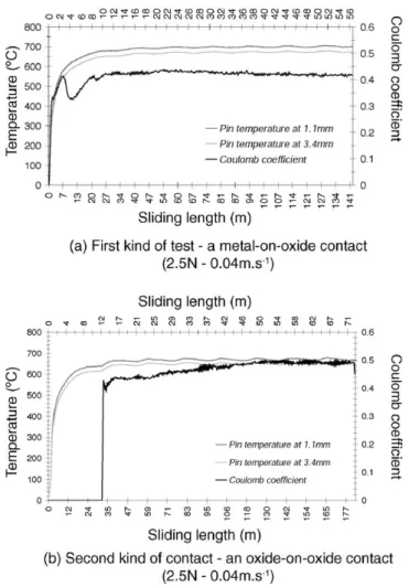
Two kinds of contact were tested. On the one hand, the pin was brought into contact with the pre-oxidised disc and the sliding was started immediately. In this case, the initial contact was considered as a metallic pin on an oxidised disc. On the other hand, the pin was put on the pre-oxidised disc and the stabilization of the temperature in the pin – estab-lished essentially by thermal conduction and radiation from the warm disc – was waited for before starting the sliding. In this case, the initial contact was considered as an oxidised pin on an oxidised disc.
In the first kind of tests – a metal-on-oxide contact – a running-in period was observed in the first 15 min of slid-ing before the stabilization of the friction coefficient. In the second case – an oxide-on-oxide contact – the coefficient of friction reached a stabilized value very quickly and the transi-tory period was considered as insignificant. For both kinds of test, the average value of the friction coefficient, the average value of the temperatures in the pin (Fig. 2) and the superfi-cial features of damage on the antagonist surfaces were found identical in the stabilized period of the coefficient of friction. The running-in period was attributed to the formation of an
Fig. 2. An example of experimental curves of friction and pin temperature versus sliding length.
oxide scale on the pin surface. So the evolution of friction coefficient was estimated dependent on the nature and the thermal transfer initially established between the antagonist surfaces (Fig. 3).
In the present study, we focussed on the tribological tests where the initial contact was a metallic pin on a pre-oxidised disc.
In order to understand the influence of the pin microstruc-ture and more particularly the contribution of its MC carbides (NbC or spinels (Nb, V)C) on the evolution of the coefficient of friction in relation to their nature and their location in the contact zone, some tribological tests were interrupted at dif-ferent intervals during the running-in period and beyond.
A typical tribological test has been subdivided into four steps (Fig. 3):
• the first one, noted Stage 1, corresponds to the start of the friction curve when the coefficient of friction increases; • the second one, noted Stage 2, is the following part of the
curve when the coefficient of friction decreases;
• the third one, noted Stage 3, corresponds to the re-increase in the coefficient of friction after the minimum value;
Fig. 3. The four tribological stages and the three interrupted points consid-ered in a typical friction test.
• and the last one, noted Stage 4, the stabilization step of friction.
The stages from 1 to 3 constitute the running-in period of the friction curve. The interruption of the friction tests were carried out in three steps:
• the first one at the minimum value of the coefficient of friction at the end of the stage 2,
• the second one when the coefficient of friction increases again during the stage 3,
• the last one after 1 h of friction in the stage 4.
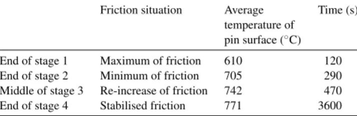
For a better understanding of the tribological phenom-ena, the average values of the superficial temperature of the pin determined by inverse method were reported in the
Table 2according to the different interruption time. The ther-mal model integrates the Beck’s resolution method which compares the calculated temperatures and the experimental values in order to determine the density of thermal flux at the pin contact surface[29].
The times given for each interrupted point of friction tests are representative only in the specific conditions of 10 N and 0.04 m s−1. The length of the running-in period on the friction
curves is not constant versus the test conditions. The stabili-sation length of friction is observed as being an exponential function of the mechanical power. This stabilisation length
Table 2
Pin surface temperature at the different interruption times issued from the thermal modelling (950◦C, 10 N, 0.04 m s−1)
Friction situation Average temperature of pin surface (◦C)
Time (s)
End of stage 1 Maximum of friction 610 120 End of stage 2 Minimum of friction 705 290 Middle of stage 3 Re-increase of friction 742 470 End of stage 4 Stabilised friction 771 3600
Fig. 4. Stabilisation length of friction (length of running-in period) vs. nor-mal load and sliding speed.
increases significantly with the sliding speed and decreases more noticeably with the normal load (Fig. 4).
3.2. SEM observations
The antagonist surfaces – the pin and disc surfaces – were observed by SEM in conjunction with EDS analysis after each friction test. The aim of these observations is to estimate the contribution of the oxide scales to the evolution of the Coulomb coefficient in relation with their nature and their location into the contact.
3.2.1. Observations outside the wear track
In order to identify correctly the wear mechanisms, it is advisable to study the surface morphologies of the pin and the disc away from the wear tracks before examining the wear features.
The tribo-elements involved into the contact zone and thus in the development of friction are observed outside the wear track but very close. The oxidation of the pin surface up to 640◦C for 4 min leads to the following oxide morphologies
(Fig. 5).
The oxide scale formed on the pin is complex owing to the composition and the microstructure of the white cast iron. A dark scale reveals crimps, which seem to follow partly the machining ridges or to develop perpendicularly to these ones (Fig. 5(1)). The background oxide scale as a whole is essentially made up of iron oxide with some traces of Cr, V and Mn. At the pin’s edge far from the wear track, iron oxide needles are observed. According to the literature[30], they could be made of a kind of rhomboedral hematite (!-Fe2O3),
which appears below 400◦C.
Other forms of oxides are observed:
• large excrescences of Fe-Nb oxide (Fig. 5(1) and (2)), • small excrescences of Fe-Nb-V oxide.
These oxides are formed by the oxidation of the MC car-bides – NbC and spinels (Nb,V)C) – present in the pin matrix. For example, the large excrescences rich in Fe-Nb present a
Fig. 5. SEM and EDS analysis of the oxidised pin surface outside wear track.
stcechiometry very close to Fe2NbO4oxide. These NbC
car-bides oxidise above 430◦C.
On the disc, the oxide scale is simpler (Fig. 6). This scale corresponds to an oxidation period of more than 1 h at 950◦C.
It reveals a pitted structure (Fig. 6(1)). At higher magnifi-cation, these pits appear as craters whose width can reach several hundreds of micrometers. The disc surface, made up of plateau and craters, displays a microstructure of columnar cells of iron oxide (Fig. 6(2)).
For the other stages of the friction tests, the morpholo-gies identified above remain unchanged for both pin and disc. They can however be magnified by increasing the pin temper-ature or the holding time in contact. Essentially an increase in oxide thickness is observed.
3.2.2. Observations in the wear track
After each interrupted test, the features of both contact surfaces were investigated.
3.2.2.1. At the maximum value of the coefficient of friction – end of stage 1. This is the only part of the friction–time curve
where no interrupted test has been performed. The physical state of the tribological contact at the end of the stage 1 was extrapolated. At the beginning of the test, the initial contact between the pin and the disc is considered as metal on oxide at high temperature around 950◦C. Before being brought into
contact with the disc, the pin presents superficially a natu-ral passivization scale formed at room temperature whose the thickness is so thin that the pin surface is considered as metallic due the predominant mechanical influence of the bulk material.
When the pin is put on the disc, the surface of the disc creeps under loading and the contact surface of the pin becomes circular. When the motion of the disc is started, the contact surface assumes a quite elliptic shape due to a difference of stresses between the entry and the exit side of the contact and the edges of the contact zone. This elliptic shape of the pin wear track is more marked for the low test conditions and tends to become circular and more compact with the friction time increasing (Fig. 7).
The first increase observed on the friction–time curve cor-responds to the increase in the shearing force necessary to
Fig. 6. SEM and EDS analysis of the oxidised disc surface outside wear track.
break the micro-junctions established at the interface of con-tact between the metallic asperities of the pin and the oxidised asperities of the disc.
3.2.2.2. At the minimum value of coefficient of friction – end of stage 2. During the entire sliding period, the disc is con-tinuously heated by induction at 950◦C. The temperature of
the pin rises continuously by thermal conduction, radiation,
convection and friction until around 684◦C at the
maxi-mum value of friction. The free surface of the pin has oxi-dised continuously, more particularly the MC-carbides like Nb-carbides and (Nb,V)-carbides which start to oxidise at 430◦C.
These oxidised carbides form some excrescences dis-tributed on all the pin surface in particular close to the contact zone.
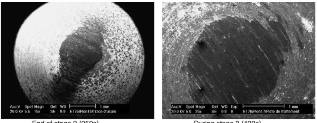
Fig. 7. Pin wear track at the end of the different interrupted tests (10 N, 0.04 m/s).
With sliding, the initial hertzian area increases and the excrescences of oxidised carbides rich in Nb come gradually into the contact. Composed of little grains, the excrescences are subjected to an attrition phenomenon which tends to decrease shear and also friction.
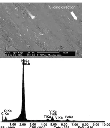
At the minimum of the coefficient of friction (end of stage 2), some little grains of Nb-oxide and some white trails
rich in Nb-oxide are observed in the wear track of the pin (Fig. 8).
On the antagonist surface of the disc, some grains of Nb-oxides are observed as agglomerated at the top of the columnar cells of Fe-oxide (Fig. 9).
This assumption is confirmed by the EDS analysis (Fig. 9) and the observation of some excrescences of oxidised
Fig. 9. SEM and EDS analysis of disc wear track at the minimum value of friction coefficient (end of stage 2).
carbide partially abraded at the edge of the pin wear track (Fig. 10).
Besides, the average length of white trails observed on the pin wear track corresponds to the average distance between the columnar cells of Fe-oxide observed on the disc surface.
The roughness of the oxidised disc surface due to the columnar cells of Fe-oxides causes a cutting of the excres-cences of oxidised Nb-carbides or (Nb, V)-carbides present at the pin surface. In this way, the white grains constituting
the excrescences are transferred from the pin surface to the disc surface.
3.2.2.3. New increase in coefficient of friction – during stage 3. The wear track on the pin becomes gradually more circular and more compact. The contact area presents always some white trails but to a lesser extent. These tracks are always rich in Nb while the remaining part of the wear track is made up of iron oxide with some traces of Cr, V and Ni (Fig. 11(1)).
Fig. 10. SEM observation: excrescences of oxidised Nb-carbides partially abraded at the edge of the pin wear track.
At high magnification, the pin wear track shows some damage resulting from surface fatigue: cracks and scaling arising from adhesion (Fig. 11(2)). In these damaged zones, apart from iron oxide, traces of Nb, V and Si are found.
The break of the sheared oxide scale occurs at the metal–oxide interface in the Si-oxide scale. All the mechan-ical phenomena observed on the pin are responsible for the increased friction.
The contact surface of the disc still reveals the craters formed during its pre-oxidation phase. These craters, made of columnar cells of iron oxide, form some anchorage points for the wear debris generated in the contact. These anchorage zones extend as the friction increases.
The layer of oxide debris seems to be more compact and thicker.
The composition of the agglomerated debris (Fig. 12) is iron oxide in association with traces of Nb, V and Si. The scaling of the pin wear track and the attrition of the scaled chips feed the debris layer.
3.2.2.4. After 1 h of friction – end of stage 4. After 1 h of sliding, the coefficient of friction is completely stabilised and the wear mechanisms do not change a lot and do not produce more debris inside the contact area. The pin wear track once more tends to become more and more circular and seems to be very compact.
At high magnification (Fig. 13), some crack-like damages are observed in the contact area, which result from the shear stresses in the upper oxide layer. The opening of these defects shows that the thickness of the surface affected by friction is rather thin. Inside the cracks, we find again the morphology of the oxide formed on the pin outside the wear track. The chemical composition of the wear track is only iron oxide with no further traces of Nb, V or Si.
Therefore, at the end of test, when the coefficient of fric-tion is stabilised, only iron oxide is involved in the contact interface.
The wear track on the disc is wide after 1 h of sliding. After the separation of the mating tribological system components and during cooling, two phenomena are apparent:
Fig. 11. SEM and EDS analysis of pin wear track when the coefficient of friction increases again (during stage 3).
Fig. 12. SEM and EDS analysis of disc wear track when the coefficient of friction increases again (during stage 3).
• some large cracks formed at the centre of the wear track due to the thermal stresses during the cooling of the sample;
• some small cells observed in the wear track always located at the extreme surface of the columnar cells of iron oxide. These cells correspond to a new or a re-oxidation of the elements constituting the wear track (Fig. 14).
These observations reveal the stress level of the sheared oxide layer on the disc and its behaviour, comparable with that of a ceramics.
4. Wear model
Outside the wear track, the pin constituted by the indef-inite chill presents a quite complex oxidised surface with a background made of iron oxide. Excrescences rich in Nb and Nb-V ensuing from the oxidation of the MC carbides are distributed at the pin surface near the wear track border.
Other morphologies are observed like iron oxide needles supposed to be hematite on the edge of the hemispherical surface of the pin, farther from the pin tip and where the surface temperature is lower.
Fig. 13. SEM and EDS analysis of pin wear track when the coefficient of friction is stabilised (stage 4).
All these structures of oxides emerging from the pin sur-face constitute preferential sites of contact with the oxidised disc surface.
On the oxidised disc in AISI 1018 steel, the morphology of the oxide is simpler. The superficial oxide scale is only made of iron-oxide with small craters distributed at the surface. Its basic structure is constituted of columnar cells of iron oxide.
The microscopic study of wear features after tribological tests showed the evolution of a part of these morphologies under friction.
A scenario was elaborated which explains the influence of these oxide morphologies on the evolution of friction coeffi-cient.
Figs. 15 and 16 present the modelling of each stage of friction evolution.
Fig. 15presents the morphology oxide scales formed on the antagonist surfaces after 1 h of disc pre-oxidation and some minutes of contact of the pin with the warm disc. On the pin, two morphologies are observed. On the one hand, a thin and adherent iron oxide scale probably composed by magnetite with a very thin hematite scale as upper layer cover continuously the pin surface. On the other hand, excrescences
rich in Nb-oxide and issued from oxidation of matrix carbides (NbC or (Nb, V)C carbides) emerge dispersed everywhere on the pin surface. On the disc, four scales are noted. As outer scale, a thin hematite scale identified as !-Fe2O3
rhomboe-dral hematite formed at high temperature (above 400◦C) is
observed. As underlayer, a porous magnetite scale is found with a lot of porosities considered as the result of oxygen diffusion paths and the growth stresses of oxide scales. The inner scale and the thickest one is the wiistite scale in which some aggregates of magnetite formed during cooling of the tribo-system are observable. At the metal–oxide interface, a thin oxide scale rich in silicon is exhibited with a big fracture. The appearance of this fracture has two origins: on the one hand, the stresses generated during cooling of the sample, on the other hand, the presence of Si-oxide which presents a low melting point limiting the adherence of the scale on the disc surface.
For the modelling, only the two first outer iron oxide scales formed on the disc are taken into account while all the oxide scale formed on the pin is considered.
When the pin is put on the disc at 950◦C, its temperature
increases very quickly owing to the important radiation from the disc surface and the thermal conduction by contact.
Fig. 14. SEM and EDS analysis of disc wear track when the coefficient of friction is stabilised (stage 4).
In a few minutes, the pin surface temperature exceeds 500◦C, a temperature from which some carbides start to
oxi-dise. In this way, the cementite oxidises from 458◦C and
the MC carbides type of NbC and VC, respectively, at 430 and 492◦C. These last one are at the origin of the
forma-tion of excrescences on the pin surface around the wear track border.
The excrescences are constituted by agglomerated small grains of oxide with a cauliflower-type macrostructure. Prominent at the pin surface close to the wear track (Fig. 15), these oxidised structures come preferentially into contact with the disc.
Under the action of the applied normal load and the shear, these excrescences are compressed and cut off (Fig. 15).
Formed by agglomerated small grains, the Nb-oxide excrescences are sheared and move in the contact in form of free small grains by attrition. In this way, they contribute to the third body formation.
They are found again in the disc craters which constitute of preferential sites of anchorage in form of agglomerated grains and on the pin, after shearing and rolling, in form of white trails.
The remaining part of wear track is made of iron oxide, abraded and plastically deformed. This phenomenon results from the shearing and loading of the background iron oxide scale formed on the pin as well as on the disc.
It is the first phenomenon of transfer from the pin to the disc which is responsible of the minimum value of friction coefficient (stage 2). The friction attenuation can be explained by a decrease of the tangential force due to attrition and rolling of the Nb-oxide grains in the contact.
These small grains seems in fact to roll in the contact until they anchor at the surface asperities of the disc, and more particularly in the craters observed onFig. 6(1) and (2).
The Nb-oxide grains issued form the oxidation of MC carbides are located in the disc craters and they are going to become preferential sites of contact with the oxidised disc surface.
The iron oxide scale at the pin surface goes on growing during friction and comes in contact with the Nb-oxide grains agglomerated in the disc craters. These grains initiate a new transfer of iron oxide from the pin to the disc.
The tribological contact between the pin and the disc becomes step-by-step iron oxide on iron oxide. The friction
Fig. 15. Modelling of the contact between the pin and the disc at the end of the stage 1 from SEM observations.
generated between both oxidised surfaces causes a strong interaction of these surfaces and their plastic deformation.
The shearing stresses are so high that phenomena of mechanical fatigue and delamination of the oxide scale appear at the pin contact surface.
The sheared oxide scale of the pin is so thin that its scaling appears at the metal–oxide interface in the Si-oxide scale.
This observation explains the Si traces found at the extreme surface of the pin.
These wear mechanisms clarify the increase of the coef-ficient of friction (stage 3).
During sliding, the iron oxide scale of the disc grows continuously due to high temperature being maintained. The thickness of iron oxide is so high than the Nb-oxide grains transferred to the disc surface are trapped in the iron oxide scale.
Henceforth, the two contact surfaces of pin and disc are sheared in their superficial iron oxide scale. Then it becomes very difficult to determine the source of iron oxide observed in the wear tracks.
Both contact surfaces of pin and disc become more compact than in the running-in period and are plastically deformed. Furthermore, the compactness of the sheared iron oxide scale on the pin surface constitutes of a barrier to the oxygen diffusion towards the metal–oxide interface and slows down the oxidation of inner MC carbides.
Only the delaminated zones at the pin surface could allow these carbides to come at the surface and to be oxidised once again.
In this stabilised friction regime (stage 4), the temperature recorded by thermocouples in the pin seems to be stabilised. The tribo-system achieved a thermo-mechanical equilibrium where the wear mechanisms have no more notable influence on the friction coefficient evolution.
These assumptions are confirmed by the SEM obser-vations in the cross sections of both pin and disc (Figs. 17 and 18). The micrographs present the surface of the pin and the surface of the disc on both sides of the wear track limit. In the pin wear track, a thin layer of compacted oxidised debris is observed while in the disc wear track, the consumption of the superficial iron oxide scale identified as hematite is exhibited.
5. Discussion
SEM observations and EDS analysis of wear tracks on both antagonists after each tribological tests have led to the phenomenological modelling of wear mechanisms on both antagonists versus the oxidation level of chemical compo-nents of sliding materials and friction curves.
Whatever the test conditions, a thermal and mechan-ical stability was displayed after a running-in period of friction.
First, this stability was related to the establishment and the holding of a permanent contact between two sliding iron oxide scales formed by either wear transfer or oxidation at high temperature.
Fig. 16. Wear model on oxide influence on friction evolution in the running-in period.
This analysis can be also supported by the approach devel-oped by Felder [1] with the criterion H established in the hot rolling application. The H criterion is defined as the rate between the mean thickness of the oxide scale formed on the strip material and the penetration depth of heat in the oxide scale. The mean thickness of oxide is calculated from the approach of Munther and Lenard [31]and the constant of
oxidation Kpand the activation energy Q determined by
ther-mogravimetric tests. Furthermore, at high temperature, the oxide scale formed on the disc is considered as being mainly wiistite FeO.
This criterion H has been applied at the different stages of the friction curve (Table 3). The H values are always found below 0.05. In this way, the superficial contact area of the
Table 3
Definition of the H criterion in a specific tribological case (950◦C, 10 N, 0.04 m s−1)[1]
Time (s) Mean thickness of oxide scale ("m)a Heat penetration depth ("m) H
End of stage 1 120 243 16.5 × 10³ 0.015
End of stage 2 290 248 24.7 × 10³ 0.010
Middle of stage 3 470 254 31.4 × 10³ 0.008
End of stage 3 720 262 38.9 × 10³ 0.007
End of stage 4 3600 338 86.9 × 10³ 0.004
Characteristics of the thick oxide scale formed on the disc during the friction tests (950◦C, 10 N, 0.04 m s−1). aThickness calculated from constants of oxidation K
Fig. 17. SEM observation: cross-section of the disc at the wear track limit.
disc is considered as cooled by contact with the pin and fric-tion corresponds always to a Coulomb-type fricfric-tion. Shearing is proportional to the normal load and is not very sensitive to the friction duration. The disc oxide scale is harder than
Fig. 18. SEM observation: cross-section of the pin at the wear track limit.
the metal and can be assimilated to a rigid solid. The oxide scale of the disc is not very adherent, brittle and responsi-ble for abrasion phenomena. Shearing remains located at the contact interface. Then no modification of wear mechanisms
and tribological sites of contact is observed. The friction evo-lution is only due to a continuous circulation of iron oxide debris into the contact.
The analysis of contact pressures versus the test conditions shows that the tribological test conditions have a negligible effect on friction and wear mechanisms.
Contact pressures have been compared between the begin-ning and the end of friction tests (Fig. 19). The initial hertzian pressures have been determined versus the surface chemistry considered as predominant against the mechanical behaviour of contact, either as w¨ustite which is the thickest iron oxide scale formed at high temperature on the disc or as the bulk material according to its mechanical properties at high tem-perature.
At the end of tests, the contact pressures have been deter-mined either as apparent contact pressures or real contact pressures. Apparent contact pressures were calculated from
Fig. 20. Determination of apparent and real contact area from imaging analysis.
the measure of the global wear track observed on the pin (Fig. 20). Real contact pressures have been estimated by imaging analysis of the pin wear track in order to determine the real contact area at the extreme surface of pins (Fig. 20). After 1 h of friction, a strong decrease in pressure is observed from 130–400 MPa to 0.6–5.1 MPa according to the test conditions. The difference between the apparent and the real contact pressures is more significant at low test con-ditions. At high test conditions, the real and apparent contact area are very close which indicates that the contact area are compact, typical of iron oxide–iron oxide sliding surfaces, the cission remaining located at the interface. The complete study of the test condition impact on friction and wear mech-anisms is the purpose of an another paper[27].
Besides the running-in period, the contact is stable whatever the test conditions due to a thermal and chemical stabilisation. The influence of the pin chemistry and more particularly the bulk carbides is only significant during the transitory period of the friction curve.
This study suggests all the interest of the judicious choice of the work roll chemistry to adjust the friction value and the wear mechanisms in the rolling bite.
6. Conclusion
The aim of the study was to define the influence of oxi-dation on the friction coefficient in the case of a couple of materials involved in the hot rolling process. The influence of the alloying element oxidation of a cast iron was emphasized more particularly on the friction curve and wear mechanisms. The study was carried through a pin-on-disc tribometer at high temperature. Friction tests stopped in the running-in period of the friction coefficient curve were carried out in order to determine the contribution of oxides formed on the tribo-elements, and more particularly the influence of the oxidised MC carbide rich in Nb and V. The microscopic observations of the wear features of the pin as well as of the disc, led to the development of a wear model explaining the mechanisms of wear debris evolution in the contact, mainly during the running-in period of friction.
This model includes four stages. The first one corresponds to the oxidation of the pin surface by thermal conduction and radiation from the disc, and more particularly the oxidation of the MC carbides rich in Nb and V present in the pin matrix. At the test beginning, a high friction coefficient is recorded due to the shearing forces necessary to break the initial micro-junctions between the passivization oxide scale of the pin considered as metallic and the disc surface oxidised at high temperature during more than 1 h.
The second stage corresponds to the initiation of the third body with the attrition of the oxidised carbides and their trans-fer to the disc surface. In this case, a decrease in friction is observed.
During the entire test, the disc is held at high temperature and its superficial oxide layer goes on growing. Soon the
debris coming from the MC carbide oxidation and transferred to the disc surface are included in the iron oxide scale of the disc, so that the contact becomes step-by-step iron oxide on iron oxide. As a consequence, the friction coefficient starts to rise again. When the contact has totally become iron oxide on iron oxide, a stabilization of friction coefficient is observed corresponding to a chemical and thermal stabilization of the contact.
Actually, the contribution of the alloying elements of the work roll grade is sensible only in the running-in part of the friction curve. Nevertheless, this transitory period constitutes the tribological running phase of hot rolling and the effect of the alloying elements on wear mechanisms and friction was brought out.
It has to be noted, finally, the mutual and beneficial effect of the niobium and the vanadium elements which counter-balances the low chromium content. Above a certain con-tent – usually 2% concon-tent – chromium is known to present at high temperature a good resistance to oxidation and to prevent the selective oxidation of iron. The oxide scale is thin and adherent and provides a good resistance against wear and a low coefficient of friction. Even alloyed alone to chromium[25], vanadium, usually used in cast iron met-allurgy for its contribution to the wear resistance at room temperature, is not enough to obtain such good tribolog-ical properties at high temperature due to its catastrophic oxidation.
Acknowledgement
The authors wish to thank ˚AKERS Group for its contri-bution to this study.
References
[1] E. Felder, Rev. Metal (12) (1984) 931–942.
[2] T.P. Adams, D.B. Collins, 40th MWSP Conference Proceedings, vol. XXXVI, 1998, pp. 427–431.
[3] H.S. Hong, W.O. Winner, Proceeding of the 16th Leeds-Lyon Sym-posium Tribology, Lyon (France) 5–8 September 1989, Elsevier Publishers, 1990, pp. 73–79.
[4] F.H. Stott, J. Glascott, G.C. Wood, Wear 97 (1984) 93–106.
[5] F.H. Stott, J. Glascott, G.C. Wood, Proc. R. Soc. Lond. A402 (1985) 167–186.
[6] J. Jiang, F.H. Stott, M.M. Stack, Wear 181/183 (1995) 20–31. [7] M.B. Peterson, J. Calabreses, S. Li, X. Jiang, J. Mater. Sci. Technol.
10 (1994) 313–320.
[8] F.H. Stott, New Directions in Tribology, Mechanical Engineering Publications, London, 1997, pp. 73–79.
[9] F.H. Stott, Tribol. Int. 31 (l/3) (1998) 61–71.
[10] A. Magnee, C. Gaspard, D. Coutsouradis, Rev. Metal. (1977) 35–52. [11] A. Magnee, C. Gaspard, J. Mignon, L. Habraken, Bull. du Cercle
d’Etudes des M´etaux (1977) 177–241.
[12] A. Magnee, C. Gaspard, M. Gabriel, Metallurgical Reports, CRM No. 57, 1980, pp. 25–39.
[13] S. Spuzic, K.N. Strafford, C. Subramanian, G. Savage, Wear 176 (1994) 261–271.
[14] M. Windhager, 44th MWSP Conference Proceedings, vol. XL, 2002, pp. 1251–1260.
[15] P. Thonus, J.C. Herman, J.P. Breyer, M. Sinnaeve, A. Charlier, D. Liquet, R. Marquet, 38th MWSP Conference Proceedings ISS, vol. XXXIV, 1997, pp. 43–49.
[16] M. Boccalini Jr., A. Sinatora, Proceeedings of the 6th International Tooling Conference, Karlstadt University, Sweden, 10–13 September, 2002, pp. 425–438.
[17] A. Molinari, M. Pellizzari, A. Biggi, G. Corbo, A. Tremea, Proceed-ings of the 6th International Tooling Conference, Karlstadt Univer-sity, Sweden, 10–13 September, 2002, pp. 365–377.
[18] R. Colas, J. Ramirez, I. Sandoval, J.C. Morales, L.A. Leduc, Wear 230 (1999) 56–60.
[19] I. Guillot, Thesis of Universit´e Technologique de Compi´egne, France, 1990.
[20] D.T. Blazevic, 37th MWSP Conference Proceedings, ISS-AIME, vol. 33, 1996, pp. 33–38.
[21] T. Fukagawa, H. Okada, Y. Maehara, ISIJ Int. 34 (1999) 56–60. [22] Y. Matsubara, M. Hasimoto, 44th MWSP Conference Proceedings,
vol. XL, 2002, pp. 1223–1232.
[23] A. Biggi, A. Ippoliti, A. Molinari, 40th MWSP Conference Proceed-ings, vol. XXXVI, 1998, pp. 419–426.
[24] Patent application no. EP 0871 784.
[25] S. Wilmes, G. Zwick, Proceedings of the 6th International Tooling Conference, Karlstadt University, Sweden, 10–13 September, 2002, pp. 227–243.
[26] S. Kheirandish, S. Mirdamadi, Y.H.K. Kharrai, Steel Res. 68 (10) (1997) 457–461.
[27] C. Vergne, PhD Thesis, ENSMP, 2001, 247 pp.
[28] C. Vergne, C. Boher, C. Levaillant, R. Gras, Wear 250 (2001) 322–333.
[29] J.V. Beck, J. Heat Transfer 99 (1977) 314.
[30] J. Benard, L’oxydation des m´etaux, tome I: Processus fondamentaux, Ed. Gauthiers-Villars (1962).
[31] P.A. Munther, J.G. Lenard, J. Mater. Process. Technol. 88 (1999) 105–113.