HAL Id: hal-00473631
https://hal.archives-ouvertes.fr/hal-00473631
Submitted on 25 Jun 2019
HAL is a multi-disciplinary open access
archive for the deposit and dissemination of
sci-entific research documents, whether they are
pub-lished or not. The documents may come from
teaching and research institutions in France or
L’archive ouverte pluridisciplinaire HAL, est
destinée au dépôt et à la diffusion de documents
scientifiques de niveau recherche, publiés ou non,
émanant des établissements d’enseignement et de
recherche français ou étrangers, des laboratoires
On the Dynamic Properties of Rigid-Link Flexible-Joint
Parallel Manipulators in the Presence of Type 2
Singularities
Sébastien Briot, Vigen Arakelian
To cite this version:
Sébastien Briot, Vigen Arakelian. On the Dynamic Properties of Rigid-Link Flexible-Joint Parallel
Manipulators in the Presence of Type 2 Singularities. Journal of Mechanisms and Robotics, American
Society of Mechanical Engineers, 2010. �hal-00473631�
Sébastien Briot
Dpt. de Génie Mécanique et Au-tomatique - L.G.C.G.M. EA3913
Institut National des Sciences Appliquées Rennes, France sbriot@yahoo.fr
Vigen Arakelian
vigen.arakelian@insa-rennes.fr
On the Dynamic Properties
of Rigid-Link Flexible-Joint
Parallel Manipulators in the
Presence of Type 2
Singu-larities
In our previous work [1], the dynamic properties of rigid-link parallel manipulators, in the presence of Type 2 singularities, have been studied. It was shown that any parallel manipulator can pass through the singular positions without perturbation of motion if the wrench applied on the end-effector by the legs and external efforts of the manipulator are orthogonal to the twist along the direction of the uncontrollable motion. This condition was obtained using symbolic approach based on the inverse dynamics and the study of the Lagrangian of a general rigid-link parallel manipulator. It was validated by experi-mental tests carried out on the prototype of a four-degrees-of-freedom parallel manipula-tor. However, it is known that flexibility of the mechanism may not always been ne-glected. Indeed, joint flexibility is the main source contributing to overall manipulator flexibility and it leads to the trajectory distortion. Therefore, in this paper, the condition for passing through a Type 2 singularity of parallel manipulators with flexible joints is studied. The suggested technique is illustrated by the example of a 5R parallel manipula-tor with flexible joints. It is shown that passing through singularity is possible if the twelfth order polynomial trajectory planning is applied. The obtained results are vali-dated by numerical simulations carried out using the ADAMS software.
1. Introduction
Over the past decades, with the large development of parallel manipulators, more attention has been paid to their kinematic, ki-netostatic and dynamic properties, and in particular, to their sin-gularities. Several papers deal with singularity analysis of parallel manipulators [2-14]. Most of them present the analysis of singu-lar configurations from a kinematic point of view [2-8]. Algebrai-cally, a singularity analysis is based on the degeneracy of Jaco-bian matrices of the mechanical structure, or of the system of re-ciprocal screws (wrenches) applied to the platform by the legs. However, it is also known that, when parallel manipulators have Type 2 singularities [2], they lose their stiffness and their quality of motion transmission, and as a result, their payload capability. Therefore, the singularity zones in the workspace of manipulators may be analyzed not only in terms of kinematic criterions, from the theoretically perfect model of manipulators, but also in terms of kinetostatic approaches [9-14].
Moreover, while it is demonstrated using the kinetostatic ap-proach that, when subjected to Type 2 singularities parallel ma-nipulator lock up, it has been shown experimentally that, via op-timal dynamic control of manipulators, it is possible to pass through these singular zones. Thus, it is evident that singular con-figurations should also be examined in terms of dynamic aspects. The further study of singularity in parallel manipulators has revealed an interesting problem that concerns the path planning of parallel manipulators under the presence of singular positions, i.e. the motion feasibility in the neighborhood of singularities. In
this case the dynamic conditions can be considered in the design process. One of the most evident solutions for the stable motion generation in the neighborhood of singularities is to use redun-dant sensors and actuators [15]-[18]. However, it is an expensive solution to the problem because of the additional actuators and the complicated control of the manipulator caused by actuation redundancy. Another approach concerns with motion planning to pass through singularity [19]-[25], i.e. a parallel manipulator may track a path through singular poses if its velocity and acceleration are properly constrained. This is a promising way for the solution of this problem. However, only a few research papers on this ap-proach have addressed the path planning for obtaining a good tracking performance. But they have not adequately addressed the physical interpretation of dynamic aspects.
In our recent work [1], optimal force generation in parallel ma-nipulators for passing through the singular positions has been studied. It was shown that any parallel manipulator can pass through the singular positions without perturbation of motion if the wrench applied on the end-effector by the legs and external efforts of the manipulator are orthogonal to the twist along the di-rection of the uncontrollable motion. This paper was concerned with the study of rigid-link parallel manipulators without any flexibility. However, it should be noted that several factors may bring a loss of rigidity in parallel manipulators (elasticity of links, clearance in joints, etc.). But their contribution can be considera-bly reduced for a properly designed and constrained mechanical system. However, even for the most optimum design of
manipu-lator one main source of flexibility remains and it cannot be eas-ily reduced: it is the flexibility in actuated joints, due to the use of Harmonic Drive® systems.
Therefore, in the present work the dynamic condition for pass-ing through the spass-ingular positions is defined in general for paral-lel manipulators taking into account the elasticity in the actuated joints.
The paper is organized as follows. The next section presents theoretical aspects of the examined problem. As in our previous work, using the Lagrangian formulation, the condition of force distribution is defined, that allows the passing of any parallel ma-nipulator through the Type 2 singular positions. In section 3, the suggested solution is illustrated via 5R planar parallel manipula-tor. In section 4, the conclusions are given.
2. Optimal dynamic conditions for passing
through Type 2 singularity
Let us consider a parallel manipulator of m links, n degrees of freedom and driven by n actuators.
The general Lagrangian dynamic formulation for a manipulator with elasticity in actuated joints can be expressed as [26]:
d d L L q q 0 dt d , (1a) a a L L q q τ dt d , (1b) where,
- L is the Lagrangian of the manipulator; L = T−V, where T is
the kinetic energy and V the potential energy due to gravitational forces, friction and elasticity;
- a T n a a a[q1,q2,...,q ] q and a T n a a a [q1,q2,...,q ] q represent the
vectors of position and velocity of the actuators, respectively;
-qd[q1d,q2d,...,qnd]T and q d [q1d,qd2,...,qdn]T represent the
vectors of position and velocity of controlled links, respectively, i.e. the position and velocity of the links that are controlled by the displacement of the actuators in which there are elasticity;
- is the vector of the actuators efforts.
However, for a parallel mechanism, the position (velocity, resp.) of the end-effector is a non-trivial function of the position (velocity, resp.) of the controlled links, therefore it is preferable to rewrite Eq. (1) using the Lagrange multipliers, as follows:
λ B W 0 b T , d d L L q q Wb dt d (2a) a a L L q q τ dt d , (2b)
where is the Lagrange multipliers vector, which is related to the wrench applied on the platform by:
p W AT , x v Wp L L dt d (3) where,
- A and B are two matrices relating the vectors v and q ac-cording toAvBqd. They can be found by differentiating the closure equations with respect to time;
- x[x,y,z,,,]T and [x,y,z,,,]T v are trajectory
parameters and their derivatives, respectively; x, y, z represent the position of the controlled point and and the rotation of the platform about three axes a aand a;
- Wp is the wrench applied on the platform by the legs and ex-ternal forces [27] expressed along axes a aand a.
Expressing Wp in the base frame, one can obtain:
p R b J W W 0 T 0 , (4a) a a L L q q τ dt d , (4b)
where J
R0A1B is the Jacobian matrix between twist t of theplatform (expressed in the base frame) and q , d R0AAD is the expression of matrix A in the base frame, where D is a
trans-formation matrix, of which expression is given in [28].
For any prescribed trajectory x(t), the values of vectors q , d d
q and qd can be found using the inverse kinematics. Thus,
tak-ing into account that the manipulator is not in a Type 1 stak-ingular- singular-ity [2], the terms Wb and R0Wp can be computed. However, for
a trajectory passing through a Type 2 singularity, the determinant of matrix J is indefinite. Numerically, the values of the efforts
applied by the actuators become infinite. In practice, the manipu-lator either is locked in such a position of the end-effector or it can not follow the prescribed trajectory.
It is known that a Type 2 singularity appears when the deter-minant of matrix R0A vanishes, in other words, when at least
two of its columns are linearly dependant [28]. So, one may ob-tain such a relationship:
6 1 j j jA 0 , (5)where Aj represents the j-th column of matrix R0A and j are
coefficients, which in general can be functions of d p
q (p = 1, …,
n). It should be noted that the vector ts = 2, …, 6]T repre-sents the direction of the uncontrollable motion of the platform in a Type 2 singularity.
By substituting (5) into (3), we obtain j
T jλW
A , j = 1, …, 6 (6)
where Wj is the j-th row of vector R0Wp.
Then, from (5) and (6) the following conditions are derived:
6 1 6 1 0 j j j j T j j W A λ . (7)The right term of Eq. (7) corresponds to the scalar product of vectors ts and R0Wp.
Thus, in the presence of a Type 2 singularity, it is possible to satisfy conditions (7) if the wrench applied on the platform by the legs and external efforts R0Wp are orthogonal to the
di-rection of the uncontrollable motion ts. Otherwise, the dynamic model is not consistent. Obviously, in the presence of a Type 2 singularity, the displacement of the end-effector of the manipula-tor has to be planned to satisfy (7). Therefore, our task will be to
achieve a trajectory which will allow the manipulator to pass trough the Type 2 singularities, i.e. which will allow the manipu-lator respecting condition (7).
In the dynamic model of the rigid-link flexible-joint manipula-tor [26], the efforts applied on the actuamanipula-tors may be expressed as follows: ) ( ) , ( ) ( dt d d d d d d d d d L L q D q q q C q q M q q τ , (8)
This equation only depends on the acceleration, velocity and position of the actuators of the manipulator. Therefore, in order to avoid some discontinuity on the efforts , the polynomial used for the trajectory planning should be at least of degree 5 (because ini-tial and final positions are known, and the velocities and accelera-tions at the beginning and the end of the trajectory should be equal to 0). In our previous work [1], it was shown that the condi-tion for passing through the Type 2 singular configuracondi-tions added 3 supplementary conditions, and therefore the polynomial used for the trajectory planning should be at least of degree 8 (the posi-tion, the velocity and the acceleration when passing through the singularity should be constrained).
In the present study, it will be shown that the degree of the polynomial law should be different, when taking into account the flexibility on the actuating system. Indeed, it will be presented further that the efforts applied on the actuators depend as previ-ously on the position, the velocity and the acceleration of the ac-tuators, but also on the jerk and its first derivative. So, due to the addition of elasticity in the actuated joints, the polynomial used for the trajectory planning should be at least of degree 12.
In the next section, an example illustrates the obtained results discussed above. This example presents a planar 5R parallel ma-nipulator, which allows obtaining relatively simple symbolic model for demonstrating the expected results by numerical simu-lations. The results are validated using the ADAMS software.
3. Illustrative example
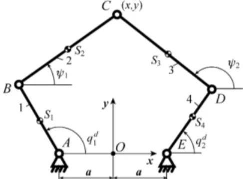
In the planar 5R parallel manipulator, as shown in Fig. 1, the output point is connected to the base by two legs, each of which consists of three revolute joints and two links. In each of the two legs, the revolute joint connected to the base is actuated. Thus, such a manipulator is able to position its output point in a plane.
Fig. 1. Kinematic chain of the planar 5R parallel manipulator. As shown in Fig. 1, the input joints are denoted as A and E with input parameters qd
1 and q2d. The common joint of the two legs is denoted as C, which is also the output point with
con-trolled parameters x and y. A fixed global reference system xOy is located at the center of AE with the y-axis normal to AE and the x-axis directed along AE. The lengths of the links AB, BC, CD,
DE are respectively denoted as L1, L2, L3 and L4. The positions of the centers of masses Si of links from joint centers A, B, D and E
are respectively denoted by dimensionless lengths r1, r2, r3 and r4, i.e. AS1r1L1, BS2r2L2, DS3r3L3 and ES4r4L4.
Actuators 1 and 2 are connected to links 1 and 4, respectively, via harmonic drive systems which are presented by a model simi-lar to that given in [26]. The position of actuator i is denoted as
a i
q
. It is assumed that the actuator i is capable to deliver a cou-ple i to the motor shaft, which is elastically coupled to the link jof the robot (i = 1 or 2, j = 1 or 4). The flexibility is modeled by a torsion spring with stiffness ki. The gear ratio is denoted ni. In the
following of this paper, n1 = n2 = n and k1 = k2 = k. I is the axial ia
moment of inertia of the motor i plus the Harmonic drive system. The singularity analysis of this manipulator [29] shows that the Type 2 singularities appear when legs 2 and 3 are parallel (see also Fig. 2 in [1]).
In both cases, the gained degree of freedom is an infinitesimal translation perpendicular to the legs 2 and 3. However, if L2 = L3, the gained degree of freedom may become a finite rotary motion.
In order to simplify the analytic expressions, we consider that the gravity effects are along the z-axis and consequently the input torques are only due to inertia effects. We also admit that there is no friction in the system. To simplify the computation, it is also preferable to replace the masses of moving links by concentrated masses [30, 31]. For a link i with mass mi and its axial moment of
inertia Ii, we have: i i i i i i i i i i i I m m m m L r L r r r 0 ) 1 ( 0 1 0 1 1 1 3 2 1 2 2 2 2 , (i = 1, 2, 3, 4) (9) where mij (j = 1, 2, 3) are the values of the three point masses
placed at the centers of the revolute joints and at the center of masses of the link i.
In this case, the potential energy V can be written as:
n
n
k V d a/ T d a/ 2 q q q q , (10) where
d d
T d q1,q2 q ,
a a
T a q1,q2q , and the kinetic energy T
as: a T a a D D C C B B S S S S S S S S I m m m m m m m T q q V V V V V V V 2 1 ) ( 2 1 2 2 2 2 4 4 2 3 3 2 2 2 2 1 1 (11) where, mS1m12, mS2 m22, mS3m32, mS4m42, 21 13 m m mB , mCm23m21, mDm33m41. The terms mij
(i = 1, 2, 3, 4) are deduced from the relation (9), VSi is the vector
of the linear velocities of the center of masses Si; VB, VC and VD
are the vectors of the linear velocities of the corresponding axes. Thus the dynamic model can be obtained from (2):
p b J W W 0 T R 5 (12a)
n
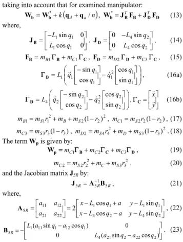
n k Iaqa qd qa/ (12b)taking into account that for examined manipulator:
n
k d a/ * q q W Wb b , Wb*JBTFBJTDFD (13) where, 0 cos 0 sin 1 1 1 1 q L q L B J , 2 4 2 4 cos 0 sin 0 q L q L D J , (14) C B B F mB1 mC1 , FD mD2DmC3C, (15) 1 1 2 1 1 1 1 1 sin cos cos sin q q q q q q L B , (16a) 2 2 2 2 2 2 2 4 sin cos cos sin q q q q q q L D , y x C (16b) 2 2 2 2 1 1 1 m r m m (1 r) mB S B S , mC1mS2r2(1r2), (17) ) 1 ( 3 3 3 3 m r r mC S , 2 3 3 2 4 4 2 m r m m (1 r) mD S D S . (18)The term Wp is given by:
D C B p W mC1 mC2 mC3 , (19) 2 3 3 2 2 2 2 m r m m r mC S C S . (20)
and the Jacobian matrix J5R by: R R R 51 5 5 A B J , (21) where, 2 4 2 4 1 1 1 1 22 21 12 11 5 cos sin sin cos 2 q L y a q L x q L y a q L x a a a a R A , (22) ) cos sin ( 0 0 ) cos sin ( 2 22 2 21 4 1 12 1 11 1 5 L a q a q q a q a L R B . (23)
For a given trajectory qd, the vector of the positions of the
ac-tuators qa can be deduced from (12a), as well as the acceleration
of the actuators q : a
TR
d a k n n q W J W q b* 5 p (24a)
TR
d a n dt d k n q W J W q 2 b* 5 p 2 (24b) Introduction Eq. (24) into Eq. (12b), one can deduce the vector of actuator torques :
Wb JTRWp
qd
Wb JTRWp
a n n dt d k n I 2 * 5 * 5 2 1 .(25)Analyzing this expression, it could be observed that, as terms *
b
W and W depend on the position, velocity and acceleration of p
the input links, the input torques depend not only on these pa-rameters, but also on the jerk and its first derivative. Therefore, on the contrary of rigid manipulators for which, in order to avoid discontinuities in the input torques, a fifth-degree polynomial is sufficient as a control law when the end-effector is not in singular configuration, for non rigid robots, the degree of the polynomial should be increased (indeed, it should be at least a ninth-degree polynomial).
In order to avoid infinite values of the input torques when crossing a Type 2 singularity, Eq. (7) has to be satisfied. From matrix A5R, one can find that the twist of the infinitesimal
dis-placement in the singularity can be written under the form:
T ] cos , sin [ 1 1 s t (26)
Thus, the examined manipulator can pass through the given singular positions if the wrench Wp determined by (19) is
or-thogonal to the direction of the uncontrollable motion ts described by (26).
Let us now consider the motion planning, which makes it pos-sible to satisfy this condition. For this purpose the following pa-rameters of manipulator’s links are specified: L1 = L2 = L3 = L4 = 0.25 m; r1 = r2 = r3 = r4 = 0.5; a = 0.2 m; m1 = m4 = 2.81 kg; I1 =
I4 = 0.02 kg.m2; m2 = m3 = 1.41 kg; I2 = I3 = 0.01 kg.m2; Ia =
0.067 kg/m2; k = 250 Nm/rad; n = 50.
With regard to the prescribed trajectory generation, the point C should reproduce a motion along a straight line between the ini-tial position C0 (x0, y0) = C0 (0.1, 0.345) and the final point Cf (xf,
yf) = Cf (-0.1, 0.145) in tf = 2 s (Fig. 2).
Fig. 2. Initial, singular and final positions of the planar 5R paral-lel manipulator.
Thus, the given trajectory can be expressed as follows: ) ( ) ( ) ( ) ( ) ( ) ( 0 0 0 0 y y t s y x x t s x t y t x f f x (27)
However, the manipulator will pass by a Type 2 singular posi-tion at point Cs (xs, ys) = Cs (0, 0.245) (Fig. 2).
Developing the condition for passing through the singular po-sition (7) for the planar 5R parallel manipulator at point Cs, we
obtain: 0 6 3 ) 48 248 ( 2 2 2 1 1L x y m y mC C (28)
Then, taking into account that the velocity and the acceleration of the end-effector in initial and final positions are equal to zero, the following thirteen boundary conditions are found:
s (t0) = 0, (29) s (tf) = 1, (30) s (ts = 1 s) = 0.5, (31) 0 ) (t0 s , (32) 0 ) (tf s , (33) 1 ) /( ) /( ) (t y y y0 x x x0 s s s f s f , (34) 0 ) (t0 s0 s , (35) 0 ) (tf sf s , (36) ) 6 ) ( 3 /( ) 48 248 ( ) (ts ss mC1L1 xs2 ys2 yf y0 mC2 s , (37) 0 ) (t0 s0 s , (38) 0 ) (tf sf s , (39) 0 ) ( (4) 0 0 s t s dt d , (40) 0 ) ( (4) f f s t s dt d . (41)
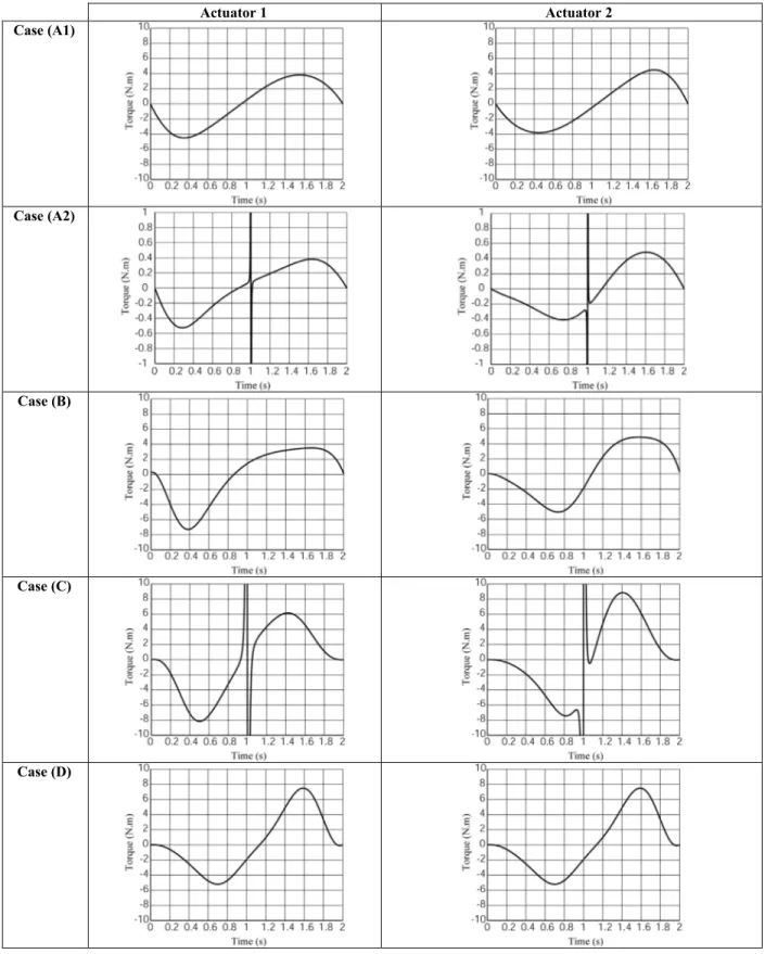
Table 1. Variation of the input torques as a function of the polynomial law used for the trajectory. Actuator 1 Actuator 2 Case (A1) Case (A2) Case (B) Case (C) Case (D)
From (28)-(41), the following twelfth order polynomial trajec-tory planning is found:
12 11 10 9 8 7 6 5 13 . 0 28 . 1 15 . 5 77 . 9 41 . 6 80 . 6 22 . 14 28 . 7 t t t t t t t t t s (42) Thus the generation of the motion by the obtained twelfth or-der polynomial makes it possible to pass through the singularity without perturbation and the input torques remain in the limits of finite values.In order to compare the different cases of trajectory planning, in table 1 are given the values of the input torques obtained using the software ADAMS for the following numerical simulations:
A1: a trajectory between points C0 and C’f (x’f, y’f) = C’f
(-0.1, 0.345) (Fig. 2) without meeting any singularity. For such a case, the following fifth order polynomial law is used s
t 1.25t30.9375t40.1875t5 for the trajec-tory planning out of the singular zone of the rigid-link manipulator without taking into account the flexibility in the actuated joints. In this case the values of the input torques are finite.A2: the fifth order polynomial law
t 1.25t3 0.9375t4 0.1875t5s for the trajectory
planning between C0 and Cf inside the singular zone for
the rigid-link manipulator without taking into account the flexibility in the actuated joints. In this case the val-ues of the input torqval-ues close to the singular positions tend to infinity.
B: the eight order polynomial law s(t) = –0.25851 t3 + 3.84228 t4 – 5.72792 t5 + 3.58909 t6 – 1.07101 t7 + 0.12606 t8 for the trajectory planning of the rigid-link manipulator without flexibility in the actuated joints in-side the singular zone. The obtained results show that the values of the input torques are finite.
C: the ninth order polynomial law
t 3.94t5 6.56t6 4.22t7 1.23t8 0.14t9s for
the trajectory planning of the rigid-link flexible-joint manipulator inside the singular zone. The numerical simulation shows that the values of the input torques close to the singular positions tend to infinity.
D: the twelfth order polynomial law (42) for the trajectory planning of the rigid-link flexible-joint manipulator in-side of the singular zone. The values of the input torques are finite and there are no discontinuities. Thus, the numerical simulations show that the obtained optimal dynamic conditions assume the passing of the rigid-link flexible-joint manipulator through the singular position.
4. Conclusion
At a singular configuration, in the case of an arbitrary genera-tion of forces, a manipulator may not reproduce stable mogenera-tion with prescribed trajectory. Nevertheless it is approved that there are several motion planning techniques, which allow passing through these singular zones. These approaches are simulated by numerical examples and illustrated on several parallel structures. However, in these studies much more attention was focused only on control aspects of this problem and little attention has been paid to the dynamic interpretation, which is a crucial factor for
governing the behavior of parallel manipulators at the singular zones.
In our previous work [1], the dynamic properties of parallel manipulators in the presence of Type 2 singularity have been studied. It was shown that any parallel manipulator can pass through the singular positions without perturbation of motion if the wrench applied on the end-effector by the legs and external efforts of the manipulator are orthogonal to the twist along the di-rection of the uncontrollable motion. This condition was applied to the rigid-link manipulators without clearance or flexibility in the joints. The obtained results showed that the planning of mo-tion for assuming the optimal force generamo-tion can be carried out by a eight order polynomial law.
In the present paper the rigid-link flexible-joint manipulators have been studied. It was shown that the degree of the polynomial law should be different, when the flexibility of actuated joints is introduced into conditions of the optimal force generation in the presence of singularity. The obtained results disclosed that the planning of motion for assuming the optimal force generation in the rigid-link flexible-joint manipulators must be carried out by a twelfth order polynomial law. The suggested technique was illus-trated by an example, which presents 5R planar parallel manipu-lator with flexible joints. The numerical simulations carried out using the software ADAMS validated the obtained theoretical re-sults.
5. References
[1] Briot, S., and Arakelian, V., 2008, “Optimal Force Genera-tion in Parallel Manipulators for Passing through the Singu-lar Positions,” International Journal of Robotics Research, Vol. 27, No. 8, pp.967-983.
[2] Gosselin, C.M., Angeles, J., 1990, “Singularity Analysis of Closed-Loop Kinematic Chains,” IEEE Transactions on
Ro-botics and Automatics, Vol.6, No.3, pp.281-290.
[3] Zlatanov, D., Fenton, R.G., Benhabib, B., 1994, “Singularity Analysis of Mechanisms and Robots via a Velocity-Equation Model of the Instantaneous Kinematics,”
Proceed-ings of the 1994 IEEE International Conference on Robotics and Automation, Vol. 2, pp.980-991.
[4] Zlatanov, D., Bonev, I.A., Gosselin, C. M., 2002, “Con-straint Singularities of Parallel Mechanisms,” IEEE
Interna-tional Conference on Robotics and Automation (ICRA 2002), Washington, D.C., USA, May 11-15.
[5] Hunt, K.H., 1987, “Special Configurations of Robot-Arms via Screw Theory,” Robotica, Vol. 5, pp. 17-22.
[6] Merlet, J.-P., 1989, “Singular Configurations of Parallel Manipulators and Grassmann Geometry,” The International
Journal of Robotics Research, Vol. 8, No. 5, pp.45-56.
[7] Bonev, I.A., Zlatanov, D., Gosselin, C.M., 2003, “Singular-ity Analysis of 3-DOF Planar Parallel Mechanisms via Screw Theory,” ASME Journal of Mechanical Design, Vol. 125, No. 3, pp.573–581.
[8] Briot, S. and Arakelian, V., 2007, “Singularity Analysis of PAMINSA Manipulator.” The 12th World Congress in
Mechanism and Machine Science, 18-21 June 2007,
Besan-çon, France.
[9] Gosselin, C.M., 1992, “The Optimum Design of Robotic Manipulators using Dexterity Indices,” Robotics and
[10] Merlet, J.-P., 2006, “Jacobian, Manipulability, Condition Number, and Accuracy of Parallel Robots,” ASME Journal
of Mechanical Design, Vol. 128, No. 1, pp.199–206.
[11] Angeles, J., 2007, “Fundamentals of Robotic Mechanical Systems: Theory, Methods, and Algorithms,” 3rd edition, Springer, New York.
[12] Alba-Gomez, O., Wenger, P., and Pamanes, A., 2005, Sep-tember 24-28, “Consistent Kinetostatic Indices for Planar 3-DOF Parallel Manipulators, Application to the Optimal Ki-nematic Inversion,” Proc. ASME 2005 IDETC/CIE
Confer-ence, Long Beach, California.
[13] Arakelian, V., Briot, S., and Glazunov, V., 2008, “Increase of Singularity-Free Zones in the Workspace of Parallel Ma-nipulators using Mechanisms of Variable Structure,”
Mechanism and Machine Theory, Vol. 43, No. 9, pp.
1129-1140.
[14] Hubert, J and Merlet, J.-P., 2008, “Singularity Analysis through Static Analysis,” Advances in Robot Kinematics, Springer, pp.13-20.
[15] Alvan, K., and Slousch, A., 2003, “On the Control of the Spatial Parallel Manipulators with Several Degrees of Free-dom,” Mechanism and Machine Theory, Saint-Petersburg, No. 1, pp. 63-69.
[16] Dasgupta, B., and Mruthyunjaya, T., 1998, “Force Redun-dancy in Parallel Manipulators: Theoretical and Practical Is-sues,” Mechanism and Machine Theory, Vol. 33, No. 6, pp.724-742.
[17] Glazunov, V., Kraynev, A., Bykov, R., Rashoyan, G., and Novikova, N., 2004, “Parallel Manipulator Control While Intersecting Singular Zones,” Proc. 15th Symposium on
Theory and Practice of Robots and Manipulators (Ro-ManSy) CISM-IFToMM, Montreal.
[18] Kotlarski, J., Do Thanh, T., Abdellatif., H., and Heimann, B., 2008 “Singularity Avoidance of a Kinematically Redun-dant Parallel Robot by a Constrained Optimization of the Actuation Forces,” In the Proceedings of the Seventeenth
CISM-IFToMM Symposium RoManSy, pp.435-442.
[19] Bhattacharya, S., Hatwal, H., and Ghosh, A., 1998, “Com-parison of an Exact and Approximate Method of Singularity Avoidance in Platform Type Parallel Manipulators,”
Mechanism and Machine Theory, Vol. 33, No. 7, pp.
965-974.
[20] Dasgupta, B., and Mruthyunjaya, T., 1998, “Singularity-Free Path Planning for the Steward Platform Manipulator,”
Mechanism and Machine Theory, Vol. 33, No. 6, pp.
715-725.
[21] Hesselbach, J., Wrege, J., Raatz A., and Becker, O., 2004, “Aspects on the design of high precision parallel robots,”
Assembly Automation, Vol. 24, No. 1, pp. 49-57.
[22] Kemal Ider, S., 2005, “Inverse Dynamics of Parallel Ma-nipulators in the Presence of Drive Singularities,”
Mecha-nism and Machine Theory, Vol. 40, pp. 33-44.
[23] Kevin Jui, C.K., and Sun, Q., 2005, “Path Tracking of Paral-lel Manipulators in the Presence of Force Singularity,”
Transactions of the ASME. Journal of Dynamic Systems, Measurement and Control, Vol. 127, pp. 550-563.
[24] Nenchev, D.N., Bhattacharya, S., and Uchiyama, M., 1997, “Dynamic analysis of parallel manipulators under the singu-larity-consistent parameterization,” Robotica, Vol. 15, No. 4, pp. 375-384.
[25] Perng, M.H., and Hsiao, L., 1999, “Inverse Kinematic Solu-tions for a Fully Parallel Robot with Singularity Robust-ness,” The International Journal of Robotics Research, Vol. 18, No. 6, pp. 575-583.
[26] Spong, M.W., Khorasani, K., and Kokotovic, P.V., 1987, “An Integral Manifold Approach to the Feedback Control of Flexible Joint Robots,” IEEE Journal of Robotics and
Auto-mation, Vol. 3, No. 4, pp. 291–300.
[27] Khalil, W., and Guégan, S., 2002, May 11-15, “A Novel So-lution for the Dynamic Modeling of Gough-Stewart Manipu-lators,” Proc. IEEE International Conference on Robotics
and Automation, Washington DC., USA.
[28] Merlet, J.-P., 2006, “Parallel Robots,” Springer, 2nd edition. [29] Liu, X.-J., Wang, J., and Pritschow, G., 2006, “Kinematics,
Singularity and Workspace of Planar 5R Symmetrical Paral-lel Mechanism,” Mechanism and Machine Theory, Vol. 41, No. 2, pp. 119–144.
[30] Seyferth, W., 1974, “Massenersatz duch Punktmassen in Räumlichen Getrieben,” Mechanism and Machine Theory, Vol. 9, pp. 49-59.
[31] Wu, Y., and Gosselin, C.M., 2007, “On the Dynamic Bal-ancing of Multi-DOF Parallel Mechanisms with Multiple Legs,” Transaction of the ASME. Journal of Mechanical