HAL Id: hal-02325320
https://hal.archives-ouvertes.fr/hal-02325320
Submitted on 22 Oct 2019
HAL is a multi-disciplinary open access
archive for the deposit and dissemination of
sci-entific research documents, whether they are
pub-lished or not. The documents may come from
teaching and research institutions in France or
abroad, or from public or private research centers.
L’archive ouverte pluridisciplinaire HAL, est
destinée au dépôt et à la diffusion de documents
scientifiques de niveau recherche, publiés ou non,
émanant des établissements d’enseignement et de
recherche français ou étrangers, des laboratoires
publics ou privés.
First experimental ambient backscatter communication
using a compact reconfigurable tag antenna
Yvan Kokar, D.-T Phan-Huy, R Fara, K. Rachedi, A. Ourir, J. de Rosny, M
Renzo, Jean-Christophe Prévotet, M. Helard
To cite this version:
Yvan Kokar, D.-T Phan-Huy, R Fara, K. Rachedi, A. Ourir, et al.. First experimental ambient
backscatter communication using a compact reconfigurable tag antenna. 2019 IEEE Globecom
Work-shops (GC Wkshps), Dec 2019, Waikoloa, United States. �10.1109/GCWkshps45667.2019.9024698�.
�hal-02325320�
First experimental ambient backscatter
communication using a compact reconfigurable tag
antenna
Y. Kokar
1, D.-T. Phan-Huy
2, R. Fara
2, K. Rachedi
3, A. Ourir
3,
J. de Rosny
3, M. Di Renzo
4, J.-C. Pr´evotet
1, M. H´elard
11 Univ. Rennes, INSA Rennes, IETR, CNRS, UMR 6164, Rennes, France 2 Orange Labs, Chˆatillon, France
3 ESPCI Paris, PSL University, CNRS, Institut Langevin, Sorbonne Universit´e, Paris, France 4 Laboratory of Signals and Systems, CNRS, University of Paris-Sud XI, Gif-sur-Yvette, France
Abstract—Ambient backscatter communications have emerged as a promising technology for a sustainable development of the Internet of Things (IoT). In such system, a radio frequency (RF) tag can transmit data to a receiver without battery and without generating any new RF wave, just by backscattering the incident RF wave originated by an ambient RF source. The simplest tag is a dipole that is either in an absorbing mode or in reflecting mode to send ”0” or ”1”, and thus leads to a modulation order of 2. Previous solutions to reach higher modulation order, so as to achieve higher data rate, are based on antenna arrays. However, such solutions are not suitable for connected objects, due to their sizes. In this paper, for the first time, we propose a new tag that uses a compact antenna with reconfigurable radiation patterns to provide a high modulation order. We present experimental bit error rate measurements obtained with an experimental test-bed and two tag antennas, both providing 4 states and thus being able to convey 2 bits per symbol. These measurements show that the performance improves with increasing number of receive antennas, and lead to the conclusion that a tag antenna with low cross-correlations between reconfigurable radiation patterns is suitable for backscattering applications in IoT.
Index Terms—Ambient backscatter, Internet of Things, bit error rate, reconfigurable antennas, software-defined radio, green communications.
I. INTRODUCTION
The growing number of devices and objects that wireless network operators have to connect leads to an increase in global energy consumption. Indeed, even though each new generation of mobile network is better in terms of energy and spectral efficiency than the previous one, the power con-sumption and the emission of radio waves continue to increase [1]. In [1], the concept of ”energy-free communicating” (EFC) tags that can communicate with smartphones or the wireless network access points, without battery and without generating any new radio waves, is introduced as a candidate solution for a sustainable development of the internet-of-thing (IoT). The EFC tag harvests energy from ambient sources (such as sun-light, motion and heat) to power its circuit and backscatters radio frequency (RF) waves from ambient source such as Wi-Fi access points, mobile devices or network base stations, for instance. Such EFC tags exploit the ”ambient backscatter”
Receiver
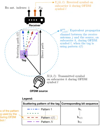
OFDM source Tag
X(k, l): Transmitted symbol on subcarrier k during OFDM symbol l
Hj,i(l)eq : Equivalent propagation channel between the receive antenna j and the source, on subcarrier k, during OFDM symbol l, when the tag is using pattern i(l) Yj(k, l): Received symbol on 1 j NR Rx ant. indexes: S cat te ri n g p at h i( l) D ir ec t p at h
Scattering pattern of the tag Corresponding bit sequence
Pattern 1 Patterni(l) PatternN b1 bi(l) bN Index of the pattern
being used by the tag during OFDM symbol l
Legend:
subcarrier k during OFDM symbol l
Fig. 1: Proposed system model
concept that was first introduced in 2013, by the University of Washington [2] with TV towers as sources, and then studied for various systems [3]. The tag does not generate any RF wave, it backscatters the incident RF wave coming from the source. The most basic tag consists of a dipole antenna (two metallic lines) designed to resonate at the carrier frequency of the source, that is either set in short circuit or open circuit, to send ”0” or ”1” [2]. In one state, the dipole is ”reflecting” or backscattering waves, whereas in the other state it is ”transparent” to RF waves. The receiver detects two different levels of received RF waves and deduces the message sent by
the tag. Such a system is capable of transmitting 1 bit per symbol and then leads to a modulation order of 2.
To send data with a higher modulation order, it has been later proposed in [4] to use an array of multiple antennas, spaced by at least half a wavelength (to avoid coupling), instead of 1 antenna. The receiver analyses the wave scattered by the entire array. Therefore, if the antenna array has M dipole antennas, it can provide N = 2M distinct scattering
patterns and thus it allows to send log2(N ) = M bits per
symbol. The limitation of this system is its size, which might not be appropriate for small objects. In parallel, recently [5] has shown that a compact antenna with reconfigurable radiation patterns such as the one proposed in [6], [7], can be used to replace an antenna array (to perform spatial modulation data transmission for instance) in a connected object, for the purpose of internet-of-things (IoT) applications.
In this paper, for the first time, we propose to use these compact antennas with reconfigurable radiation patterns as tags, as illustrated in Fig. 1 and evaluate their Bit Error Rate (BER) performance with an experimental test-bed.
The paper is organized as follows: Section II presents our system model, Section III describes our experimental set-up and the tested antennas, Section IV presents our experimental results and Section V concludes our paper.
II. SYSTEMMODEL
We consider the communication system depicted in Fig. 1, where a tag transmits a binary sequence b to a receiver by backcattering the incident RF wave originally generated by an ambient source. The considered ambient source is a Wi-Fi or mobile device, therefore, generating a signal with an Orthogonal Frequency Division Multiplex (OFDM) waveform, and having only one antenna. The considered receiver is a Wi-Fi access point or a mobile network base station. We therefore assume that it has NR > 1 receive antennas. The
tag is assumed to use a compact reconfigurable antenna with N distinct scattering patterns, therefore it is able to convey log2(N ) bits per symbol. A mapping rule links each scattering
patterni with a distinct binary sequence bi, withi = 1, . . . , N .
The source is assuming to be active and sending data and pilots. To simplify the study, we assume that the tag is synchronized with the source (by design for instance) and that it is sending a data symbol during each OFDM symbol period of the source. During OFDM symbol l, the OFDM source is sending symbol X(k, l) over sub-carrier k, where k = 1, . . . , NSC, and NSC denotes the number of active
subcarriers. During the same OFDM symbol period l, the tag uses the scattering pattern i(l) to send the binary sequence bi(l) of length log2(N ). Thus, the bit rate achieved by the
tag transmission is given by : D = log2(N )
TOFDM
[bit/s], (1) whereTOFDM represents the OFDM symbol duration.
As described in Fig. 1, we denoteHj,ieq(k) as the equivalent
propagation channel between the OFDM source and the re-ceive antenna j when the tag is using the scattering pattern i.
We assume that the propagation channel is constant during the data communication. Therefore, the equivalent channel temporal variation is only due to the tag antenna pattern index. Thus, during OFDM symbol l, the equivalent channel between the OFDM source and the receive antennaj is given byHj,i(l)eq (k). With these notations, and by considering a flat fading channel per subcarrier, the received symbol by the receive antenna j on subcarrier k, during OFDM symbol l, is given by :
Yj(k, l) = X(k, l)Hj,i(l)eq (k) + Nj(k, l) (2)
whereNj(k, l) is the receiver noise on sub-carrier k, during
OFDM symbol l, on receive antenna j. We assume that the considered X(k, l) symbols are pilot symbols. The receiver can therefore estimate the channel coefficientHj,i(l)eq (k). The channel estimate bHj,i(l)eq (k) is computed as follows:
b
Hj,i(l)eq (k) = Yj(k, l)
X(k, l) (3) We assume that during OFDM symbols l = 1 to N , the tag activates each of itsN scattering pattern, in increasing index order, to enable the receiver to acquire an estimate of all the
b
Hj,i(l)eq (k) channels, for i(l) = 1 to N . We assume that during OFDM symbolsl > N , the tag is sending data bits b(l). The receiver determines the current scattering pattern ˆi(l) being used by the tag with the following detector:
ˆi(l) = arg min
i∈{1,...,N } nXNR j=1 NSC X k=1 Yj(k, l) − bHj,ieq(k)X(k, l) 2o (4) Finally, the receiver performs demapping in order to obtain the bits bb(l). The performance of this system is therefore limited by the cross-correlations between the equivalent channels with distinct scattering patterns. The lower is the cross-correlation the better is the expected performance. The performance is also expected to improve with increasing number of receive antennasNR.
III. EXPERIMENTAL SETUP
A. Prototyping platform
The experimental test-bed used for performance measure-ments of the communication system described in Section II, is based on the WARP board v3 [8]. This board is articulated around a Xilinx Virtex 6 FPGA and provides up to 4 RF interfaces which can operate in a half-duplex mode. Thus, each RF port of the board can be used as transmitter or as receiver. The baseband processing can be either implemented directly into the FPGA or executed in Matlab running on a external workstation connected to the WARP Board via an Ethernet link. This last operating mode was used for the experimental measurements. For this setup, the FPGA is only used as data buffers to store digital samples coming from/to the worksta-tion. The WARP Board provides also several inputs/outputs including 16 General Purpose Input/Output (GPIO) pins. In order to alleviate synchronization issues between the three
elements of the system (source, tag and receiver), all of them are implemented in the same board. As one RF port is reserved for the RF source, up toNR= 3 antennas can be used for the
receiver.
B. Signal processing blocks
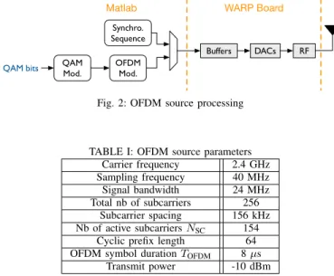
In this experimental test-bed, the OFDM source contin-uously transmits frames composed of a synchronization se-quence followed by OFDM data symbols, as depicted in Fig. 2. The OFDM signal parameters are summarized in table I. At
QAM Mod. OFDM Mod. Synchro. Sequence Buffers DACs RF QAM bits
Matlab WARP Board
Fig. 2: OFDM source processing
TABLE I: OFDM source parameters Carrier frequency 2.4 GHz Sampling frequency 40 MHz Signal bandwidth 24 MHz Total nb of subcarriers 256 Subcarrier spacing 156 kHz Nb of active subcarriers NSC 154
Cyclic prefix length 64 OFDM symbol duration TOFDM 8 µs
Transmit power -10 dBm
the tag side, as illustrated in Fig. 3, the signal processing is very simple. The reconfigurable antenna state of the tag i(l) is set via the configuration of GPIO pins accordingly to the bitsbi(l) to transmit. Note that the tag antenna is not fed by
an RF signal, and is therefore not generating any new radio wave.
Tag
Mod. GPIO
Matlab WARP Board
Reconf. antenna
b(l)
Fig. 3: Tag processing
At the receiver side, three steps are implemented in the test-bed. The first step consists in performing a frame de-tection in order to determine the beginning of the OFDM symbols. To this aim, a cross-correlation is carried out between the received samples and the synchronization sequence. The second step, consists in acquiring the N channels bHj,i(l)eq (k) (i(l) = 1, . . . , N ), as described in Section II. The last step, consists in detecting and demodulating the data transmitted bits, by first estimating the pattern index ˆi(l) according to (4) and then applying a simple demapping according to table II. Fig. 4 illustrates the implemented blocks.
For the OFDM source as well as for the receiver, omnidi-rectional monopole antennas with gain of 6 dBi are used.
RF ADCs Buffers DetectionFrame Demod.OFDM
RF ADCs Buffers Frame Detection
OFDM Demod.
WARP Board Matlab
Detector ChEst ChEst Y Demapping ˆi ! Heq X ! b
Fig. 4: Data demodulation processing
C. Tag antennas with reconfigurable radiation patterns In these experiments, a cross-polarized [9] and a Split Ring Resonators (SRR) [6] antennas are used. In order to generate several radiation patterns, the antennas are reconfigured by several external DC voltage bias. Here, the antennas are passive because the feeding point is connected to a constant passive load, i.e., 50. The backscatter symbols are then only coded through the different scattering diagrams of the tag. The presented antennas, initially developed for spatial modulation communication purposes, can generate efficiently up to 8 different radiation patterns at 2.45GHz. For each antenna, the four states (N = 4) that present the most different radiation patterns, i.e., showing the lowest spatial correlation factors are used. Therefore, the tag one can code log2(N ) = 2 bits per
symbol. In the following, the 2 antennas are described with its selected radiation patterns.
The cross-polarization antenna, depicted in Fig. 5, is based on two orthogonally printed meanderlines. On each side of a
Fig. 5: The reconfigurable cross-polar antenna
meanderline, two parasitic L-shaped resonators are etched on the lower face of the structure. Each of them is driven by a PIN diode that connects or disconnects them to the ground depending on the state of a 2-level DC voltage. In table II are shown the states of the 4 PIN diodes of the backscatterers for the 4 symbols. For each of them, this table provides also the corresponding sequencebiof 2 bits. The 4 patterns of the
cross-polarization antenna for each symbol are shown in Fig. 6. One can observe that the main lobes are oriented differently.
TABLE II: The 4 states cross-polar configuration and the corresponding mapping. Forward (F) and Reverse (R) modes correspond to a low and high equivalent impedance of the PIN diode respectively.
State index i D1 D2 D3 D4 Bits seq. bi
1 F R R R [00]
2 R F R R [01]
3 R R F R [10]
4 R R R F [11]
Fig. 6: Cross Polar antenna radiation patterns
The spatial correlation between the patterns is smaller than 19%.
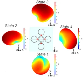
The SRR antenna, depicted in Fig. 7 is very different. It uses
Fig. 7: The split ring resonator antenna
a double closed rings as radiating element (not connected here to RF port). This magnetic moment dominates the behaviour of this element. The resonant frequency of the four parasitic open loops, shown in Fig. 7, are designed to efficiently couple with the radiating central element. Each of the 4 parasitic loops is driven by a PIN diode (in red) placed within the gap. Depending on the DC voltage applied, a parasitic loop acts as either as a reflector or a director of the incident wave. As for the previous structure, only four states that are the most
uncorrelated are used. The DC voltage on the diodes for the 4 states are the same than those presented in table II. The corresponding patterns are shown in Fig. 8. On can see that
Fig. 8: SRR antenna radiation patterns
the SRR antenna can steer the beam in four directions in space. The spatial correlations between the patterns vary between 5% (state 3 & 4) and 35% (state 1 & 3).
D. Measurements environment
All following measurements were performed in the reverber-ation chamber of IETR laboratory at INSA Rennes in France. Besides providing several multipath, the reverberation chamber has the advantage to provide a time invariant environment when its door is closed. Therefore by doing an ambient backscatter experiment inside it, the observed variation on the equivalent channelHj,i(l)eq will be only related to the state of the tag antenna. Furthermore, the amount of multipath can be reduced by adding some absorbers into the chamber. For these experiments, 5 absorbers are placed in the chamber. This allows to obtain a flat channel per OFDM subcarrier. Indeed, with 5 absorbers, the 70% coherence bandwidth at 2.4 GHz is above 650 kHZ [10], while the subcarrier spacing is about 150 kHz.
IV. EXPERIMENTAL RESULTS
In this section, we present experimental results obtained with the set-ups detailed in section III. The experimental setups of data transmission using the cross-polar and the SRR antenna are illustrated in Fig. 9 and 10, respectively. In both configurations, the source antenna and the NR = 3 receiver
antennas are spaced by 1 m, and the tag antenna is positioned between them at a distance of 40 cm from the receiver antennas. According to (1), a bit rate of 250 kbit/s is achieved by using the ambient backscatter transmission. In order to evaluate the BER of the tag transmission at the receiver side, 5000 OFDM symbols are transmitted per measurement leading to104bits transmitted using ambient backscatter modulation.
WARP boar
d
Source
antenna
Tag
antenna
Rx1
Rx2
Rx3
Absorber
Fig. 9: Experimental setup for the Cross-Polar antenna
WARP boar
d
Source
antenna
Tag
antenna
Rx1
Rx2
Rx3
Absorber
Fig. 10: Experimental setup for the SRR antenna
Due to these number of bits, only BER greater than 10−2
can be measured with precision. Therefore, when we observe no error during one measurement, we can only deduce that the actual BER is less than 10−2. For each tag antenna, BER
measurement is performed for NR going from 1 to 3. For
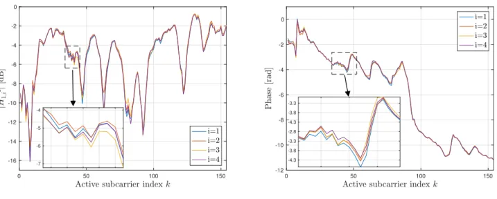
both configurations, the average signal-to-noise ratio (SNR) at the receiver side was measured and is equal to 28 dB. Under high SNR condition, the system performance is therefore mainly limited by the equivalent propagation channels cross-correlations as explained in Section II. An example of the equivalent channels bH1,ieq (i = 1, . . . , 4) estimated during measurement using the SRR antenna is presented in Fig. 11a for the module and Fig. 11b for the phase. As we can observe,
the estimated channels corresponding to the 4 states of the SRR antenna present almost similar frequency response. This is due to the fact that the reconfigurable scattering paths are weak compared to main paths and others reflections in the chamber. However, on both module and phase zoom, we can see that there is a slight difference between the estimated channels. As we can see in table III, which presents the experimentally BER for the 2 antennas with respect to NR,
this little difference is sufficient to demodulate the backscatter symbols. Indeed, a BER under10−2 is measured forNR= 3
using the SRR as tag antenna. For both antennas we observe that increasing the number of receive antennas improves the performance, as expected. We can also notice that the SRR
0 50 100 150 -16 -14 -12 -10 -8 -6 -4 -2 0 -7 -6 -5 -4 (a) Module 0 50 100 150 -12 -10 -8 -6 -4 -2 0 -4.3 -3.8 -3.3 -2.8 -4.3 -3.8 -3.3 (b) Phase
Fig. 11: Frequency response of the estimated channels bHj,ieq using the SRR antenna with i = 1, . . . , 4 and j = 1
TABLE III: BER measurements results Tag antenna NR Nb of erroneous bits BER
Cross-Polar 1 1562 1.6.10−1 2 1245 1.3.10−1 3 352 3.5.10−2 SRR 1 891 8.9.10−2 2 0 < 10−2 3 0 < 10−2
antenna, which has lower correlations than the cross-polar antenna, outperforms this latter. This result confirms our assumption that the scattering patterns correlation is related to the radiation patterns correlation.
V. CONCLUSION
In this paper, for the first time, we present a practical ambient backscatter communication with tags using compact antennas with reconfigurable radiation patterns to increase the bit rate. We experimentally test two different reconfigurable antennas: the so-called 4-states cross-polar antenna and the split ring resonator antenna that enable to achieve a modulation order of 4. Our measurement results show that the number of receive antennas improves the detection performance and that the split ring resonator antenna outperforms the cross-polar antenna. This latter result can be explained by the lower cross-correlation between radiation patterns observed for the SRR antenna than for the cross-polar antenna. Next studies will verify the link between antennas radiation patterns and scattering patterns, and their impacts on such system performance.
VI. ACKNOWLEDGEMENT
This work has been performed in the framework of the SpatialModulation project funded by the French National Research Agency (ANR) under grant NR-15-CE25-0016. This work was also supported in part by the European Union
through the European Regional Development Fund, in part by the Ministry of Higher Education and Research, in part by the R´egion Bretagne, and in part by the D´epartement d’Ille et Vilaine and Rennes M´etropole, through the CPER Project SOPHIE/STIC & Ondes.
REFERENCES
[1] A. Gati and et. al., “Key technologies to accelerate the ict green evo-lution: An operators point of view,” in Submitted to IEEE Communica-tions Surveys & Tutorials, available at https://arxiv.org/abs/1903.09627, 2019.
[2] V. Liu, A. Parks., V. Talla, S. Gollakota, D. Wetherall, and J. R. Smith, “Ambient backscatter: Wireless communication out of thin air,” in SIGCOMM 2013, 2013.
[3] G. Yang and Y. Liang, “Backscatter communications over ambient ofdm signals: Transceiver design and performance analysis,” in 2016 IEEE Global Communications Conference (GLOBECOM), Dec 2016, pp. 1– 6.
[4] C. Kang, W. Lee, Y. You, and H. Song, “Signal detection scheme in ambient backscatter system with multiple antennas,” IEEE Access, vol. 5, pp. 14 543–14 547, 2017.
[5] D.-T. Phan-Huy, Y. Kokar, K. Rachedi, P. Pajusco, A. Mokh, T. Magounaki, R. Masood, C. Buey, P. Ratajczak, N. Malhouroux-Gaffet, J.-M. Conrat, J.-C. Prvotet, A. Ourir, J. De Rosny, M. Crussiere, M. Helard, A. Gati, T. Sarrebourse, and M. Di Renzo, “Single-carrier spatial modulation for the internet of things: Design and performance evaluation by using real compact and reconfigurable antennas,” IEEE Access, vol. 7, pp. 18 978–18 993, 2019.
[6] K. Rachedi, D.-T. Phan-Huy, A. Ourir, and J. De Rosny, “Reconfigurable split ring resonators for spatial modulation communications,” in EUCAP 2019 - European Conference on Antenna and Propagation, April 2019, pp. 1–2.
[7] A. Ourir, K. Rachedi, D.-T. Phan-Huy, C. Leray, and J. de Rosny, “Compact reconfigurable antenna with radiation pattern diversity for spatial modulation,” in 2017 11th European Conference on Antennas and Propagation (EUCAP), March 2017, pp. 3038–3043.
[8] “Warp project,” http://warpproject.org.
[9] K. Rachedi, A. Ourir, D.-T. Phan-Huy, and J. De Rosny, “Reconfig-urable compact antenna for spatial modulation mimo communications,” International Journal on Communications Antenna and Propagation (IRECAP), vol. 9, p. 218, 06 2019.
[10] M. Andri´es, P. Besnier, and C. Lemoine, “On the prediction of the average absorbing cross section of materials from coherence bandwidth measurements in reverberation chamber,” International Symposium on Electromagnetic Compatibility - EMC EUROPE, pp. 1–6, 2012.