HAL Id: hal-01901612
https://hal.archives-ouvertes.fr/hal-01901612
Submitted on 23 Oct 2018
HAL is a multi-disciplinary open access
archive for the deposit and dissemination of
sci-entific research documents, whether they are
pub-lished or not. The documents may come from
teaching and research institutions in France or
abroad, or from public or private research centers.
L’archive ouverte pluridisciplinaire HAL, est
destinée au dépôt et à la diffusion de documents
scientifiques de niveau recherche, publiés ou non,
émanant des établissements d’enseignement et de
recherche français ou étrangers, des laboratoires
publics ou privés.
Internet of Mobile Things: Overview of LoRaWAN,
DASH7, and NB-IoT in LPWANs standards and
Supported Mobility
Wael Ayoub, Abed Samhat, Fabienne Nouvel, Mohamad Mroue,
Jean-Christophe Prévotet
To cite this version:
Wael Ayoub, Abed Samhat, Fabienne Nouvel, Mohamad Mroue, Jean-Christophe Prévotet. Internet of
Mobile Things: Overview of LoRaWAN, DASH7, and NB-IoT in LPWANs standards and Supported
Mobility. 2018 25th International Conference on Telecommunications (ICT), Jun 2018, St. Malo,
France. �10.1109/COMST.2018.2877382�. �hal-01901612�
Internet of Mobile Things: Overview of LoRaWAN, DASH7, and
NB-IoT in LPWANs standards and Supported Mobility
Wael Ayoub
∗†, Abed Ellatif Samhat
†, Fabienne Nouvel
∗, Mohamad Mroue
†and Jean-christophe Pr´evotet
∗∗Institut National des Sciences Appliqu´ees de Rennes — IETR-INSA, Rennes, France. †Faculty of Engineering - CRSI, Lebanese University, Hadath Campus, Hadath, Lebanon
Email∗: firstname.lastname@insa-rennes.fr Email†: samhat@ul.edu.lb, mohamad.mroue@ul.edu.lb
Abstract—Low-power Wide Area Networks (LPWANs) con-stitute a type of networks which is used to connect things to the Internet from a wide variety of sectors. These types of technologies provide the Internet of Things (IoT) devices with the ability to transmit few bytes of data for long ranges, taking into consideration minimum power consumption. In parallel, IoT applications will cover a wide range of human and life needs from smart environments (cities, home, transportation etc.) to health and quality of life. Among these popular LPWANs technologies, we have identified the unlicensed frequency band (LoRa, DASH7, SigFox, Wi-SUN, etc.), and the licensed frequency band standards (NB-IoT, LTE Cat-M, EC-GSM-IoT, etc.). In general, both types of standards only consider fixed interconnected things, and less attention has been provided to the mobility of the things or devices. In this paper, we address the mobility of the things and the connectivity in each of the three LPWAN standards: LoRaWAN, DASH7, and NB-IoT. In particular, we show how the mobility of things can be achieved when transmitting and receiv-ing data. Then, we provide a general and technical comparison for the three standards. Finally, we illustrate several application scenarios where the mobility is required, and we show how to select the most suited standard. We also discuss the research challenges and perspectives.
Index Terms—IoT communication, LPWAN, LoRaWAN, DASH7, NB-IoT, Long-Range, Mobility.
I. INTRODUCTION
Throughout the last few years, Internet of Things (IoT) has attracted the attention of both industry and research commu-nities in particular with the rise of Low Power Wide Area Networks (LPWANs) [1–3]. The IoT is sensitive to sustainable development [4] that will form a smart and comfortable future. IoT promises an interconnected network of smart things or objects including sensors, cameras, consumer electronic devices, etc. By 2020, there will be over billions of smart things connected to the Internet with a high potential economic impact, according to Cisco’s expectation [5]. This will enable the integration of the software agents on the Internet and will make the interaction of the real world and the virtual world possible [6]. Adding to that, in [7], they predict that there will be more than 20.8 billion of smart things connected to the Internet by 2020, whereas the worldwide number of connected devices was 6.4 billion in 2016. This growth is expected to continue to be exponential over the next decade, which introduces a rise in ”Big Data” [8], energy consumption [9] and devices per cell [10]. Today, a wide range of data acquisition devices is already implemented in IoT applications
[11], [12], that require mobility such as smart cities [13–15], health-care [16], [17], smart vehicles [18], aging society [19], hospital [20], [21], and in post-emergency networks [22]. In such applications, the requirements for mobility, low latency, and long-range communication are significantly considerable [23]. For that, we will distinguish applications that require mobility and dynamic change of location from the rest of IoT applications with the term Internet of Mobile Things (IoMT) [24].
LPWANs describe a category of wireless communication technologies designed to support IoT deployments. LPWANs represent a new phenomenal model in communication that complements between cellular and short wireless technologies to address the diversity of IoT applications. These technologies are designed to offer a set of features including wide-area and massive scale connectivity [25] for low power, low cost, and low data rate devices.
One of the emerging protocols in this scope is the Long Range Wide-Area Network (LoRaWAN). LoRaWAN is one of the most popular and successful technologies in the LPWANs space. LoRaWAN consists of a protocol stack specified by LoRa Alliance [26] that operates over the Long Range (LoRa) physical layer on unlicensed bands. The LoRaWAN features are low data rate, low complexity, different operating classes for various applications. It may exhibit an immense number of nodes per single gateway. In 2015, LoRaWAN v1.0 was declared by LoRa Alliance. In October 2017, LoRa Alliance announced LoRaWAN v1.1.
Another well-defined LPWAN standard is the DASH7 Al-liance Protocol (D7AP). D7AP is an open source Wireless Sensor and Actuator Network protocol (WSAN). It operates in the Sub-1 GHz bands based on the ISO/IEC 18000-7 standard and specified by DASH7 Alliance. The ISO/IEC 18000-7 standard defines the parameters of the active air interface communication at 433 MHz. D7AP inherits the default parameters [27] from ISO 18000-7 and extends the standard by specifying a complete communication stack from the application layer to the physical layer. This stack con-tains a high level of functionality optimized for active RFID and WSAN. Also, it ensures interoperability among different operators. Conversely to legacy RFID systems [28], D7AP supports tag-to-tag communication. In 2013, the D7AP 0.2 was announced by the DASH7 Alliance. In April 2016, the
DASH7 Alliance published D7AP 1.1 [29].
Regarding cellular systems, there are several LTE releases [30], [31] focusing on low-power wide-area IoT connectivity. In Rel-12, LTE introduces low-cost devices comparable to GPRS [32], [33]. Pacing to support narrow-band machine to machine communications (MTC), LTE has introduced some key features in Rel-13. EC-GSM-IoT [34] and LTE-MTC [35] aim to enhance existing GSM and LTE networks. Their aim is to support ”Rich IoT nodes and gateways” and ”Mainstream” IoT applications. These types of applications are out of the scope of this paper and we only consider ”constrained” IoT ap-plications. Narrowband IoT (NB-IoT) [36] is based on existing LTE functionalities. This standard is optimized to achieve low-cost, ultra-low complexity, and indoor improvement coverage. It supports a huge number of devices per cell-site sector, low-power consumption, low-data-rate, and latency less than 10 seconds. NB-IoT has been developed to operate in three modes: in-band, guard-band, and stand-alone.
Whereas LoRaWAN and DASH7 use unlicensed frequen-cies that are globally available, NB-IoT uses the same fre-quencies as LTE which is implemented worldwide. Those standards are developed to satisfy the needs of constrained IoT communication requirements. However, they almost consider static interconnected things and pay less attention to the mobility of things.
In this paper, we present an overview of the three LP-WAN standards: LoRaLP-WAN, DASH7, and NB-IoT including architectures, specifications, and communications. Also, we provide a general and technical comparison between the three standards regarding deployment, coverage, cost, QoS, battery life, latency, and mobility. Motivated by the mobility and the connectivity requirements, we investigate in particular the three different LPWAN technologies regarding mobility support. Thus, we show how mobility could be achieved and describe the encountered limitations. Then, we illustrate several application scenarios and determine how to select the most suited standard.
The rest of this paper is organized as follows. Sections II, III, and IV give an overview of LoRaWAN, DASH7, and NB-IoT respectively and provide the necessary background information that will be intended to address mobility. In Section V, we focus on the mobility achievement of the movable things in both cases, when transmitting or receiving data. In section VI, we present a comparative study of the investigated standards regarding deployment, coverage, QoS, etc. Finally, Section VII provides a conclusion and discusses the future works.
Fig. 1. LoRaWAN Protocol Architecture
TABLE I
LORA PROTOCOLSPECIFICATIONS
Specification LoRa Technology Support Standard LoRa Alliance
Operational Frequencies Unlicensed ISM band 868, 915 MHz Modulation Chirp spread spectrum (CSS) Coverage Range (Km) 2 - 5 (urban) / 15 (rural) Data Rate (kbps) 0.3 - 50 (EU) / 0.9 - 100 (US) Topology Star
II. LORAWAN IOT TECHNOLOGY
LoRaWAN is an open standard architecture developed by LoRa Alliance [26] to provide a medium access control mech-anism and enable End-Devices (ED) to communicate with one or more gateways. LoRa is a physical layer technology that enables long range, low data rate, and low power wireless communication. It is an unlicensed band technology that modulates the signals in the sub GHz ISM band using the spread spectrum technique [37]. It was developed by Cycleo [38] and commercialized by Semtech [39], Microchip, and others. LoRa can also be applied in P2P communications between nodes. Table I shows the specifications of the LoRa protocol. LoRaWAN constitutes a data link layer protocol above the LoRa physical layer protocol as shown in Figure 1.
A. Architecture
LoRaWAN Alliance uses a star network topology, in which a gateway seamlessly relays messages between a Network Server (NS) and ED as shown in Figure 2. EDs use LoRa to communicate with Gateways (GW). GWs use IP network (Ethernet, 3G, WiFi, etc.) to communicate with the server. Communication between the devices and gateways is spread out on different frequency channels, and data rates are de-termined according to communication range and message duration. This selection can be managed by a LoRaWAN network infrastructure, which selects the data rate and channel for each device using an Adaptive Data Rate (ADR) scheme [26].
Fig. 2. LoRaWAN System Architecture
• End-Device (ED): can be anything that sends or receives
information. There is no real definition of an ED, but it usually refers to sensors, detectors, actuators and where sensing and controlling take place.
• Gateway (GW): is also called modem or access point. It is used to forward messages from/to the ED and NS. In LoRaWAN, EDs are not linked with the GW. Instead, any message from an ED received by the GW will be delivered to the NS.
• Network Server (NS): is the most intelligent part of the LoRaWAN network. It is responsible for:
– Monitoring the GW and ED. – Aggregating the incoming data.
– Routing/forwarding incoming messages to the corre-sponding application server.
– Removing duplicates: remove duplicate messages received from one ED through multiple GW. – In the downlink, selecting one GW based on the
higher Received Signal Strength (RSS).
– Buffer downlink messages: is used to store downlink messages until the intended ED wakes up.
• Application Server (AS): It represents the application for a developer or manufacturer to parse the messages received from an ED. For example, in a cooling system application, if the temperature rises over 25◦c, it may decide to turn on the A/C to decrease it.
B. LoRaWAN Communications
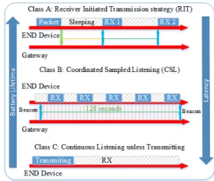
The LoRaWAN Alliance specifications define three classes for an ED, as shown in Figure 3. These classes have different capabilities to cover a wide range of applications. Each class constitutes a trade-off between battery life and network down-link communication latency. Based on the requirements, an ED can switch between classes, but class A must be implemented on all devices, by default.
1) Classes: The three classes are:
• Class A (Bi-directional EDs): it is the most energy efficient class, where an ED stays most of the time in the sleeping mode. Following every uplink phase, there are two downlink windows RX1 and RX2 to receive data with a latency of 1 second for each approximately [40].
• Class B (Bi-directional EDs with scheduled receive slots):
it is the same as class A, but devices listen to incoming messages on regular intervals synchronized with a bea-con.
• Class C (Bi-directional EDs with maximal receive slots): in this class, devices continuously listen for incoming messages unless transmitting (no latency). This class is used for real-time applications, where power is not constrained.
2) Connection Establishment with Security: To achieve security and integrity of the uplink and downlink messages between an ED and the GW and to preserve the NS time from reading messages contents that are relevant to another network or infrastructure, LoRaWAN defines two different keys used
Fig. 3. LoRaWAN End-device Classes Communication
during usual message exchange as shown in Figure 4. These two keys are:
• The Network Session Key (NwkSKey): It is used to encrypt the whole frame shown in Figure 5 (headers + payload) in case a MAC-command is sent. When data are sent, this key is used to sign the message which allows the NS to verify the identity of the sender.
• The Application Session Key (AppSKey): It is used to encrypt the payload in the frame. This key does not need to be known by the NS. The AS decrypts the information using the same key.
Fig. 4. Communication Exchanging and Security
3) Join the network: An ED cannot participate within the LoRaWAN network unless it has been activated. To activate the device, three types of information are required:
• Device Address (DevAddr): It consists of a 32-bit iden-tifier which is unique within the network. This address is equivalent to an IP address on a TCP/IP network. It is present in each data frame as shown in Figure 5. This key is shared between ED, NS, and AS.
• Network Session Key (NwkSKey) mentioned above: It consists of a 128-bit AES encryption key that is unique per NS. This key is shared between an ED and the NS; it
is used to provide message integrity and security for the communication.
• Application Session Key (AppSKey) mentioned above: It is a 128-bit AES encryption key that is unique per AS. This key is shared between an ED and the AS. It is used to encrypt and decrypt application data messages and to provide security for the application payload.
An ED can be activated to join the network using two methods. In both methods, the ED unique ID (DevEUI: is a 64-bits address equivalent to MAC address) should be known by the server before activation according to two schemes:
• Activation By Personalization (ABP): The shared keys are stored in the ED. When the ED is turned on for the first time, it can directly initiate the communication. This type of activation does not provide roaming between different network providers.
• over the Air Activation (oTAA): an ED performs a
join procedure to connect to a LoRaWAN network and exchange data. In this procedure, the ED exchanges two MAC messages with the server: Join request and Join accept. During the join procedure, an ED is assigned a dynamic device address (DevAddr) and security keys are negotiated with it. This procedure is repeated every time the ED looses the connection. In this way, an ED can roam between LoRaWAN networks of different operators. This method is preferred to achieve mobility.
Fig. 5. LoRa Uplink PHY structure and Frame
4) Communication: After activation, an ED joins the Lo-RaWAN network and starts to send/receive data messages. These messages are used to transfer both MAC commands and application data, which can both be combined in a single message. LoRa allows an ED to use any possible data rate to transmit the message using an Adaptive Data Rate (ADR) scheme. This scheme is used by the network or the ED
application layer to manage, adapt, and optimize the data rate of a static ED to provide the highest possible data rate. If this scheme is not enabled, the network will not control the data rate even if the received RSSI is low. In this case, the device application layer is responsible for managing the data rate. Note that this is not efficient when the radio channel attenuation changes continuously in a fast manner. An ED can benefit from the ADR scheme to increase the battery life and to maximize network capacity.
An ED and AS can request a confirmation for the mes-sage. Confirmed-data messages must be acknowledged by the receiver whereas unconfirmed-data do not require acknowl-edgement. In case of Figure 6 (a), the ED transmits an acknowledgement at its discretion, since the ACK is a sending operation (uplink) concerning ED. In case of Figure 6 (b), the network will send the acknowledgement using one of the receive windows opened by the ED after the sending operation. Acknowledgements are only submitted in response to the last received message and are never retransmitted.
Fig. 6. Acknowledgment Message
Finally, downlink messages at physical layer are similar to uplink ones but without the CRC field, meaning that there is no payload integrity check (see Figure 7). This is to keep the message as short as possible to guarantee a minimum impact on any duty-cycle limitations of the used ISM band.
Fig. 7. LoRa Downlink PHY Structure
III. DASH7 IOT TECHNOLOGY
The DASH7 Alliance (D7A) [41] is an open source active RFID standard for WSAN protocol. D7A complies with the ISO/IEC 18000-7 standard. ISO/IEC 18000-7 is an open stan-dard for the license-free 433 MHz ISM band air-interface for wireless communications. The 433 MHz frequency provides D7A with long propagation distance and better penetration. A full OSI stack (7 OSI layers) known as D7A protocol (D7AP) is specified [29]. It provides a long range (up to 2 Km), and low latency with multi-year battery life to connect moving objects. Table II shows the specifications of DASH7 wireless technology.
D7A is named as BLAST network technology. The D7A features are:
TABLE II
D7A PROTOCOLSPECIFICATIONS
Specification DASH7 Technology Support Standard Inherited ISO/IEC 18000-7 Operational Frequencies 433.92, 868, 915 MHzUnlicensed ISM band Modulation 2-GFSK
Coverage Range (Km) 1 - 2 (extend using subcontroller) Data Rate (kbps) 13, 55, 200 (16, 8, 4 channels) Topology Tree, Simple routing 2 hops
• Light: Small packet size limited to 256 bytes.
• Asynchronous: Communication is command response
based, no periodic synchronization.
• Stealth: ED communicates with pre-approved GW. No
need for periodic discovery beacons. This feature will be discussed in mobility section when ED moves out from the coverage of the current GW.
• Transitive: Supports mobility. ED can move seamlessly between different GWs coverages.
Fig. 8. DASH7 Alliance Protocol Architecture
In this part, the DASH7 Alliance protocol communication is presented along with the different layers concern with mobility to clarify the role of each one in the communication. In the uplink, EDs use CSMA/CA method which is illustrated in the physical layer. In downlink, EDs use the scan automation process that is illustrated in the data link layer. Sent/received data and ED address are presented in the Network layer section.
A. Architecture
For some basic elements, The D7AP architecture is similar to LoRa. It consists of EDs and GWs as shown in Figure 8, and can include sub-controllers. The v1.1 specification of D7A divides the devices into three classes as shown in Table III. An ED is a simple device consisting of sensors and/or actuators with a transceiver. It gathers information and sends it to a GW when required in asynchrony mode. This device is designed to operate with minimum energy consumption (low power) and to sleep most of the time. It does not contain all D7AP features, and it uses periodic wakeup method to listen to possible incoming packets. A sub-controller device is similar to an ED and can be used as a relay for packets between an
ED and a GW. However, all D7AP features are implemented on the sub-controller device. A GW also implements all D7AP features and is always in receiving mode unless transmitting. It receives data from an ED, processes them, and forwards them to the IP-Network or transmits them to another DASH7 network. The NS shares the same features and functions as the NS in LoRaWAN, it aggregates the received data, removes duplicates when necessary, and selects the nearest GW for an ED in the downlink. Finally, the customer cloud is a program or code executed at the edge of the network. It receives the data and updates or configure the ED. Customer cloud is similar to AS in LoRaWAN.
TABLE III D7ADEVICES CLASSES. Device Class TX RX Complete Feature Set Wake-on scan cycle Always on receive Endpoint X X X Subcontroller X X X X Gateway X X X X
Fig. 9. DASH7 Alliance Protocol Communication Model
B. D7AP Communications
In D7AP, the communication between EDs and GWs is defined as two models shown in Figure 9. First, the pull model is a request/response mechanism. It is described by the D7A query protocol data transfer (Network layer protocol). The GW initializes it, and it is applied between the GW and the ED (More details will be given in section III-B3). The second is the push model that uses the D7AP Action Protocol (D7AActP) (Application layer protocol). D7AActP is used by an ED to send data to the GW using tag-talks-first scheme. The advantages of the push model come from the fact that it is effective in many cases to push the data. Moreover, it provides low power consumption with efficient usage of the spectrum. D7A specifications make a correspondence between the D7A protocols and the OSI layers. D7A protocol layers are defined as follows:
1) Physical layer (PHY): This layer encompasses the mod-ulation, spectrum and channel coding characteristics [29]. All data traffic in D7A has the frame structure shown in Figure 10. The packet incorporates the power ramp-up and ramp-down
that are used to meet the bandstop channel requirements. The preamble consists of a series of binary symbols (32-bit for base & normal or 48-bit for high-rate & blink channels) that are used to calibrate data rate circuits on the receiver. Sync Word is a 16 binary symbols block used to align the packet payload that contains the data defined by the upper layers. The
Fig. 10. D7A General Frame Structure [29]
protocol defines different channel classes: low-rate, normal and high-rate as shown in Table IV.
TABLE IV
D7AP MODULATIONSCHEMES USING2-(G)FSK [42] Channel Class Channel Spacing (MHz) Symbol Rate (kbps) Modulation Index Frequency Deviation (KHz) Lo-Rate 0.025 9.6 1 ± 4.8 Normal 0.200 55.55 1.8 ± 50 Hi-Rate 0.200 166.67 0.5 ± 41.667
EDs use CSMA/CA method to access the channel and transmit data. Before starting the transmission process an ED guards (reserves) the channel, as shown in Figure 11, for the period of transmission. This period is extended if the transmission time is greater than or equal to the guard interval (TG). The channel guard is extended by TG after the
transmission, but if the transmission time is less than TG, there
is no extension. In addition, let TT be the minimal duration
of the silent period between two transmissions, and TS be the
silent period, we have TT < TS < TG. The values of the
channel guarding constants are given in Table V.
TABLE V
CHANNELGUARDINGCONSTANTS
Constant
Parameter Description
Value Ti=(∼0.977 ms) TG Channel Guarding Interval 5 Ti
TT Channel Turnaround Interval 2 Ti
2) Data Link Layer (DLL): This layer specifies the data link addressing; The fixed unique ID (UID) is a 64-bit value and must be unique to every D7A device. The dynamic network-unique virtual ID (VID) is a 16-bit ID supplied by the network administrator which is unique within the network. DLL defines the transmission, reception, scan automation and multiple access processes. Two types of frames shown in Figure 12 are held in this layer:
• Background frame: a fixed length 6-byte frame, preceded by a sync word of class 0.
• Foreground frame: a variable length, up to 255 bytes, preceded by a sync word of class 1.
A subnet parameter consisting of bit specifier and a 4-bit mask is used to filter the incoming frames. Each device contains an internal subnet value known as the device subnet which is compared with the value of the received frame subnet known as frame subnet. A Cyclic Redundancy Check (CRC) is used to check the integrity of the frame. The Target Address (TADR) parameter holds the address of the destination. The type of address used (UID or VID) on TADR is specified in the first 2 bits of the CTRL parameter, which also holds the estimated radiated power of the transmitter in the following 6 bits.
DLL defines the first level frame filtration, where three steps filter incoming frames are:
• Cyclic Redundancy Check (CRC16).
• Subnet matching and link quality.
• Device ID matches. newline
Device to Device Communication
The D7A protocol also supports device to device commu-nication, which is defined in this layer using the concept of Access Profile (AP) and Access Class (AC). AP defines the subnet, transmission time-out, period of automatic scanning, and the number of the sub-bands to scan or transmit on. Table VI shows the parameters that allow accessing a remote device through a channel scanned by the latter device. It is composed of 4 sub-profiles and a list of 8 sub-bands. All the sub-bands share the same channel header and allow the node to communicate on a group of channels. A sub-profile is a combination of the sub-bands and a scheduling time as shown in Table VII. This combination is described in the one-byte bitmap. The AC is divided into two fields: the Access Specifier (AS) and the Access Mask (AM), as shown in Table VIII. AS is the index of the D7A file. This file contains the AP. The APs are not exchanged between devices, and only the ACs are transferred. Before deploying the network, the network administrator must set up the AP, sub-profiles and has to link an AC to each profile. This configuration must be known by all devices in the network and be unique.
To communicate with Device B, Device A must use the AC of Device B. The application layer of A provides the address of B to initiate a dialog using one of the channels that B scans [29] (refer to specification v1.1 section 7.3 and subsection 8.4.5). Device B, using its own AC, will scan the associate channel list during the automated scan routine every TSCHED ms. If B detects the message, a dialogue will be
opened between them to exchange requests and responses (B extracts the address of A from the ”Origin” field in D7ANP network layer) and it will be closed when they finish. In case Bchanges its class, A is no more able to communicate unless Binforms A about the changes or B initiates a dialog with A. In the D7A specification, there is no indication of how this notification is performed. But all packets sent by a device contain the AC, so if A receives a packet from B, it will get the new class of this device.
newline-newline-newline-newline-newline-newline-newline-newline-newline-newline
Fig. 11. Channel Guarding
Fig. 12. Foreground and Background Frame Structure TABLE VI ACCESSPROFILE Parameter Size (byte) Description CH 1 Channel Header SP 4x2 Sub-profiles 0 to 3 SB 8x7 Sub-bands 0 to 7
Scan Automation Process
EDs use scan automation process to receive data messages. Scan automation defines scan timeout, foreground scan, back-ground scan, reset and restart.
Scan Timeout: To specifies the duration of the period during
which a device tries to receive a DLL frame. If the value of To is not defined by a DLL scan automation process or upper
layer, its value will be dependent on the channel class, the timing tolerance of the device, and the maximum length of the PHY packet preamble.
Foreground Scan : If TSCHED= 0, the device will
continu-ously scan the channel list, in parallel. This scan is only paused when the upper layer preempts the DLL frame to transmit or receive. In this case, scan timeout (To) will be set to 0.
Background Scan : If TSCHED> 0, an independent schedule
is set to generate a regular scan, it starts events at the TSCHED
rate. When the device cannot run the scan automation, these scans events will be masked. A background scan of the scan automation channel list is started on every unmasked scan
TABLE VII ACCESSSUB-PROFILE
Sub-band Bitmap 1 byte Bitmap of used sub-bands TSCHED 1 byte Scan automation period(compressed format)
TABLE VIII ACCESSCLASS
b7 b6 b5 b4 b3 b2 b1 b0 Access Specifier Access Mask
event. Upper layers select the value of T0.
Reset and Restart: The scan resets
• when the scan automation channel list is consumed. • stopped by the upper layer to transmit or receive. After the scan resets, it is restarted
• immediately if TSCHED= 0
• at the next scheduler event if TSCHED> 0
3) Network Layer (NWL): This layer defines the back-ground network protocol, and the foreback-ground network proto-col.
The D7A Advertisement Protocol (D7AAdvP) is a transmission-only background network protocol (pull com-municational model). It is used for rapid and ad-hoc group synchronization. D7AAdvP is defined in D7AP as a low-power wakeup mechanism used by a gateway or a sub-controller to query EDs. The GW or sub-controller starts by continu-ously transmitting the D7AAdvP to flood the channel with background advertising frames for a duration that depends on the EDs AP [29]. Each frame contains the Estimated Time of Arrival (ETA), which is the time to send the fore-ground frame that includes the Application Layer Protocol (ALP) command. This value is decremented in the subsequent background advertising frames until reaching zero. EDs are
configured to schedule a background scan (frame of class 0) at a specific rate. At a particular time that corresponds to each ED configuration, an ED wakes up and starts listening by scanning the channel for incoming background frame. When the frame is received, the ED extracts the ETA value and returns to sleeping mode until the time (ETA) is elapsed. Then, the ED wakes up and scans for foreground frames (frame of class 1) to receive and respond the request. This mechanism leads to very low power consumption for ad-hoc synchronization. Synchronization train is shown in Figure 13.
The foreground network protocols are used for responses, queries and beacons:
• D7A Network Protocol (D7ANP) is an addressable
(uni-cast, broad(uni-cast, multicast and any-cast), and routable pro-tocol. It is used by D7A Query Protocol in the transport layer. It supports two-hop routing and security in the network layer.
• D7A DataStream Protocol (D7ADP) which is used by the ALP, is a generic data encapsulation protocol. This protocol does not contain information about routing or addressing.
Fig. 13. Synchronization Train Chain [29]
4) Upper Layers: The Transport Layer (TPL) provides end-to-end communication services. It defines the concept of request-response, and a method for acknowledging single and group requests.
The Session Layer (SEL) indicates which events may trigger session initiation or scheduling. It defines the concept of QoS and the method for queuing, transmitting, re-transmitting, scheduling, and receiving upper layer requests.
The ALP contains the application API. The latter defines a standard method to manage Data Elements by the application.
IV. NB-IOT TECHNOLOGY
Narrow Band Internet of Things (NB-IoT) is a part of release 13 [36]. It was setup by 3GPP in Cellular systems in support for ultra-low complexity and low throughput Internet of Things (CIoT). It defines a new radio access technology that can be integrated into the LTE standard. NB-IoT is built from existing LTE functions, but many features have been removed to keep this standard as simple as possible to reduce device cost and minimize battery consumption. This optimization in-cludes removing handover, carrier aggregation, measurements to monitor the channel quality, and dual connectivity. NB-IoT operates on the same licensed frequencies used by LTE and employs QPSK and BPSK modulations. Table IX shows the specifications of NB-IoT.
Physical layer is designed to fit in 200 kHz system bandwidth used by both uplink and downlink. This enables NB-IoT to gain the feature of deployment in the GSM carrier as
standalone, and in LTE as in-band or guard-band as shown in the Figure 14.
• Standalone: Replacing a GSM carrier with an NB-IoT cell.
• Guard-Band: Benefit from unused resource blocks within the guard-band of LTE carrier.
• In-Band: Use one or more Physical Resource Blocks
(PRBs) that are reserved for NB-IoT.
Fig. 14. NB-IoT Deployment Modes [43]
TABLE IX
NB-IOT PROTOCOLSPECIFICATIONS
Specification NB-IoT Technology Support Standard 3gpp (release 2015) Operational Frequencies Same LTE band Modulation QPSK & BPSK Coverage Range (Km) <15 Data Rate (kbps) ∼50 Topology Star
A. Architecture
NB-IoT uses the same network architecture as in LTE network but with some optimizations to meet the requirements of IoT massive users. NB-IoT architecture is based on the Evolved Packet System (EPS) as shown in Figure 15. A new node has been added to the architecture, known as Service Capability Exposure Function (SCEF), which is designed for machine type data. Two optimizations are defined for CIoT in EPS: Control plane CIoT EPS optimization (red lines), and user plane CIoT EPS optimization (blue line). Both opti-mizations may be used for sending data to the correspondent application. On the user plane, the blue line, IP and non-IP data are transferred in the same way as for the conventional data traffic, i.e., over radio bearers via the Serving Gateway (SGW) and the Packet Data Network Gateway (PGW) to reach the application server. With the control plane, the red lines, the radio communications between the user equipment (End-Device) and MME are handled by the evolved UMTS terrestrial radio access network (E-UTRAN), which consists
TABLE X
CHANNELS ANDSIGNALS[45] Channel Usage UL
Narrowband Physical Uplink
Shared Channel (NPUSCH) Uplink dedicated data Narrowband Physical Random
Access Channel (NPRACH) Random access
DL
Narrowband Physical Downlink Control Channel (NPDCCH)
Uplink and downlink scheduling information Narrowband Physical Downlink
Shared Channel (NPDSCH)
Downlink dedicated and common data Narrowband Physical
Broadcast Channel (NPBCH)
Master information for system access Narrowband Synchronization
Signal (NPSS/NSSS)
Time and frequency synchronization
of the evolved based stations known as eNodeB or eNB (Gateway). Then, uplink data are transmitted to the SGW that forwards them to the PGW. Non-IP data will be sent using SCEF, which is the new node responsible for delivering non-IP data over control plane and providing an interface for the network services (authentication and authorization, discovery and access network capabilities).
Fig. 15. NB-IoT Architecture
There is no difference in the access network architec-ture compared to LTE [44]. The GW is connected to the MME and S-GW using the S1 interface as shown in Fig-ure 16. GWs are connected together with the X2 interface although there is no handover, this interface enables a fast connection resuming when ED change from IDLE STATE to RCC CONNECTION. This will be explained in the mobility section below.
Fig. 16. Network Architecture Towards the Air Interface [44]
B. NB-IoT Communications
In this subsection, we focus on the physical layer and resource mapping. A summary will be given to different channels and signals for downlink (DL) and uplink (UL) that are used by NB-IoT as shown in Table X.
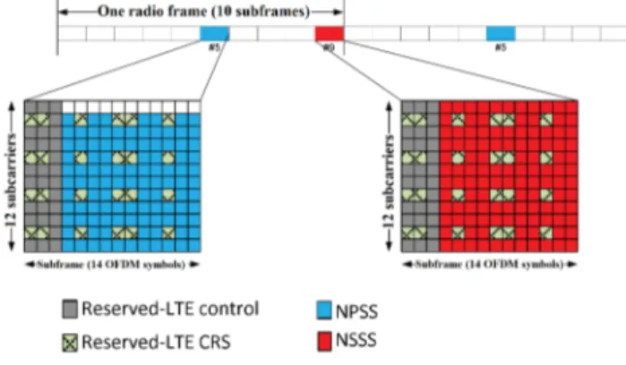
1) NPSS/NSSS: In case of in-band and guard-band mode, NPSS/NSSS signals can be only transmitted in the certain subset of the available LTE PRB locations, as shown in Figure 17. This is due to the frequency offset between the DC carrier and the centre of the NB-IoT carrier that should be held within ±7 kHz range, to ensure efficient cell searching. NPSS is transmitted every 10 ms and NSSS every 20 ms.
Fig. 17. Primary and Secondary Synchronization Signals Transmission [45]
2) NPBCH: It is responsible for transmitting the Narrow-Band Master Information Block (MIB-NB) over an 80 ms block. This transmission is repeated 8 times, where MIB-NB is transmitted precisely without any content change for 640 ms using QPSK modulation, to ensure that the block is received in extreme coverage conditions. Figure 18 shows the NPBCH transmission and the location of the NRS signals. MIB-NB is a 50-bits size block that contains 16-bit CRC and spare bits. This block is used to provide an NB-IoT ED with the main information like System Frame Number (SFN). Also, it provides the operational mode, channel raster, LTE Cell-specific Reference Signal (CRS), and System Information Block (SIB) scheduling.
Fig. 18. NPBCH Transmission [45]
3) NPDCCH: This channel is used to carry downlink con-trol information, like paging or system information. Depending on the used NPDCCH format as shown in Table XI, data
may be carried by one or an aggregation of two subsequent Narrow Band Control Channel Elements (NCCEs) during a frame. Each NCCF consists of six carriers in a sub-frame as shown in Figure 19. The search space defines which NPDCCH transmission sub-frame an ED is searching for. Repetition of transmissions is used in NB-IoT to achieve coverage enhancement. Depending on the coverage level, each ED is configured to transmit NPDCCH several times based on the Rmax which is chosen from up to 2048 (value 2n). The
number of repeated transmissions is also indicated in the DCI as illustrated in Table XII. Then, an ED can determine the end of the NPDCCH transmission when it successfully decodes the NPDCCH before the last repetition [45].
TABLE XI
NUMBER OF AGGREGATEDNCCES FOR EACHNPDCCHFORMAT
NPDCCH Format Number of NCCEs
0 1 1 2 TABLE XII DCI FORMATS DCI Formats N0 NPUSCH Scheduling N1 NPDSCH Scheduling and NPDCCH Order N2 Paging and direct indication
Fig. 19. CCE Allocation in NPDCCH (in-band operation mode) [45]
4) NPDSCH: This channel is scheduled after NPDCH, to give time to end-devices to decode NPDCCH. This delay, which is at least 4 ms, starts from the end of the NPDCCH to the beginning of NPDSCH and reduces the complexity of NB-IoT end-devices. NPDSCH employs the whole 12 sub-carriers in the downlink bandwidth. Only single HARQ process, which is adaptive and asynchronous, is supported in the downlink.
5) NPRACH: This signalling channel can be used by ED in the random access channel procedure for cell accessing, where the preamble is transmitted.
A preamble is based on a single sub-carrier of a single group, with frequency hopping for a single user as shown in Figure 20. Each symbol group has a Cyclic Prefix (CP) followed by five symbols. Hopping is between groups of
TABLE XIII NPDSHSPECIFICATIONS
Modulation only QPSK Maximum Transport
Block size (TBS) 680 bits Channel coding TBCC
Redundancy not supported Error detection Supported using 24-bit CRC Download Schemes Using one antenna port (port 0)
Using Space-Frequence block coding (SFBC) for two antenna port (port 0 and 1) Data Rate (kbps) Instantaneous Peak 170
Sustained Peak 26.2 Rmax 1, 2, 4, 8, 16, 32, 64, 128, 192, 256,
384, 512, 768, 1024, 1536, 2048
symbols whereas pseudo-random hopping concerns repetitions of groups. Different cell sizes can be achieved when using sub-carrier spacing of 3.75 kHz, with a symbol length of 267 µs, and two cyclic prefix lengths: 66.7 µs (10 Km) and 267 µs (35 Km). NPRACH has three resource configurations within a cell, each of which corresponds to a different coverage level. A resource configuration is given by:
• Periodicity.
• Number of repetitions, Up to 2048 and 128 times in DL and UL to enhance coverage.
• Starting time.
• Frequency location.
• Number of sub-carriers, it can be 12, 24, 36, 48.
Fig. 20. NPRACH channel [45]
6) NPUSCH: This channel is designed to carry uplink data and send HARQ Ack/Nack. It provides extended coverage, long battery life, and massive capacity. This channel has two formats: Format 1 is used to send uplink data (maximum transport block: 1000 bits). Table XIV shows the smallest amount of time-frequency resource units (RU). For RUs with one subcarrier, BPSK and QPSK may be used, while for all other RUs, QPSK is applied. Format 2 is used in signalling HARQ acknowledgement for the downlink channel NPDSCH. In this case, the modulation scheme is always BPSK. It always uses one sub-carrier with a length of 4 slots. In the case of a 3.75 kHz spacing, an RU has an 8 ms duration whereas in 15 kHz sub-carrier the duration is 2 ms. NPUSCH supports the following features:
• Large transport block.
• Time-domain repetition. It helps in extending coverage and channel estimation as explained before.
• Single-tone transmission (3.75 kHz or 15 kHz sub-carrier space), and multi-tone transmissions (15 kHz sub-carrier spacing).
• low peak-to-average-power ratio (PAPR) modulation schemes (π/2-BPSK and π/2-QPSK) for single-tone transmission. TABLE XIV NPUSCH RU DEFINITION Subcarrier spacing (kHz) Number of Tones Number of SC-FDMA symbols Transmission time interval (ms) 15 1 112 8 3 56 4 6 28 2 12 14 1 3.75 1 112 32
Protocol Stack: NB-IoT protocol stack starts with the protocol layers used in LTE protocols. These layers have been reduced and optimized to meet the requirements of NB-IoT. This protocol is built on a well-established fundamental and can be viewed as a new air interface technology. NB-IoT protocol stacks shown in Figure 21 look the same as for LTE but with optimized functionalities.
Fig. 21. NB-IoT Protocol Stack
System Information: These blocks are used to broadcast information for all EDs within the range of the GW. Table XV illustrates a set of SIBs used in NB-IoT and defines them. In case of system information acquisition or changes, ED is returned to the IDLE state if connected. Even if NB-IoT is deployed in-band with LTE, EDs will ignore SIBs from LTE.
V. MOBILITY MANAGEMENT
After presenting the specifications of LoRaWAN, DASH7 Alliance (D7A), and NB-IoT, we can note that the mobility has not been highlighted in those IoT environments. The requirement of mobility in such environments is different from the mobility management found in IETF [46] protocols.
TABLE XV
SYSTEMINFORMATIONBLOCKS CONTENT
System Information Block Content
MIB-NB receive further system informationEssential information required to SIBType1-NB Cell access and selection,
other SIB scheduling SIBType2-NB Radio resource configurationinformation SIBType3-NB Cell re-selection information for
intra-frequency, inter-frequency SIBType4-NB
Neighboring cell related information relevant for intra-frequency cell re-selection SIBType5-NB
Neighboring cell related information relevant for inter-frequency cell re-selection SIBType14-NB Access Barring parameters SIBType16-NB Information related to GPS time andCoordinated Universal Time (UTC)
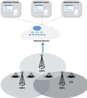
Mobility management in IP networks consists in providing seamless connectivity during IP handover (either soft or hard handover), whereas the mobility in IoT refers to ensuring the delivery of information on demand and during movement. In the following, we show the mechanism that ED of each technology follows to ensure data delivered while moving. In this section, we consider the mobility of an ED within those three technologies, i.e. when an ED is moving in an IoT environment. As stated above, beyond ubiquity of EDs in IoT environments, there is an increase in IoT applications that require mobility. ED may consist of a human carrying a smart phone, autonomous vehicle, robot, drone, etc. Thus, investigat-ing and supportinvestigat-ing mobility is a significant requirement for a wide range of IoT applications. Here, we mainly focus on the mobility of an ED moving within one technology, under different GWs that belonging to a single network operator as shown in Fig. 22. In the following, we will explain the switching procedure achieved by ED after losing connection with current GW, in order to connect with a new GW.
In the following, we denote by ” Uplink” the data frame transmitted from an ED to the GW, and by ” Downlink” the data frame that is transmitted from the GW to an ED. A typical scenario considered in this case is the handover of an ED from a gateway to another one in two cases: first, a message is transmitted in uplink and second, a message is transmitted in downlink to the ED. In the following, we investigate in details this scenario for the three IoT technologies: LoRaWAN, D7A, and NB-IoT.
A. LoRaWAN
In LoRaWAN, a GW is seamless to an ED, where an ED sends data when available without considering location change, movement, and speed of motion. On the second side, any GW that receives the message will forward it to the NS. In this protocol, to clarify mobility, we take into con-sideration the class of the node and the transmitting/receiving (uplink/downlink) process.
Fig. 22. Mobility scenario within IoT environment
1) Class A: An ED sends an Uplink message to an NS relayed by one or more GWs. Uplink messages can be sent at any time using the Aloha method. Any GW in the range of the ED that receives the message will forward it to the NS. The GW attaches the RSSI to every received message from any ED before delivering it to the NS. The RSSI value is used to indicate to the NS the nearest GW from the ED. A forward table is created on the NS that contains the ED and GW addresses. This table will be used later by the NS to forward a downlink message to an ED. LoRaWAN specifications (release 2016) do not describe the transmission of multicast messages from NS to more than one ED [26]. The message format at the physical layer is shown in Figure 5, where the radio transceiver inserts the LoRa Physical Header (PHDR), CRC header (PHDR CRC), and payload CRC field (used to protect payload integrity).
Two receive windows are opened by an ED after every uplink transmission to receive the downlink message. The NS sends the downlink message to the ED relayed by only one GW selected from the forward table. Data that are intended for a particular ED are queued in the NS until receiving a message from this device. This indicates that the device has wake-up and that two receiving windows have been opened. From the uplink message, an NS can determine the location of the device as explained previously. Then, the NS initiates the transmission just following one second after receiving uplink message from the ED. During one of the receive windows, if a preamble is detected, the radio receiver stays active until the downlink frame is demodulated. If an ED detects and demodulates the downlink message during the first receiving window, this ED will check the address and Message Integrity Code (MIC). If this message belongs to this ED, RX2 will not be opened, and the ED enters the sleep mode.
2) CLass B: It extends class A by adding synchronized reception windows. An ED is synchronized using the time-synchronization beacons transmitted by the GW. Class B is intended for mobile and fixed devices. The primary purpose is to have a synchronized device that listens on fixed time intervals to receive the messages. The decision of switching from class A to B is triggered from the application layer. If the network controls the decision, the application layer on the ED must be able to recognize the request of the application server for switching. When ED changes its place, it is configured to send an uplink message to the NS (even an empty message) to update its new location in the forwarding table of the NS. While location of ED changes to a GW that does not support class B, the ED directly switches to class A.
3) CLass C: An ED always listens on RX2 window slot unless it transmits or receives on RX1. Class C device imple-ments the same receiving windows (RX1, RX2) as class A, but the RX2 window is not closed unless transmitting as shown in Figure 23. A short RX2 window is also opened directly after the end of transmission and before the beginning of the RX1 receiving window, using the same frequency and data rate of RX2 . Any time NS sends a downlink message, a class C device can receive. When location changes, ED sends an uplink message to inform the NS about the changes.
Fig. 23. Class C end-device reception slot timing
4) Transmission and Retransmission Procedure: It is straightforward in LoRaWAN communication. When an ED has data to transmit, it just wakes up and sends. Class A uses Aloha method, and class B uses slotted Aloha method. Even if the device is moving (location changes), the ED only transmits data, and if any GW in the range receives the message, it will forward the data to NS. Acknowledgement can be used to verify that the message had been received, especially for important data. This is used to avoid data loss when transmitting during mobility. When an ED asks for ACK on the uplink message and ACK is not received, the ED will retransmit the message. In case 1, Figure 6 (a), the ED will retransmit message until:
• Receiving acknowledgment
• Reaching a maximum number of retransmission
It is up to the ED to choose whether to retransmit or forfeit that message and move on.
The ED tries to regain connectivity by lowering the data rate to increase the communication range. While lowest data rate is used, no action can be taken to improve link range.
In case 2, Figure 6 (b), the NS will retransmit the message until:
• Receiving acknowledgement
• Reaching a maximum number of retransmission (value specified for that ED during configurations)
As for the ED, the NS decides to retransmit or forfeit that message when the ED regains connectivity. As the number of EDs within the range of one GW increases, the uplink frames that require acknowledgements may cause collisions, and the radio network worsens the situation if their responses are not received. This is because EDs use Aloha access method and the retransmission method as explained previously.
Mobility in LoRaWAN can be achieved in uplink, when the device moves, changes the location, and can send data. This can be done using any of the three classes without latency as long as it is under the coverage of LoRaWAN network GWs. Whereas LoRaWAN uses broadcast for uplink, it is more difficult for downlink. The NS selects only one GW to send the message to the ED based on the forwarding table. When the ED moves and changes its location from the coverage of the current GW to another, the NS can no more reach it until a message is received from this device. Considering applications for which latency is constrained, the latency value changes between the three classes. In the downlink, when data are available on NS and ready to send, it will:
• Directly send the data if the ED is operating in class C.
• Send data on one of the pre-defined listen to time slots
if the ED is in class B.
• Send data directly when an uplink message is detected
from the ED of class A. B. DASH7 Alliance
In D7A, an ED selects one GW to communicate. It searches for a GW within the range and it chooses one to communicate with based on the signal strength. When moving, the ED sends the previously sent data to the same GW. In this case, the ED will not receive any acknowledgement and will detect that the connection is lost due to the location change.
1) Transmission (Uplink) Processes:
In DASH7 the connection is sprightly and straightforward as LoRaWAN. A device uses the CSMA/CA process to transmit a message and will guard the channel before transmission. An ED will communicate with any GW that acknowledges its message. In case the connection is lost with the current GW, the ED will send the next message as broadcast, and it will communicate with the GW that responds to the message. If multiple gateways respond, the ED will choose the best gateway according to link budget (RSS) and start the com-munication with it in a unicast manner until the connection is lost again. If the ED does not use security, it can communicate with any GW in range. But if network security is implemented, the device can communicate with only the GWs that share the same network key. Network keys are currently pre-shared. The D7A protocol specifications do not include a way or method to assign the keys, but programmers are free to implement their own plan.
2) Reception (Downlink) Processes:
In the downlink, an ED may receive two types of frames: Background and Foreground frames. Also, there are two ways for communication: Pull and Push. Background frames are sent by the GW to an ED for group synchronization using the pull method. Foreground frames are used for request/response between the ED and GW or two EDs using either push or pull. In the following, we will explain each frame reception process and conclude on how mobility can be achieved.
Fig. 24. Background Reception Process
Background Scan and Message Reception: As illustrated in Figure 24, an ED searches periodically for a PHY frame with a Sync Word of class 0 for time T0. If successfully
received, the ED will decode the received frame. The frame will pass the three filtration steps that DLL supports, that are: subnet, CRC16 and link quality, and ED address if frame is not broadcast. If no frame is received, the process exits immediately. If the frame filtration process is passed successfully, data is transfered to upper layers. Otherwise, the packet is rejected, and the process ends.
Foreground Scan and Message Reception: As illustrated in Figure 25, the ED searches for a PHY frame that has a sync word of class 1 for time T0 as explained in the access
class. If successfully received, the ED decodes the frame. Then it passes the three filtration steps that DLL supports. When filtration process is successful, the data in the frame transfered to upper layers. If the frame does not pass the filtration, it is rejected. If the value of To is set to zero, then the process
iterates infinitely.
If an ED is static, it is assigned to a specific GW. When there are data to transmit, the ED will send the data to the GW and wait for the response. When moving out of the coverage of the current GW to a new GW coverage, the ED will detect that
Fig. 25. Foreground Reception Process
the location has changed when no acknowledgement has been received for the transmission. In this case, the ED discovers the new GW in the range using the broadcast message and connect to it. Using the Background scan explained previously, the ED will be updated with the new GW configurations. In the downlink, ED uses the foreground scan to receive the request and data from the GW. Each GW has some EDs assigned to it. When an ED is under the GW coverage, it will respond to the requests attached to it. If there is no response, the GW detects that this ED is no more reachable. Therefore mobility is feasible in D7A.
C. NB-IoT
In NB-IoT, an ED connects to only one GW to communicate with, i.e. each ED is associated with a GW. During movement, this ED may change its location several times and, each time the connection is lost, it will search for a suitable GW to connect. When ED has data to transmit (uplink), it will search for a cell on an appropriate frequency, read the SIB information, and will start the random access procedure.
Fig. 26. End-device States in NB-IoT
1) Cell Access: This step is repeated every time an ED looses the connection with the GW. In NB-IoT, an ED has two states as shown in Figure 26, RRC IDLE (sleeping state)
and RRC CONNECTED (connection state). The handover has been removed because this standard was designed to be simple by reducing the complexity of LTE functions. Communication is considered to be short, with infrequent messages between the ED and the GW, and one GW can serve that. The ED searches for a GW on an appropriate frequency. Then, the connection setup starts as shown in Figure 27. During the connection setup, the ED obtains first the Narrowband physical Cell ID (NCellID) from NSSS channel broadcast by the GW. Second, the ED decodes NCellID to get the NB-MIB, which includes the SIB1-NB size, the number of repetitions, scheduling InfoSIB1 (cell access and selection), and its starting position. Third, the ED decodes SIB1-NB to get the cell access parameters information: PLMNID, TA code, cell identity & cell status and cell selection information like the minimum receiver level. Fourth, the ED decodes NB-SIB2, that provides it with the configuration information about common logical & physical channels. Most information in SIB2 is the Random Access Channel (RACH) configuration which is required for uplink synchronization. At this level, the ED initializes and sends the RACH Preamble to the GW. When the GW receives the request, it will respond with Msg2. If the GW does not receive the request, the ED will not receive a response so that it will resend the request. Then, the ED sends Msg3 to start the content resolution process, and the GW sends the response in Msg4 that indicates the successful completion of the RACH procedure. Finally, RRCConnectionRequest suggests that the ED wants to connect to the network.
Fig. 27. Connection Setup
2) Mobility:ED may loose the connection when moving far from the GW. So ED changes to RRC IDLE state to reselect another GW. Setup time is less than 10 s. In [47], results show that setup time is 6.6 s when NB-IoT is deployed as stand-alone, and about 9.882 s when it is deployed in-band with LTE and assuming the same results if deployed in guard-band. When the GW releases the connection, it sends to the ED the current Access Stratum (AS) contexts to store them. These AS contexts will be used later by the ED to resume
the connection (faster than cell setup) as shown in Figure 28. Table XVI compares the number of used messages among the three methods available in NB-IoT: legacy service request, RRC connection suspend/resume, and data transmission via the control plane. In resuming process, there are two cases:
• Gateway accepts resume: Switches back to the connec-tion. The cost is five messages.
• Gateway rejects resuming: ED releases stored AS context, returns to IDLE state, then will repeat connection setup. The cost is nine messages.
In uplink, when an ED wakes up, the connection will be resumed if it was established. Otherwise, the ED will search for a GW to connect on. When the connection is established, the ED may transmit data.
In downlink, the GW uses a paging method to trigger an RRC connection which indicates a change in system infor-mation for ED in RRC IDLE mode. It is used for connection setup or system info change. Even if the ED in the RCC IDLE states is considered sleeping, it still monitors some of the SubFrames (SFs) that are related to paging.
In IoT standard, ED can move between different NB-IoT GWs similar to a mobile phone. Even if no handover identical to cellular system handover is supported, but mobility can still be achieved over the X2 interface between two GWs as mentioned previously. When current GW sends the resume connection information to the new GW, ED can resume the connection with the original GW. This method provides ED with fast connection establishment.
Fig. 28. Connection Resuming Process
VI. COMPARATIVESTUDY
The three LPWAN technologies differ in several key fea-tures. In the following, we provide a general comparison between the LPWAN technologies and cellular and local area networks. Then, we provide a brief technical comparison between the three LPWANs technologies. In particular, we
TABLE XVI
SIGNALING COMPARISON AMONG DIFFERENT METHODS [45]
Direction Legacy Service Request RRC Connection Resume Control Plane Data Transmission UL Preamble
DL Random Access Response
UL RRC ConnectionRequest RRC ConnectionResume Request RRC ConnectionRequest DL RRC ConnectionSetup RRC ConnectionResume RRC ConnectionSetup UL RRC ConnectionSetup Complete Resume CompleteRRC Connection RRC ConnectionSetup Complete DL Security ModeCommand - -UL Security Mode Complete - -DL RRC Connection Reconfiguration - -UL RRC Connection Reconfiguration Complete - -Total # of messages 9 5 5
consider the following factors: deployment model, cost, net-work coverage, range, battery life, quality of service, mobility and latency. Finally, we provide a general comparison for the three LPWAN technologies.
A. LPWAN and Cellular Networks
In the past, most of the applications that require low data rate for a long range were using cellular networks. This type of networks provides the users with many services. Before the emergence of LPWAN technologies, cellular networks had been offering the GSM, GPRS, EDGE, 3G, and 4G technologies. Today, 3G/4G technologies aim to provide users with minimum latency and high data rates for multimedia applications. For this purpose, most of IoT applications were used in the GPRS networks [49–51]. GPRS is a 2.5G mobile communication that provides a data rate of 56 to 114 kbps with a range up to 26 Km. The primary disadvantages of GPRS network are the power consumption and high maintenance cost. Whereas, LPWANs provide long range communication up to 50 Km in rural areas with minimum power consumption (20 dB improvement over GPRS networks), down to one-tenth of the energy consumed in GPRS and lower maintenance cost. Moreover, GPRS network capacity is limited to the num-ber of available communication channels, whereas LPWANs technologies optimize the available channels assigned to a particular GW to provide a massive number of EDs under the coverage of one GW. In summary, LPWANs technologies key performance metrics are the energy efficiency, wide coverage and scalability for a low data rate. While cellular networks suffer from high power consumption, complexity, and high deployment cost.
B. LPWAN and Local Area Networks
From the market perspective, ZigBee and WiFi [52] commu-nications dominate in personal area networks. Each technology
TABLE XVII
COMPARISON OF THE THREELPWANSTANDARDS
LoRaWAN DASH7 NB-IoT Class A Class B Class C
Frequency Band 433/ 868/ 780/ 915 MHz ISM 433/ 868/ 915 MHz ISM/SRD Cellular Band Channel width 500 - 125 kHz 25 or 200 kHz 180 kHz
Spectrum unlicensed licensed Modulation Chirp spread spectrum (CSS) GFSK
DL:QPSK UL: QPSK (multi-tone) π/4-QPSK, π/2-BPSK (Single-tone) Access Method Aloha Slotted Aloha Aloha CSMA/CA DL: OFDMA
UL: SCFDMA Data Rate (DL/UL) EU: 0.3 - 50 kbps
US: 0.9 - 100 kbps 9.6, 55.555 or 166.67 kbps
∼50 kbps ( DL/ UL multi-tone) ∼20 kbps ( UL single-tone)
Duplex Half Half Half
Topology Star Star, tree, Node-to-Node Star Payload Size 51 - 222 bytes 256 bytes (Max) UL: 125 bytes
DL: 85 bytes Mobility support High & Simple High & Simple High & Complex Mobility latency low (Almost Zero) low (305 ms) [48] High (1.6 - 10 s) Transmission Time
Depend on Spreading Factors Payload size = 10-50 bytes SF= 7, 8, 9, 10, 11 ==>T<1 s
SF=12 ==>T= 1 - 2 s
Advertising: 1 s Request <50 ms Responses: 1 s
Depend on block size ex. 696 bits = 2.56 s and number of repetitions Receiving Time 2 s if ON According to slot time Always unless Transmitting Low Using Paging Method Transmission Power +14 - +27 dBm +10 (433 MHz),
+27 (868/915 MHz) dBm 20/23 dBm DL Latency High Medium Low Low Medium
Support
Real-Time applications No No Yes No No Device per Access point UL >1 M DL <100 k NA (connectionless communication) ∼55 k Collision High Medium Medium Low Low Range (theortical values) 2 - 5 Km (urban)
15 Km (rural)
1 Km (node to gateway) 2 Km (using subcontroller)
Several Km depends on the number of repetition
10-15 Km (Rural) Link budget up to 157 dB up to 140 dB 154 dB Receiver Sensitivity -124 - (-134) dBm -97 - (-110) dBm -141 dBm
Multi-hop support No Yes (only 2 hops) No Addressing UL: Broadcast
DL: Unicast Unicast Broadcast Multicast Anycast UL: Unicast DL: Unicast and Broadcast
Device Addressing
Fixed
(As MAC) Unique 64-bit address Unique 64-bit address As LTE Dynamic
(AS IP) Unique 32-bit address Unique 16-bit address
Standard LoRa Alliance DASH7 Alliance 3gpp (release 2015) Battery life ∼10 years
offers specific performance and features. ZigBee has been developed and standardized to provide a wireless connection with low power consumption and low data rate (20-250 kbps) for small-scale projects (10-75 m). ZigBee has been adopted in a wide range of applications, such as medical data collection, home automation, gardening, and other applications that require low power and low data rate. WiFi was designed to provide a high data rate (up to 150 Mbps) with minimum latency for a local area network (up to 100 m). Wifi is
efficient for streaming and multimedia data. However, it is a power consumption technology unlike ZigBee and LPWAN technologies. Even though ZigBee is developed and optimized for IoT applications, its prominent problem is limited com-munication range. Moreover, WiFi and ZigBee use a mesh topology where complexity increases as the number of EDs increase. Mesh topology is used to extend the network com-munication range especially for short range comcom-munication technologies, but it still does not have the long-range capability
provided by LPWAN technologies. Moreover, mesh is not power efficient especially for battery powered devices, since each ED consumes its battery by repeating the RF signal of the neighbor ED. As number of devices increase, mesh may no more adequately fit the requirements of LPWAN applications. Unlike LPWAN, WiFi and ZigBee do not enable a massive number of wireless connections over an extended range with minimum power consumption since they are limited to small regions [53].
C. Technical Comparison Between the Three Technologies 1) Deployment Model and Cost: LoRaWAN, D7A, and NB-IoT operate in the sub-1 GHz bands. LoRaWAN and D7A use unlicensed bands, whereas NB-IoT uses the licensed band. This allows LoRaWAN and D7A to be easily deployed whereas NB-IoT needs to be authorized within the deployment area. NB-IoT devices can benefit from the wide implementa-tion area of the cellular network which can be reused. But the mobility of those devices is limited within the coverage area of a cellular network which is mostly deployed in urban places. Thus in rural or suburban areas where 4G/LTE base stations have not been installed yet, NB-IoT is not suitable. Regarding cost, several aspects should be studied: spectrum cost, network cost, device cost, and deployment cost. In case of LoRa and DASH7, the spectrum is unlicensed whereas NB-IoT spectrum license cost is higher than $500 million/MHz [54]. Concerning network and deployment cost, LoRa and DASH7 cost between $100 - $1000 /gateway whereas that of NB-IoT is $15000/base station [55]. These values show the advantages for unlicensed bands over licensed ones concerning cost.
2) Network Coverage and Range: In LoRa, one gateway can cover a whole city. The theoretical range [56] of coverage varies between 2-5 km in urban and up to 15 km in rural and also depending on the supported ADR method. For example, the LoRaWAN network has been deployed in Belgium, where it covers an entire city with a single gateway only [54]. This is the reason why EDs, in LoRaWAN, transmit data in a broadcast manner without any considerations.
In DASH7, one GW can cover up to 1 km. This range can be extended to 2 km if a sub-controller is used. The DASH7 protocol can manage the range of coverage depending on the ADR which is between 28-200 kbps [57]. Unlike in LoRaWAN, an ED in DASH7 is associated with the nearest GW that is selected based on the best RSS.
In NB-IoT, the range varies between 10-15 km on rural areas and up to several km’s in urban. NB-IoT supports HARQ mechanism to boost the signal power of an ED in extreme coverage conditions. This allows improving the quality of the received signal while operating at low power consumption [58]. Also, NB-IoT benefits from the advantage that cellular networks are already deployed in most cities.
When the overall country is covered with LTE cellular network, using NB-IoT devices will be better than installing LoRa and DASH7 GWs. Otherwise, in rural places where cellular base stations are not present, it is more efficient to
install one LoRa GW or several DASH7 GWs than installing LTE base stations for a limited number of EDs.
3) Battery Life and Latency: LoRaWAN features three classes to support several types of applications [59]. Class A offers a low power consumption but with high latency in DL. Class B provides medium latency in DL with a medium power consumption. Class C provides low latency in DL but with high power consumption. Depending on the appli-cation requirements, one of these classes could be applied. Even switching between classes or changing Spreading Factor within the same class is feasible [60]. For example, when an application has to be processed in real-time, an ED can switch to class C and then return to class A when the real-time transmission is over.
In D7AP, an ED uses CSMA/CA method to transmit. This method is inappropriate [27] for large/active networks; Latency will increase, as the network expands rapidly. The Device checks available GWs in the range by broadcasting a message. Then the ED selects one GW. This requires more power consumption than class A on LoRaWAN. But D7AP uses ad-hoc synchronization method explained in section II which makes DASH7 more power efficient than NB-IoT.
In NB-IoT, devices consume more power due to the regular synchronization that is not required in Aloha-based systems used by LoRaWAN. Also, OFDM requires more peak current for linear transmitting [61].
DASH7, NB-IoT, and class C in LoRaWAN represent one of the best choices for applications that require low latency and high data rate. In term of low power consumption, class A & class B of LoRaWAN would be preferred, followed by DASH7.
4) Message Loss: LoRa and DASH7 standards use un-licensed spectrum’s and are asynchronous protocols. The schemes used by DASH7 and LoRa handle interference, fading, and multi-path [62]. Moreover, DASH7 uses three kinds of collision avoidance (AIND, RAIND, and RIGD) [27] but they do not avoid a message loss as IoT. NB-IoT is a time slotted synchronous protocol over a licensed spectrum with efficient management of interference. Thus NB-IoT uses the HARQ mechanism that increases the message delay to avoid loss of data. In a similar manner, in order to insure data reception, LoRa selects higher spreading factor (SF) which results in low data rate and increased message delay.The results in [38] and [56] show that as the number of devices (up to 250 devices) and packet size (50 bytes) increase, the probability of successful transmission decreases (to reach 10%) in LoRaWAN due to collisions [63]. Applications that require low message loss can select the NB-IoT standard, DASH7 with the AIND method, or LoRa with SF12.
5) Mobility and Latency: In mobility, there are two cases: i. Coverage of two GWs without intersection. ii. Coverage of two GWs with the crossing (intersection). Concerning the first case, it is evident that the ED connects to the GW covering its location. For the second case, we can separately consider the mobility in uplink or downlink. In LoRaWAN, the three classes use broadcast in uplink, so mobility is achieved with


![Fig. 10. D7A General Frame Structure [29]](https://thumb-eu.123doks.com/thumbv2/123doknet/8151692.273647/7.918.78.444.203.286/fig-d-a-general-frame-structure.webp)

![Fig. 13. Synchronization Train Chain [29]](https://thumb-eu.123doks.com/thumbv2/123doknet/8151692.273647/9.918.505.813.273.497/fig-synchronization-train-chain.webp)
![Fig. 19. CCE Allocation in NPDCCH (in-band operation mode) [45]](https://thumb-eu.123doks.com/thumbv2/123doknet/8151692.273647/11.918.96.423.354.779/fig-cce-allocation-npdcch-band-operation-mode.webp)