UNIVERSITÉ DE MONTRÉAL
DEVELOPMENT OF POLYPROPYLENE MICROPOROUS HYDROPHILIC
MEMBRANES THROUGH CAST EXTRUSION AND STRETCHING
AMIR SAFFAR
DÉPARTEMENT DE GÉNIE CHIMIQUE ÉCOLE POLYTECHNIQUE DE MONTRÉAL
THÈSE PRÉSENTÉE EN VUE DE L’OBTENTION DU DIPLÔME DE PHILOSOPHIAE DOCTOR
(GÉNIE CHIMIQUE) JUILLET 2014
UNIVERSITÉ DE MONTRÉAL
ÉCOLE POLYTECHNIQUE DE MONTRÉAL
Cette thèse intitulée:
DEVELOPMENT OF POLYPROPYLENE MICROPOROUS HYDROPHILIC MEMBRANES THROUGH CAST EXTRUSION AND STRETCHING
présentée par : SAFFAR Amir
en vue de l’obtention du diplôme de : Philosophiae Doctor a été dûment acceptée par le jury d’examen constitué de : Mme HEUZEY Marie-Claude, Ph.D., présidente
M. AJJI Abdellah, Ph.D., membre et directeur de recherche
M. CARREAU Pierre, Ph.D., membre et codirecteur de recherche M. KAMAL Musa, Ph.D., membre et codirecteur de recherche M GRMELA Miroslav, Ph.D., membre
DÉDICACE
ACKNOWLEDGEMENTS
First of all, I would like to express my deep and sincere gratitude to my supervisors, Prof. Abdellah Ajji, Prof. Pierre J Carreau and Prof. Musa R Kamal. Their patience, warm encouragements, confidence in me and insightful suggestions have been of great value for me. I truly appreciate their precious comments, constructive remarks and significant efforts for improving the quality of the papers. I really feel lucky for having the rare opportunity to do my PhD under supervision of these famous world-class researchers.
Special thanks to all technical staff of the chemical engineering department, particularly Mr. Guillaume Lessard, Ms. Claire Cercle and Ms. Melina Hamdine.
I would also like to deeply thank Claire Cercle for her warm and quick response to my request for translating parts of this thesis to French.
I warmly thank Mr. Ebrahim Jalali Dil and Mr. Hesamoddin Tabatabaei, for their valuable advice, friendly help, and extensive discussions during this study. I would like to extend my gratitude to all my friends in Montreal for their unforgettable favors and for all the memorable moments I had with them; very special thanks to Ebrahim, Khalil, Hesam, Abbas, Amirhossein, Farhad, Arash, Ramin, Jaber, Ahmad, Hamed (Mahdi) and Vahid who were always there, ready to hear me and help me.
Finally, with all my heart, I would like to express my undying gratitude to my beloved mother and sisters for the overwhelming support they provided and for sacrifices they made throughout my life; there will never be a right word to express my feeling of appreciation for their unconditional love.
RÉSUMÉ
Grâce à ses excellentes propriétés, le Polypropylène (PP) a connu un regain d’intérêt au cours de ces dernières années dans la fabrication de membranes microporeuses. Une des techniques utilisées pour fabriquer des membranes poreuses de PP sans utiliser de solvant ou de particule est basée sur l’étirement d’un film précurseur ayant une structure cristalline lamellaire. Cependant, malgré la popularité du PP à être utilisé dans la production de membranes, il est difficile de le faire adhérer à la plupart des substrats hydrophiles en raison de son caractère hydrophobe. Ce désavantage limite son utilisation dans de nombreuses applications. L’objectif de cette étude est donc de développer des membranes microporeuses hydrophiles à base de PP. Les caractéristiques des résines de PP (modifiées), ainsi que les conditions de recuit et d’étirement sont des facteurs clés pour générer des films précurseurs ayant de bonnes propriétés cristallines et par conséquent, de bonnes membranes microporeuses. C’est ainsi que différents grades commerciaux de PP modifiés, c'est-à-dire greffés soit avec de l’anhydride maléique (PP-g-MA), soit avec de l’acide acrylique (PP-g-AA) ont été mélangés avec du PP vierge par extrusion de film cast. Il a été montré que l’addition des PP modifiés (PP-g-MA ou PP-g-AA) a changé la structure cristalline lamellaire du film précurseur. La perméabilité à la vapeur d’eau augmente de façon significative même à de basses concentrations de PP modifié par rapport à celle du PP vierge. Ceci est attribué à la présence d’une concentration suffisante de groupements polaires à la surface du film tout en ne modifiant la structure cristalline que de façon minimale.
Dans la deuxième partie de cette étude, afin d’améliorer les propriétés hydrophiles de la membrane, des nanoparticules de dioxyde de titane (TiO2) ont été utilisées. Les analyses FTIR-ATR (IRTF-FTIR-ATR, InfraRouge à Transformée de Fourier en réflexion) et de XPS (Photo spectrométrie à Rayon X) ont montré que les segments hydrophiles du PP modifié (amphiphile)
agissent comme des groupements fonctionnels et se greffent avec les particules de TiO2 sur la surface du film précurseur. Les résultats ont indiqué que l’hydrophilicité des membranes en PP modifié a été améliorée sans affecter la structure poreuse.
Enfin, dans les troisièmes et quatrièmes parties de ce travail, les changements de la structure cristalline et les performances membranaires ont été étudiés en détails afin d’optimiser les conditions de recuit et d’étirement. Il a été montré que le recuit améliore les propriétés physiques du film en générant un réarrangement des chaines et en créant des lamelles secondaires dans la zone amorphe. Les films recuits ont montré deux seuils d’écoulement sur les courbes de traction et une relation linéaire a été établie entre la force associée au second seul d’écoulement et la quantité de lamelles secondaires. Il a également été observé que la taille des pores et la porosité de la membrane augmentaient avec l’augmentation du temps et de la température du recuit. Pour ce qui a trait à l’étirement, une étape d’étirement à froid a permis de générer une interconnexion entre les pores. Le ratio d’étirement optimal pour l’étirement à froid se trouve en dessous de la déformation correspondant à l’apparition du second seuil d’écoulement du polymère. Au delà de ce second seuil, une diminution de la perméabilité est observée et ceci s’explique par la fragmentation des lamelles. Il a également été montré de façon quantitative qu’appliquer une déformation à basse vitesse d’allongement permet d’obtenir des membranes avec de meilleures propriétés de perméabilité.
ABSTRACT
Due to the outstanding properties of polypropylene (PP), this polymer has been widely used for the production of microporous membrane. One of the techniques to make porous membranes from PP without using solvent and/or particles is based on the stretching a precursor film containing a row-nucleated lamellar structure. However, despite the popularity of PP as a membrane material, PP is difficult to adhere to many hydrophilic substrates because of its intrinsic hydrophobic nature. This limits its performance in many membrane applications. The aim of the present study is to develop polypropylene microporous hydrophilic membranes. Resin characteristics of the modifiers as well as annealing and stretching conditions are the key factors for the production of the appropriate crystalline morphology in precursor films and consequently microporous membranes. In this regard, different commercial maleic anhydride and acrylic acid grafted polypropylene (PP-g-MA and PP-g-AA) were melt blended with PP using cast film extrusion. Investigating the blending of modifiers showed that the addition of the modifiers changed the crystalline lamellar structure of the precursor film. It was found that water vapor permeability was increased significantly at low concentrations of the modifiers, compared to neat PP. This was attributed to the presence of a sufficient concentration of polar groups on the surface with a minimal change in the crystalline structure.
To increase even further the hydrophilic properties of the membrane, in the second part of this study, titanium dioxide (TiO2) nanoparticles was employed. ATR-FTIR and XPS analyses
showed that the hydrophilic segments of an amphiphilic modifier can act as surface functional groups and graft with TiO2 nanoparticles on the precursor film surface. The results indicated that
the hydrophilicity of the modified PP membranes was improved without affecting the pore structure.
In the third and fourth parts of this research, changes in the crystalline structure and membrane performance were investigated in details to optimize annealing and stretching conditions. It was shown that annealing improved the physical properties of the films by promoting chain rearrangement and creating secondary lamellae in the amorphous region. Annealed films exhibited double yield points in the tensile deformation curves and a direct linear relationship between the strength of the second yield point and the fraction of the lamellae was reported. It was also observed that by increasing annealing time and temperature, the pore sizes and porosity of the membrane increased. Regarding stretching, the cold stretching step was found to be the important one to promote interconnection between the pores. The optimum stretch ratio for the cold stretching step was found to be below the strain corresponding to the second yield point of the polymer; beyond that strain, a reduction in the permeability was observed and explained in terms of lamellae fragmentation. It was also shown quantitatively that applying a low strain rate improved the permeability of the membranes.
TABLE DES MATIÈRES
DÉDICACE ... III ACKNOWLEDGEMENTS ... IV RÉSUMÉ ... V ABSTRACT ...VII TABLE DES MATIÈRES ... IX LIST OF TABLES ... XIII LIST OF FIGURES ... XIV
CHAPTER 1 INTRODUCTION ... 1
CHAPTER 2 LITERATURE REVIEW ... 6
2.1 Polypropylene structure ... 6
2.2 Crystallization process ... 8
2.2.1 Quiescent crystallization: Spherulites... 9
2.2.2 Flow induced crystallization (FIC) ... 9
2.3 Overview of the membrane technology ... 18
2.3.1 Membrane classification ... 18
2.3.2 Membrane fabrication techniques... 20
2.4 Membrane surface modification ... 28
2.4.1 Surface coating (thin film composites) ... 29
2.4.2 Surface grafting ... 29
2.4.3 Corona and Flame treatment ... 31
2.4.4 Blending method... 31
2.4.5 Combination of modification techniques... 35
CHAPTER 3 OBJECTIVES ... 39
CHAPTER 4 ORGANIZATION OF THE ARTICLES ... 40
CHAPTER 5 - ARTICLE 1: DEVELOPMENT OF POLYPROPYLENE MICROPOROUS HYDROPHILIC MEMBRANES BY BLENDING WITH PP -G- MA AND PP -G- AA ... 42
5.1 Introduction ... 44 5.2 Experimental ... 48 5.2.1 Materials ... 48 5.2.2 Film preparation ... 49 5.2.3 Rheological characterization ... 49 5.2.4 Membrane preparation ... 51
5.2.5 Film and membrane characterization ... 51
5.3 Results and discussion ... 55
5.3.1 Characterization of the neat materials ... 55
5.3.2 Effect of blending 2wt% of modifiers with PP0.8 ... 58
5.3.3 Effect of blending PPMA6 and PPAA20 at different concentrations with PP0.8 and PP2.8 ... 63
5.4 Conclusions ... 75
5.5 Acknowledgments ... 76
5.6 References ... 77
CHAPTER 6 - ARTICLE 2: HYDROPHILIC MODIFICATION OF POLYPROPYLENE MICROPOROUS MEMBRANES BY GRAFTING TIO2 NANOPARTICLES WITH ACRYLIC ACID GROUPS ON THE SURFACE. ... 80
6.1 Introduction ... 82
6.2 Experimental ... 86
6.2.1 Materials ... 86
6.2.2 Film preparation ... 87
6.2.4 Membrane preparation ... 88
6.2.5 Film and membrane characterization ... 88
6.3 Results and discussion ... 90
6.3.1 Surface characterization of the precursor films ... 90
6.3.2 Characterization of the microporous membranes ... 95
6.4 Conclusions ... 100
6.5 Acknowledgments ... 101
6.6 References ... 102
CHAPTER 7 - ARTICLE 3: THE IMPACT OF NEW CRYSTALLINE LAMELLAE FORMATION DURING ANNEALING ON THE PROPERTIES OF POLYPROPYLENE BASED FILMS AND MEMBRANES ... 105
7.1 Introduction ... 106 7.2 Experimental ... 109 7.2.1 Materials ... 109 7.2.2 Film preparation ... 110 7.2.3 Membrane preparation ... 110 7.2.4 Characterization ... 111
7.3 Results and discussion ... 114
7.3.1 Effect of annealing temperature on the crystalline structure and mechanical properties of precursor films ... 114
7.3.2 Effect of annealing time on the crystalline structure and mechanical properties of the precursor films. ... 126
7.3.3 Relationship between the crystalline structure and the yield stress ... 130
7.3.4 Effect of annealing temperature and time on the membrane morphology and performance ... 132
7.4 Conclusions ... 137
7.6 References ... 139
CHAPTER 8 - ARTICLE 4: THE INFLUENCE OF STRETCHING ON THE PERFORMANCE OF POLYPROPYLENE BASED MICROPOROUS MEMBRANES. ... 142
8.1 Introduction ... 143
8.2 Experimental ... 145
8.2.1 Materials ... 145
8.2.2 Film preparation ... 146
8.2.3 Membrane preparation ... 146
8.2.4 Film and membrane characterization ... 146
8.3 Results and discussion ... 149
8.3.1 Characterization of the PP precursor films ... 149
8.3.2 Effect of strain rate on the membrane morphology and performance ... 150
8.3.3 Effect of cold and hot stretch ratio on the membrane morphology and performance ... 157
8.3.4 Effect of hot stretching temperature on the membrane morphology and performance ... 163
8.4 Conclusions ... 164
8.5 Acknowledgments ... 165
8.6 Reference ... 166
CHAPTER 9 GENERAL DISCUSSION ... 168
CHAPTER 10 CONCLUSIONS AND RECOMMENDATIONS... 173
10.1 Conclusions ... 173
10.2 Original contributions ... 175
10.3 Recommendations ... 176
REFERENCES ... 178
LIST OF TABLES
Table 5-1: Main characteristics of the neat materials. ... 50
Table 5-2: Results of the mercury porosimetry analysis for the microporous membranes. ... 72
Table 6-1: Main characteristic of the neat materials. ... 87
Table 7-1: Main characteristics of the neat materials. ... 110
Table 7-2: Results of the mercury porosimetry analysis for the microporous membranes. ... 135
Table 8-1: Results of the mercury porosimetry for the microporous membranes. ... 157
LIST OF FIGURES
Figure 2-1: (a) Isotactic Polypropylene, (b) The 31-helix, (c) The 3i -helix with only showing
methyl groups (Lin 2008). ... 7 Figure 2-2 : Schematic of a) a spherulitic and b) a shish-kebab structure (Bashir et al. 1986). .... 10 Figure 2-3: Schematic picture of flow-induced crystallization: (a) amorphous molecular chains in
melt, (b) flow-induced molecular chain orientation, (c) formation of oriented crystal nuclei, and (d and e) 2-dimensional growth of crystal (Zhang et al. 2008). ... 11 Figure 2-4: Model interpretation of the morphology evolution with the increase of DR (Zhou et
al. 2010). ... 12 Figure 2-5: Schematic showing the effect of imposed shear conditions on the shift in the location
of the critical molecular weight M* (Somani et al. 2000). ... 14 Figure 2-6: Comparison of 2D SAXS patterns of the four LCB-iPPs,: shear rate= 60s-1,
ts(shearing time) 0.25 s, T= 140 °C (Agarwal et al. 2003). ... 18
Figure 2-7: Separation processes differing in the size of the particles to be separated (Baker 2004). ... 19 Figure 2-8: Schematic diagrams of the various polymeric membranes (Dang 2009). ... 20 Figure 2-9: Schematic of the pore creation by stretching ... 24 Figure 2-10: SEM micrographs of surface of a PP film a) before and b) after stretching
(Tabatabaei 2009). ... 25 Figure 2-11: SEM micrographs of the surface of the films obtained at: (a) no air cooled film and
(b) applying air cooling; cold stretching of 35%, followed by hot stretching of 55% (Tabatabaei 2009). ... 26 Figure 2-12: SEM micrographs of the surface of microporous membranes. (a) linear PP and (b)
Blend with 2 wt% branched PP (Sadeghi 2006) . ... 27 Figure 2-13:Mechanism of self-assembly of TiO2 nanoparticles (Kim et al. 2003; Li et al. 2009). ... 36 Figure 2-14:The process of grafting BSA (Fang et al. 2009)... 37
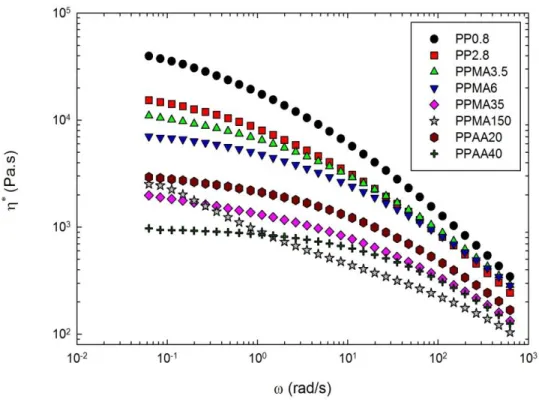
Figure 5-1: Complex viscosity as a function of angular frequency for the neat polymers; T = 190ºC. ... 55 Figure 5-2: ATR FTIR spectra of the neat polymers; (a) maleic anhydride and acrylic acid
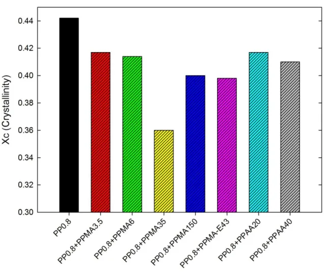
groups, (b) ethylene groups. ... 57 Figure 5-3: DSC thermograms of the neat polymers: (a) second heating and (b) cooling. ... 58 Figure 5-4: Crystallinity of the precursor films of PP0.8 and its blends with different modifiers
(2wt%). ... 59 Figure 5-5: (a) Crystalline and (b) amorphous orientation parameters (obtained from FTIR) of
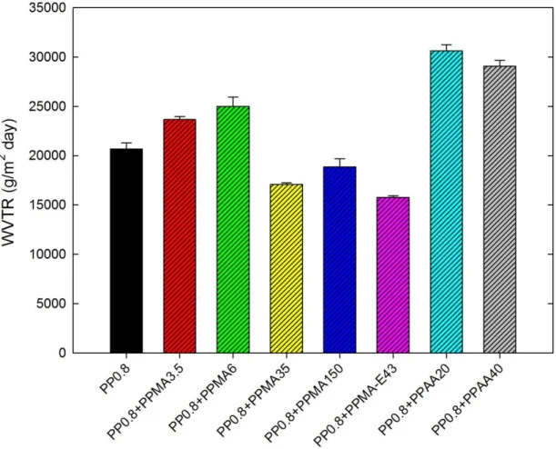
precursor films of PP0.8 and its blends with different modifiers (2wt%). Annealing was performed at 120 °C for 30 min. ... 60 Figure 5-6: Water vapor transmission rate of the PP0.8 blends with different modifiers (2wt%). 62 Figure 5-7: Crystalline orientation parameter (obtained from FTIR) and melting enthalpy
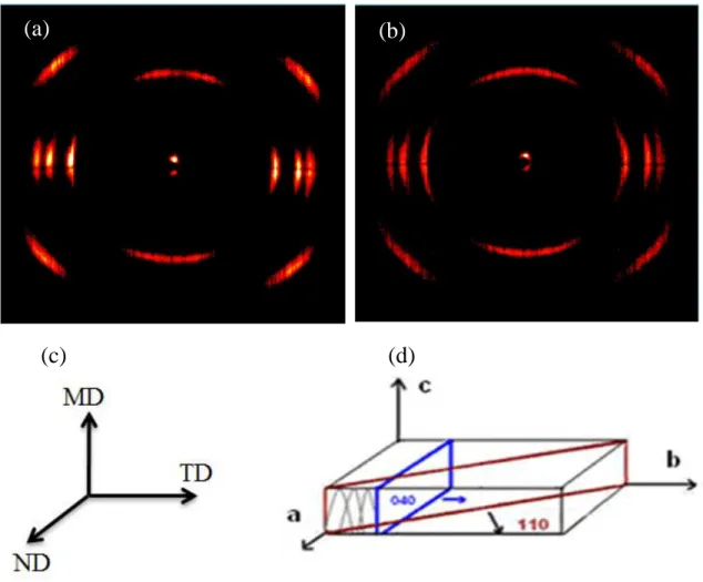
(obtained from DSC) as a function of PPMA6 and or PPAA20 content (wt%) in (a) & (b) PP0.8 matrix, and (c) & (d) PP2.8 matrix. ... 64 Figure 5-8: WAXD patterns of the precursor films. (a) PP0.8, (b) PP2.8, (c, d) film production
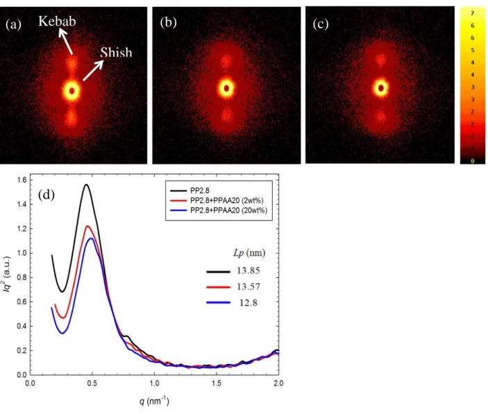
axes and crystal block coordinates, respectively. ... 65 Figure 5-9: SAXS patterns of precursor films, (a) PP2.8, (b) PP2.8+PPAA20 (2wt%), (c)
PP2.8+PPAA20 (20wt%) and (d) SAXS intensity profiles for precursor films for the neat PP2.8 and blends with PPAA20. ... 66 Figure 5-10: Water vapor transmission rate as a function of PPMA6 or PPAA20 content (wt%) in
(a) PP0.8 and (b) PP2.8. ... 69 Figure 5-11: Surface O/(C+O)% for PP2.8 films modified using PPAA20 with different additive
concentrations determined using XPS. ... 70 Figure 5-12: SEM micrographs of the surface of the microporous membranes, (a) PP2.8, (b)
PP2.8+PPAA20 (2wt%) and (c) PP2.8+PPAA20 (20wt%); (the arrows indicate the stretching machine direction). ... 71 Figure 5-13: (a) Elongation at break and (b) Young modulus as functions of PPMA6 or PPAA20
Figure 5-14: Normalized maximum force for piercing in PP0.8 based precursor films and membranes as function of PPMA6 content (wt%). ... 74 Figure 6-1: ATR-FTIR spectra of the neat materials and the precursor films of the blend sample
before and after immersion in theTiO2 nanoparticle suspension. ... 91
Figure 6-2: High-resolution XPS spectra of (a) the Ti2p peaks of the TiO2 powder, (b) the O1s peaks of the TiO2 powder, (c) the C1s peaks of the blend sample and (c) the O1s peaks of the blend sample. ... 93 Figure 6-3: Water contact angles of the blend sample (precursor films of PP+PP-g-AA (2wt%))
before and after immersion in TiO2 suspension; The insets exhibit images of the water droplets. ... 95 Figure 6-4: TGA curves of the blend sample (microporous membrane of PP+PP-g-AA (2wt%))
before and after immersion in the TiO2 suspension under an air atmosphere. ... 96 Figure 6-5: Water vapor transmission rate (WVTR) of the neat PP and blend microporous
membranes, before and after immersion in TiO2 suspension. ... 98 Figure 6-6: EDS spectra of (a) the blend precursor film and microporous membrane, after
immersion in the TiO2 suspension and (b) TiO2 powder. ... 99 Figure 6-7: SEM micrographs of the surface of the blend microporous membranes, (a) before and
(b) after immersion in the TiO2 suspension; (the arrows indicate the stretching machine direction). ... 100 Figure 7-1: SAXS patterns of precursor films, (a) non-annealed, (b) annealed at 80 °C, (c)
annealed at 120 °C, (d) annealed at 140 °C and (e) SAXS intensity profiles and (f) SAXS correlation functions for non-annealed and annealed samples at different annealing temperatures (t=30 min). ... 118 Figure 7-2: Schematic representation for the (a) non-annealed and (b) annealed crystal
morphologies at 140 °C based on the SAXS correlation function results. ... 119 Figure 7-3: DSC thermograms of the annealed films at different annealing temperature
Figure 7-4: (a) Tear resistance along MD and (b) crystalline orientation parameter (obtained from FTIR) and crystallinity (obtained from DSC), as functions of the annealing temperature (t=30min). ... 123 Figure 7-5: (a) Stress–strain curves along MD of the annealed films at different annealing
temperature; strain rate = 50mm/min and (b) normalized maximum force for piercing as a function of the annealing temperature (t=30min); strain rate = 25mm/min. ... 126 Figure 7-6: SAXS patterns of precursor films, (a) non-annealed, (b) annealed for 5 min, (c)
annealed for 10 min, (d) annealed for 30 min and (e) SAXS intensity profiles and (f) SAXS correlation functions for non-annealed and annealed samples at different annealing times (T=120 °C). ... 127 Figure 7-7: DSC thermograms of the annealed films at different annealing times (T=120 °C); (the
inset shows details of the lower temperature range of the plot). ... 128 Figure 7-8: (a) Crystalline orientation parameter (obtained from FTIR) and crystallinity (obtained
from DSC) and (b) tear resistance along MD as functions of the annealing time (T=120 °C). ... 129 Figure 7-9: (a) Stress–strain curves along MD of the annealed films at different annealing time;
strain rate = 50 mm/min and (b) normalized maximum force for piercing as functions of annealing time (T=120 °C); strain rate = 25 mm/min. ... 130 Figure 7-10: Relationship between the second yield stress of the tested samples and the relative
lamellae thickness (lc- lc*). ... 132 Figure 7-11: DSC of the final membranes prepared from the non-annealed and annealed samples. ... 133 Figure 7-12: SEM micrographs of the surface of the microporous membranes for different
annealing conditions, (a) 120 °C- 5 min, (b) 120 °C- 30 min, (c) 130 °C- 30 min; (the arrows indicate the stretching machine direction). ... 135 Figure 7-13: Water vapor transmission rate as a function of (a) annealing time (T= 120 °C) and
Figure 8-1: (a) WAXD patterns and (b) SAXS patterns of the PP precursor films, the schematic on the left represents the film production axes and crystal block coordinates. ... 150 Figure 8-2: Stress–strain curves along MD of the annealed precursor films at different strain
rates. ... 152 Figure 8-3: SEM micrographs of the cross-section of the precursor films after cold stretching
only up to 35% of their initial length at (a) strain rate = 5 mm/min and (b) strain rate = 200 mm/min, (the arrows indicate the stretching machine direction). ... 153 Figure 8-4: Water vapor transmission rate as a function of strain rate for the precursor films after
cold stretching only up to 35% of their initial length and microporous membranes obtained from cold stretching of 35% followed by hot stretching of 60%. ... 154 Figure 8-5: SEM micrographs of the surface (left images) and cross-section (right images) of the
microporous membranes prepared at (a) strain rate = 5 mm/min and (b) strain rate = 200 mm/min; cold stretching of 35% followed by hot stretching of 60%, (the arrows indicate the stretching machine direction). ... 156 Figure 8-6: Water vapor transmission rate as a function of cold stretch ratio, hot stretching of
60% and strain rate = 50 mm/min. ... 158 Figure 8-7: SEM micrographs of the surface of the microporous membranes as a function of cold
stretch ratio, (a) 0%, (b) 15%, (c) 35%, (d) 50%, (e) 100%, (f) 250%; hot stretching of 60% and strain rate = 50 mm/min, (the arrows indicate the stretching machine direction). ... 159 Figure 8-8: (a) SEM micrographs of the cross-section of the precursor film after hot stretching
only (60%), (the arrows indicate the stretching machine direction), and (b) pore size distribution via MIP for the membranes obtained using two different stretching conditions; (the legend shows the porosity values), strain rate = 50 mm/min. ... 160 Figure 8-9: SEM micrographs of the surface of the microporous membranes as a function of hot
stretch ratio at 120 °C, (a) 30%, (b) 60%, (c) 100%; cold stretching of 35% and strain rate = 50 mm/min, (the arrows indicate the stretching machine direction). ... 162 Figure 8-10: (a) Water vapor transmission rate and (b) DSC thermograms of the membranes
prepared under different hot stretch ratios at 120 °C; cold stretching of 35% and strain rate = 50mm/min. ... 162
Figure 8-11: Water vapor transmission rate as a function of hot stretching temperature; cold stretch ratio of 35% followed by hot stretch ratio of 60% and strain rate = 50mm/min. ... 163 Figure 8-12: SEM micrographs of the surface of the microporous membranes as a function of hot
stretching temperatures, (a) 100 °C, (b) 120 °C, (c) 140 °C; cold stretch ratio of 35% followed by hot stretch ratio of 60% and strain rate = 50mm/min, (the arrows indicate the stretching machine direction). ... 164
CHAPTER 1 INTRODUCTION
Microporous membranes are commonly used in separation processes such as filtration, battery separators and medical applications to control the permeation rate of chemical components. Due to the wide range of chemical structures, optimum physical properties and low cost of polymers, these materials are known as the best candidates for the fabrication of microporous membranes. Three commercially available processes are used for making microporous membranes: solution casting followed by phase separation (also known as extraction process), particle stretching, and dry-stretching. In the phase separation process, the polymeric raw material is mixed with processing oil or plasticizer and this mixture is extruded, then, the plasticizer is removed by extraction (Gozdz et al. 1997). In the particle stretching process, the polymeric material is mixed with solid particles, this mixture is extruded, and pores are formed during stretching at the interface between the polymer and solid particles (Aoyama et al. 1990). Processing cost, pore size control and solvent or particle contaminations are the main drawbacks of the solution and particle stretching techniques. The process to develop membranes by stretching, without using a solvent or extra component, has been introduced since 30 years ago for some semi-crystalline polymers.The dry-stretch process, which is the method used in this study, is based on stretching of a polymer film containing a row-nucleated lamellar structure. This method is relatively less expensive in comparison to the other methods and there is no solvent contamination. The major disadvantage of this method is low tear resistance of the final membranes in the stretching direction.
Three consecutive stages are carried out to obtain porous membranes by this technique: (1) creating a precursor film containing the desired lamellar morphology, i.e., an oriented shish-kebab structure, through shear and elongation-induced crystallization of the polymer having
proper molecular weight and molecular weight distribution, (2) annealing the precursor film at elevated temperatures to improve the crystalline structure, and (3) stretching at room temperature to create the pores by lamellar separation and then, stretching at a high temperature to enlarge them (Sadeghi 2006; Tabatabaei 2009; Liu et al. 2013). To produce microporous membranes by the stretching technique, obtaining precursor films with an adequate orientation and alignment of the crystal lamellae are needed (Sadeghi 2006; Tabatabaei 2009). The type of resin and applied processing conditions are the key factors for the production of the precursor films with controlled type, orientation, and connection of the crystals, which in turn control the final membrane structure.
Semi-crystalline polypropylene (isotactic PP) is one of the most commonly used polymers today in a variety of applications due to its outstanding properties, such as low cost, easy processing, good mechanical properties, chemical stability and non-toxicity (Xu et al. 2010). Despite its popularity as a membrane material, PP does not adhere to many substances such as water or to hydrophilic substrates because of its intrinsic hydrophobic nature. This limits its applications in wastewater treatment, desalination of sea water, electrode separators in batteries and biomedical applications (Bongiovanni et al. 1998; Hester et al. 1999; Fang et al. 2009; Xu et al. 2010). Hydrophobic membranes are also prone to fouling when used in treating aqueous solutions containing natural organic matter, e.g., oil droplets or macromolecular species. Organic matter is easily adsorbed onto the membrane surface or pore walls and results in the deterioration of the membrane performance. Subsequently, replacement and maintenance costs of membrane modules are increased (Hester et al. 1999; Fang et al. 2009; Li et al. 2009). Membrane fouling can be divided into reversible and irreversible fouling. Reversible fouling caused by reversible organic matter adsorption, which occurs in a hydrophilic surface, can be fully or partly removed.
Irreversible fouling is caused by irreversible organic matter adsorption on the hydrophobic surface and can only be eliminated by chemical or biochemical cleaning (Meier-Haack et al. 2004; Zhang et al. 2010). The cause for irreversible fouling is the lack of hydrogen bonding interactions between the hydrophobic membrane and water in the boundary layer, which leads to the spontaneous process of the repulsion of water molecules away from the surface. By contrast, membranes with a hydrophilic surface are able to form hydrogen bonds with the surrounding water molecules (Li et al. 2013). It is difficult for hydrophobic solutes to approach the water boundary and break the orderly structure due to the energy required to remove the water boundary and expose the membrane surface (Meier-Haack et al. 2004; Zhang et al. 2010). Furthermore, the presence of a spontaneous and permanent wettable surface is a basic requirement for a battery separators to accommodate the aqueous electrolyte solution and prevent solvent leakage, which often causes the deterioration and reduces the life of a battery (Goel et al. 2009; Kim et al. 2010). Accordingly, increasing the hydrophilicity of the membrane surface is the general approach used to prevent irreversible membrane fouling and, as well, to improve the surface properties, such as adhesion and printability (Bongiovanni et al. 1998; Zhang et al. 2010). Despite this drawback, hydrophobic materials have higher mechanical and chemical stability than hydrophilic materials, which are used in membrane applications (Hester et al. 1999; Meier-Haack et al. 2004). Thus, the ideal membrane would combine the superior bulk properties of hydrophobic materials with the surface chemistry of hydrophilic materials (Hester et al. 1999; Datla 2008).
Different strategies have been carried out to improve hydrophilicity of the membrane surface, i.e., increasing the amount of surface polar groups and maximizing hydration. However, blending of
polymers is by far one of the most efficient techniques to generate new materials with desired properties while satisfying the economic aspects (Datla 2008).
The main motivation of this study is improving hydrophilic properties of microporous polypropylene membranes through cast extrusion. To achieve this goal, in the first phase of this study, different commercial amphiphilic modifiers, i.e., maleic anhydride and acrylic acid grafted polypropylene (PP-g-MA and PP-g-AA), were melt blended at different concentrations with PP to examine the hydrophilicity and crystalline structure of the PP based microporous membranes. In the next step, the hydrophilic properties of the microporous membranes are enhanced through grafting TiO2 with COOH groups on the surface. Having obtained an understanding of the
membrane process, the last phase of the thesis looks in depth at the influence of annealing and stretching conditions on the crystalline structure and membrane performance. Understanding these mechanisms is important to prepare membranes with the desired performances.
This dissertation is based on four articles that have been published or submitted to scientific journals, and consists of the following chapters:
Chapter 2 provides a literature review considering the related issues.
The objectives are introduced in Chapter 3.
In Chapter 4, the organization of the articles is described.
Chapters 5-8 include the four articles describing the main results obtained in this study.
Finally, Chapter 10 summarizes the most important conclusions of this thesis and outlines some recommendations for the future works in this area.
CHAPTER 2 LITERATURE REVIEW
2.1 Polypropylene structure
Polypropylene was discovered in the early 1950s by Giulio Natta. It is prepared by polymerizing propylene in the presence of a catalyst under carefully controlled heat and pressure. Propylene as a gaseous by-product of petroleum refining is an unsaturated hydrocarbon, containing only carbon and hydrogen atoms. Depending on the catalyst and the polymerization method used, the molecular configuration can be altered to produce three types of polypropylenes: atactic, isotactic, and syndiotactic configurations. The Ziegler-Natta catalyst, which was developed in the 1950s, makes the isotactic formation possible with a high level of crystallinity and different molecular weights (Datla 2008). Isotactic polypropylene (iPP) is one of the most commonly used polymers today in many different applications due to its outstanding properties, such as low cost, easy processing, good mechanical properties, chemical stability and non-toxicity (Van der Meer 2003; Xu et al. 2010). Nowadays, the commercially available polypropylene grades usually show a very high fraction of isotacticity; therefore, the term "PP" refers to isotactic polypropylene in the following discussion.
The crystal forms of PP are quite complicated and highly dependent on the processing conditions. PP possesses four crystal forms: α, β, γ, and smectic forms. All of these forms involve the same 31-helix conformation as shown in Figure 2-1, but packed differently when folded into lamellae
Figure 2-1: (a) Isotactic Polypropylene, (b) The 31-helix, (c) The 3i -helix with only showing
methyl groups (Lin 2008).
The α-phase: The most common crystalline form encountered in conventional processing conditions, such as under a slow cooling and high stress, is the α-form (Lin 2008). The monoclinic unit cell of α form has the following parameters a = 6.65Å, b = 20.96Å, c = 6.5Å and β=99.62°. The overall density is 0.946 g/ cm3
and melt at about 160 oC (Van der Meer 2003). The β-phase: The β-form can be found in some specific processing conditions such as large temperature gradient or fast cooling or use of nucleating agents (Van der Meer 2003). The β-form is thermally unstable with a melting temperature of 152 °C, and can transβ-form to the α-β-form at elevated temperature or under stress (Lin 2008). The β phase has a trigonal unit-cell with lattice parameters a = b = 11.0 Å, c = 6.5Å, β = 120° and density = 0.922 g/cm3.
The γ-phase: The γ crystal structure is tetragonal (a=6.38 A , c = 6.33 A , N =1, density = 0.939 g/cm3) and may be formed in low molecular weight PPs or when crystallization is performed under high pressure. In this unit cell the c-axis is not parallel with chain axis direction and have an angle of + or - 40° with the normal direction of the lamellae (Van der Meer 2003; Lin 2008). Smectic form: The smectic form presents a state of order intermediate between amorphous and crystalline states (a transition crystallographic state). This form found under very rapid cooling and transforms into the α-form at elevated temperatures (Lin 2008). The smectic-to-α form transition can be characterized with an apparent exotherm peak at a temperature from 65 to 120 °C (Lin 2008).
2.2 Crystallization process
When a semi-crystalline polymer crystallizes, the polymer chains tend to pack and form a crystalline layer called lamellae. The thickness of the lamella varies from approximately 4 nm for the crosshatched lamellae to several tens of nanometers for primary grown lamellae. Since the typical polymer chain length is about 1000 nm, the only explanation for the conformation of the polymer chains in the lamellar structure is chain folding (Lin 2008). Lateral dimensions of the lamellae may reach several micrometers. The lamellae are separated by amorphous layers while its thickness is usually in the order of the thickness of lamellae (Van der Meer 2003).
It is known that strain can accelerate the crystallization kinetics of the polymer, increase the nucleation rate and change the crystalline morphology. Therefore, the crystallization of polymers can be divided into the following regimes:
2.2.1 Quiescent crystallization: Spherulites
In an unstressed state, crystallization usually starts at some kind of isolated and discontinuous nuclei and lamellae grow radially along the growth direction and form the spherulitic morphology (see Figure 2-2a). Spherulites do not have the oriented regularity on a lamellar scale along the extrusion direction (Zhou 1997; Van der Meer 2003).
2.2.2 Flow induced crystallization (FIC)
Flow-induced oriented molecular chains markedly increase the nucleation rate and the crystal growth rate of the polymer and form a different morphology with respect to quiescent conditions (Lamberti 2011). Basically, a polymer can be under the influence of an elongational flow (stretching flow) or a shear flow, even though in most processing operations both elongational and shear fields are applied on melts (Steenbakkers 2009). Compared to shear flow, the elongational flow is much more effective in inducing chain extension and orientation. A major consequence of chain extension is the decrease in conformational entropy and a corresponding increase in the free energy. This means an increase in the driving force for crystallization at a fixed processing temperature (Zhou et al. 2010). Also, we can consider that a simple shear flow may be represented as the superposition of a purely elongational flow and a purely rotational flow. The rotational and elongational components in a simple shear flow are equal, such that the polymer cannot attain a stable fully stretched condition: the extensional component orients and stretches the molecules, whereas the rotational component causes a fluctuation in the extension (Iervolino 2006). Therefore, shear flow is considered a weak flow that is less efficient than elongational flow in obtaining orientation or stretching. Although numerous studies have been conducted on the effect of shear flow on the crystallization of various resins, very little has been
reported on the role of elongational flow. This lack of investigations is due to the difficulties to measure the extensional material functions. For instance, it is still impossible to reach very large strains and deformation rates with the existing elongational rheometers. Elongational flow can be created in many devices and geometries including two roll and four roll mills, converging flow and cross-slot device.
Under elongational flow, certain polymer chains are extended; therefore, thermodynamically as well as kinetically, these portions of the chains can crystallize faster and form row-nucleated fibril crystals. The first-formed row-nucleated fibril crystals can then serve as nuclei for the later development of chain-folding lamellar crystals (Zhou 1997). Combination of the above two structures is commonly refereed as shish-kebab or row morphology (see Figure 2-2b).
(a) (b)
Figure 2-2 : Schematic of a) a spherulitic and b) a shish-kebab structure (Bashir et al. 1986).
The flow induced crystallization process to produce shish kebab structure can be summarized as follows:
Initially, the molecular chains of polymers are presented as random coils in the melt (Figure 2-3a). After applying a steady deformation, the chains are stretched slightly (Figure 2-3b), which aggregates each one to form a bundle structure and promotes the formation of stable nuclei.
These stable nuclei align tightly in the direction of flow to form the fibrillar-like skeleton structure (oriented crystal nuclei) (Figure 2-3c). Subsequently, these aligned nuclei grow by absorbing the neighboring molecular chains. The nuclei grow perpendicularly to the direction of flow, which leads to the 2-dimensional growth of polymer crystals (Figures 2-3d and e). The final result is the shish–kebab crystal structure: the oriented nuclei aggregate tightly and form the shish-like fibrillar crystal skeleton, while the lamellae grow epitaxially around it (Zhang et al. 2008).
Figure 2-3: Schematic picture of flow-induced crystallization: (a) amorphous molecular chains in melt, (b) flow-induced molecular chain orientation, (c) formation of oriented crystal nuclei, and (d and e) 2-dimensional growth of crystal (Zhang et al. 2008).
According to the mechanism of flow-induced crystallization of polymer melts, if the linear row nuclei or shish did not form, the subsequent growth of kebabs, i.e., lamellae perpendicular to the flow direction would not be possible. The processing parameters as well as resin characteristics
(e.g. molecular weight, molecular weight distribution and long chain branching) are the key factors for controlling the morphological features of the extruded precursor films (Sadeghi 2006; Tabatabaei 2009). Also, die temperature, die gap, rate and position of the air cooling unit, chill roll temperature, and draw ratio are the major processing parameters that need to be optimized depending on the resin.
The crystalline morphology of films is dependent on the stretch ratio. If the deformation applied in a flow is strong enough, highly oriented structures can be observed. This factor is controlled by the melt and stretch speeds. The ratio of stretch speed to the melt velocity determines the value of draw ratio (DR). Lower DRs result in fully spherulitic structures. By increasing DR, the radius of the spherulite decreases and the spherulite gradually becomes smaller and deforms. With a further increase in DR, the polymer melt stretchs faster so that severely deformed spherulites are now dominant and develop a fiber-like structure. The rate of increase of the orientation is relatively high with an increase of DR. When the DR becomes even larger, spherulites are difficult to form and most chains are oriented and later introduced into the shish structures. As a result, the shish (or shish kebab) structure becomes dominant (see Figure 2-4) (Zhou et al. 2010).
Figure 2-4: Model interpretation of the morphology evolution with the increase of DR (Zhou et al. 2010).
Tabatabaei (2009) and Sadeghi (2006) also observed that the draw ratio in polypropylene cast films improved the orientation along the machine direction. They reported a linear relationship between the orientation function and draw ratio. Also, they showed that at low draw ratios the lamellae are not well aligned perpendicularly to the flow direction, but as DR increases, the lamellae align themselves perpendicularly to the machine direction (MD).
As mentioned above, the process for the formation of such a lamellar structure is based on the elongation of the chains in the melt state followed by a rapid crystallization. It is obvious that the chains should preserve their elongated form to be able to act as initial nuclei. The relaxation time of the chain is also the other important factor for this stage. Based on experimental evidence, a critical deformation or elongation rate needs to be exceeded to change from the spherulitic to the oriented crystallization regime where fibrillar growth occurs (Bischoff White et al. 2012; Custodio et al. 2009; Steenbakkers 2009). In the absence of flow, the elongated chains will relax to random coils. So, there is a competition between these two factors, i.e., deformation and relaxation. If the length of an elongated chain is larger than the size of a critical bundle nucleus, it is possible for nucleation to progress. On the other hand, nucleation cannot progress. This is the reason why critical deformation exists for the formation of shish. It is to be noted here that critical deformation may depend on the characteristics of the polymer, and decreases with the addition of long chains which has the largest relaxation time (Yamazaki et al. 2005).
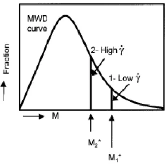
Somani et al. (2000) followed the orientation development upon applying different shear rates. They found that the deformation rate must be high enough to orient and align the polymer chains in the melt to form stable nuclei in the flow direction. At a given shear rate, only those molecules having a chain length (molecular weight) above a critical value can form stable oriented row nuclei, while the rest of the molecules will remain un-stretched. Then the result would be a
bimodal distribution of chain molecules represented by a dual population of oriented and non-oriented chains. Their findings showed that increasing shear rate did not enhance the chain extension, but increased the amount of chains that became oriented. Then a structure with a bimodal population of oriented and non-oriented chains was created as can be seen in Figure 2-5. This figure shows that the “critical molecular weight” (M*) on the curve shifts to a higher values at low deformation rates, as showed by the lines (1- low shear rate and 2- high shear rate). The area under the MWD curve represents the fraction of material above or below the critical molecular weight. It was claimed that the value of M* is more sensitive at low shear rates than at higher ones, reaching a plateau at high shear rates (Somani et al. 2000).
Figure 2-5: Schematic showing the effect of imposed shear conditions on the shift in the location of the critical molecular weight M* (Somani et al. 2000).
Nogales et al. (2001) proposed a method to calculate the critical molecular weight for orientation. They considered the oriented structure based on the change in the radius of gyration and the
degree of chain extension is represented as the ratio of the radius of gyration of the extended chain to that of non-oriented chain. The comparison between the radius of gyration in direction parallel to the deformation field and the radius of gyration in the perpendicular direction to the deformation field can represent finally the orientation.
Under isothermal conditions, the molecular weight and chain architecture are expected to play major roles in governing the extent of elongation and stability of the oriented structures after cessation of shear. Longer chains and branched molecules both take a longer time to relax after deformation than shorter ones, and thus, have a better chance of being oriented. The longer chains from the high molecular weight tail would give rise to orientation-induced nuclei due to higher orientation compared to the shorter chains. The short chain molecules relax in a very short time after deformation and hence cannot form nuclei under flow. But, it has been shown that temperature dependency of the relaxation time is much stronger than that of the zero shear viscosity (Somani et al. 2000).
The die temperature (the extrudate temperature) affects the relaxation of the molecules. Low temperature will slow down the chain relaxation, leading to an increase probability for the formation of lamellae by the low molecular weight chains. However, very low extrusion temperatures prevent the mobility of the molecules, which results in a non-appropriate row-nucleated lamellar structure. Therefore, an optimum temperature needs to be selected for each polymer. Tabatabaei (2009) reported that the overall effect of moving towards lower temperature is more deteriorating than processing at higher temperature. Their results showed that the use of air cooling in addition to chill rolls helps flow induced crystallization to occur at lower temperatures for PP and HDPE monolayer films as well as in multilayer films (PP/HDPE/PP). The use of air cooling in addition to chill rolls noticeably increased the number of shish or nuclei
sites, and consequently the crystallization kinetic is promoted, resulting in a well oriented shish-kebab structure. This was due to preserving the oriented states for the chains; otherwise, chains relax after stretching due to their tendency to return to their initial coil state.
Sadeghi (2006) and Tabatabaei (2009) considered the influence of molecular weight and long chain branched PP on orientation of row-nucleated lamellar structure using WAXD, SAXS and FTIR. They found that molecular weight was the main resin factor that controlled the PP crystal structure. It was demonstrated that the resin with high molecular weight developed larger orientation and thicker lamellae than the resin with low molecular weight. Sadeghi (2006) realized that an initial orientation was required in order to obtain a lamellar structure. The crystalline orientation in the precursor film depended on the molecular weight of the resin and the type of film process (i.e. cast film or film blowing). It was shown that the cast film process was more efficient than film blowing for producing precursor films with the appropriate crystalline orientation. Sadeghi (2006) compared the structure and properties of the precursor films obtained from a linear PP and its blend with 2 wt% long chain branched PP (LCB-PP). The addition of a small amount of a branched component drastically affected the row-nucleated crystalline structure of the precursor film. Blending improved the orientation of both the crystalline and amorphous phases and led to the formation of much more lamellae than in the neat linear resin. Tabatabaei (2009) also reported that adding high molecular weight enhanced the orientation of both the crystalline and amorphous phases.
Somani et al. (2006) compared the oriented microstructure in isotactic polypropylene melts (PP-A and PP-B) with the same number average molecular weight but different molecular weight distribution (MWD) under shear flow. The amount of the high molecular weight species was larger in PP-B than in PP-A. Both samples were subjected to identical same shear conditions.
Their results elucidated that the shish structure formed much earlier for PP-B with a more pronounced crystal orientation and a faster crystallization kinetics. They concluded that even a small increase in the concentration of the high molecular weight chains led to a significant increase in the shish or nuclei sites formation. Seki et al. (2002) prepared a very high molecular weight polypropylene (Mw= 923.2 (kg/mol)), through the fractionation of a regular PP, and blended it with a moderate molecular weight PP. Using this approach, they showed that the addition of less than one percent of this polypropylene to a typical iPP with moderate molecular weight (Mw=186 kg/mol) significantly influenced the crystallization kinetics and resulted in a lamellar morphology.
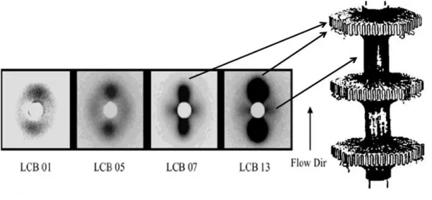
Also, Agarwal et al. (2003) studied the shear induced crystallization in chain branched polypropylene. They investigated several polypropylenes with different branching index while their number-average molecular weights were relatively constant. But, the high molecular weight components (Mw, Mz and Mz+1) increased with the branching level. Thus, the highly branched
species resided at the high molecular weight species of the molecular weight distribution. They studied the SAXS pattern for shear induced crystallization of a branched polypropylene and observed that equatorial and meridian maxima appeared when shear was applied to the melt. They attributed the equatorial peaks to fibrils and meridians to lamellae and also revealed that the intensity of the patterns was enhanced with increased branching (see Figure 2-6). The crystal orientation was stronger for the branched polypropylene in comparison to linear PPs. A larger crystallization rate for the branched PP was also reported in comparison to linear PPs. The higher crystallization rate in branched PPs is likely due to greater nucleation rate as a result of chain orientation.
Figure 2-6: Comparison of 2D SAXS patterns of the four LCB-iPPs,: shear rate= 60s-1,
ts(shearing time) 0.25 s, T= 140 °C (Agarwal et al. 2003).
2.3 Overview of the membrane technology
2.3.1 Membrane classification
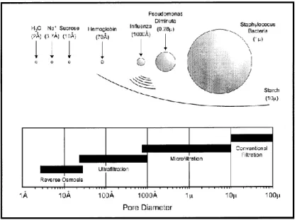
Membrane can be used as a semi-permeable barrier in order to separate particles dissolved in a fluid or components of a solution due to their chemical or physical properties when a driving force is applied (Chandavasu 2001). Polymers and polymer blends are among the best candidates for the development of the membranes due to their properties such as wide range of chemical structures, optimum physical properties and low cost. Polymeric membranes have been developed for various industrial applications such as microfiltration, ultrafiltration, reverse osmosis (RO), gas separation, and wastewater treatment (Baker 2004). Membranes are commonly classified based on the size of the separated materials as depicted in Figure 2-7.
Figure 2-7: Separation processes differing in the size of the particles to be separated (Baker 2004).
Depending on the structure, polymeric membranes are divided in two categories: isotropic membranes and anisotropic membranes. Isotropic membranes contain uniform structure while anisotropic membranes have a chemically or a physically heterogeneous structure.
Isotropic membranes can also be classified in three categories as follows (Baker 2004):
Microporous membranes: this kind of membranes has a highly porous structure with randomly distributed interconnected pores. In microporous membranes, pores size varies from 0.01 to 10 μm in diameter.
Nonporous or dense membranes: this is a dense film in which permeates penetrates by diffusion under an applied driving force of a pressure, concentration, electrical potential gradient (or a combination of two or three).
Electrically charged membranes: in this type of membranes, the separation is obtained by the exclusion of the particles with same charge.
On the other hand, anisotropic membranes have a skin/core structure. The skin layer is an extremely thin surface layer supported on a much thicker core with porous structure. The skin/core structure can be formed in a single operation or separately. A schematic diagram of isotropic and anisotropic membranes is illustrated in Figure 2-8.
Figure 2-8: Schematic diagrams of the various polymeric membranes (Dang 2009).
2.3.2 Membrane fabrication techniques
Polymeric membranes are made through various techniques such as: phase separation, track etching, leaching, thermal precipitation, and stretching.
Phase inversion can be described as a de-mixing process whereby the initially homogeneous polymer solution is transformed in a controlled manner from a liquid to a solid state. This transformation can be accomplished in several ways, namely (a) thermally induced phase separation (TIPS); (b) controlled evaporation of solvent from three component systems; (c) precipitation from the vapour phase and (d) immersion precipitation (IP) (Liu et al. 2011). One of the main difficulties that limits the successful casting of phase inversion membranes is the lack of a predictable and systematic method in selecting solvent systems (Liu et al. 2011). The TIPS process can be applied to semi-crystalline polymers with suitable diluents; however, it is a less attractive process due to large pore sizes and the necessary post-treatments for solvents (Lin 2008).
In the track etching method, polymer films or foils are subjected to high energy particle radiation (metal ions) applied perpendicularly to the material, followed by etching in acid or an alkaline bath. Consequently, cylindrically shaped pores with uniform pore size distributions, symmetric porous structures, could be obtained. While the membrane porosity is mainly determined by the duration of radiation, the pore size is determined by the etching time and temperature (Liu et al. 2011). The membrane becomes very brittle as porosity increases. The pore size is also limited and cannot be smaller than 0.01 µm (Lin 2008). Leaching is based on extrusion of the polymeric raw material added with solid particles followed by the extraction of the solid, leading to pores formation. In thermal precipitation, cooling of a mixture of a solvent and polymer is applied to enable phase separation followed by extraction of the solvent. Stretching technique is based on the stretching of a polymer film containing a dispersed phase where upon stretching pores are created due to stress concentration at the interface of these sites (Baker 2004), or stretching a specific crystalline morphology as detailed below. In this method, a porous membrane is developed without the use of any solvent (Lin 2008).
Stretching technique:
This technique is based on the drawing of a polymer film or sheet having one of the followings: filler particles (Nagō et al. 1992), droplets of an immiscible polymer component (Xanthos et al. 2002), a mixed solvent (Williams et al. 1974), beta or hexagonal unit cell crystals (Shi et al. 1989), or a stacked lamellar structure. Since the aim of this dissertation is making microporous membranes by stretching a stacked lamellar crystalline structure, introducing other stretching techniques will help the reader in understanding the importance of the process used.In the stretching of a filler polymer film, the resin is first mixed with a filler and then melt extruded to prepare a composite film or sheet. Upon applying stretching, cracks are initiated and, subsequently, propagated at the interface of filler particles and polymer matrix. The filler can be a mineral or organic compound. The pore size, pore size distribution and porosity depend on the type of filler, its interaction with the polymer matrix, blending process, amount of filler and also film thickness. To completely remove the filler from the polymer matrix after drawing, the filler should have poor wetting ability with the polymer matrix (Yu 1995). The most important stage is the filler incorporation, which includes dispersion and distribution of the filler throughout of the matrix.
Different inorganic fillers can be used; among them, calcium carbonate and barium sulfate are particularly preferred (Aoyama et al. 1990). The important issues are the shape of the particle, the price, the whiteness, the interaction with the matrix and the availability. The average particle size of inorganic fillers according to ASTM C-721-76 should be 0.4 to 4m or smaller. Using filler larger than that might limit the stretchability and create a non-uniform pore distribution and, in some cases, breakdown might occur. The amount of inorganic filler to be added should be sufficient to attain the desired porosity, but it depends to some extend on the kind and particle
size of the inorganic filler. Inorganic fillers such as calcium carbonate are preferably surface treated to be hydrophobic so that the filler can repel water to reduce agglomeration of the filler. For calcium carbonate, a preferred coating is calcium stearate or steraric acid (Kundu et al. 2003). Xanthos et al. (2002) were probably the first investigators to develop microporous membranes based on stretching of immiscible polymer blends. In that study, stretching caused debonding at the interface of incompatible polymer blends of PP and PS and also a small amount of a copolymer as a compatibilizer, resulting in membrane formation. Their findings showed that the dispersion of the minor component with a narrow particle size distribution was the most important factor controlling the pores size.
The solvent stretching technique was invented by Williams et al. (1974). In this technique, a polymeric film having at least two components is immersed in a solvent and absorption of the solvent takes place in the component with lower volume fraction. Then, the film is first stretched in one or two directions while it is in contact with the solvent and then maintained in its stretched form during the removal of the solvent. The membrane development based on crystal transformation method is utilized for polymers that have different types of crystal phase, which can be transformed under specific conditions. The most common polymer of this kind is polypropylene. As mentioned before, the β crystalline form is not stable and under certain levels of stress transforms into the more stable α crystalline form. Shi et al. (1989) revealed that the β crystals transformed into a smectic state at a drawing temperature below 80 ºC, but transformed to the more stable α form at higher temperatures. Since the β crystals are less dense than α, this transformation caused volume contraction in the bulk of polymer, resulting in the creation of voids.
Costly processes and difficulties in dealing with solvent or particle contaminations as well as the presence of the nucleating agents are the main drawbacks of the methods described above.
However, besides the above stretching methods, uniaxial stretching of a stacked lamellar structure has been developed for fabricating microporous membranes. Three consecutive stages are carried out to obtain porous membranes by this technique: (1) creating a precursor film containing the desired lamellar morphology, i.e., an oriented shish-kebab structure by mechanism of shear and elongation-induced crystallization, (2) annealing the precursor film at elevated temperatures to improve the crystalline structure, and (3) stretching at low and high temperatures to create and enlarge pores, respectively, in the machine direction (MD) to create the pores by lamellae separation (Sadeghi 2006; Tabatabaei 2009) (see Figure 2-9). For instance, Figure 2-10 illustrates the structure of a PP film before and after stretching. Obviously, a large number of interconnected micro-voids are produced upon uniaxial deformation of the annealed film.
Figure 2-10: SEM micrographs of surface of a PP film a) before and b) after stretching (Tabatabaei 2009).
To produce microporous membranes by this technique, precursor films with a proper row-nucleated lamellar structure, is necessary for the beginning of the process (Sadeghi 2006; Tabatabaei 2009); the higher the crystalline alignment in the precursor, the better is expected the lamellae separation and, as a consequence, the larger the porosity and permeability of the microporous membranes. As mentioned above, in a polymer melt, upon applying a large enough shear or extensional stress, the long chains are elongated into the flow direction and serve as nucleating sites for the later lamellae crystallization. As temperature decreases, the shorter chains crystallize on the extended molecules (shish) to form a row-nucleated lamellar structure. Furthermore, as shown above, the resin characteristics and applied processing conditions are the key factors for the production of the precursor films with appropriate properties, thickness, orientation, and connection of the crystals, which in turn control the final membrane performace. Sadeghi (2006) and Tabatabaei (2009) investigated the fabrication of polypropylene (PP) microporous membranes in a cast process. Their efforts focused on developing a lamellar
crystalline morphology appropriate for the microporous membrane formation through the control of processing conditions as well as resin characteristics. Tabatabaie (2009) examined the role of molecular weight on polypropylene membrane performance. A larger pore density, greater porosity, and more interconnectivity of the pores were observed when the level of high Mw PP
increased. They also reported that microporous membranes possessing high pore density, large porosity, and high water vapor transmission rate were obtained by lamellae separation from cast films prepared using large draw ratio (DR) and air cooling. Figure 2-11 presents SEM micrographs of the surface of the fabricated membranes at different air cooling conditions. Very thick lamellae, non-uniform pores and a small amount of pores for the porous membrane obtained from the no air cooled film was observed (Figure 2-11a). However, for the membrane prepared from the cast film subjected to the air cooling flow, the number of pores noticeably increases and more uniform pore sizes and a better morphology were observed (Figure 2-11b).
Figure 2-11: SEM micrographs of the surface of the films obtained at: (a) no air cooled film and (b) applying air cooling; cold stretching of 35%, followed by hot stretching of 55% (Tabatabaei 2009).
Sadeghi (2006) compared the structure and properties of the microporous membranes obtained from a linear PP and its blend with 2 wt% long chain branched PP (LCB-PP). An improvement in the row-nucleated crystalline structure of the film as well as superior permeability for the membrane was observed by adding a small amount of a branched component. In Figure 2-12, the surface image of the membrane obtained from the blend revealed elongated thin fibrils, more pores with somewhat smaller size than the L-PP. The blend membrane showed a porosity of 53% whereas it was 41% for the L-PP membrane.
Figure 2-12: SEM micrographs of the surface of microporous membranes. (a) linear PP and (b) Blend with 2 wt% branched PP (Sadeghi 2006) .
During annealing, crystalline perfection takes place. This requires chain mobility in the crystalline phase (α relaxation) and the annealing temperature should be sufficient to activate this relaxation (Tabatabaei 2009). The influence of annealing on the microporous membrane performance was investigated in previous work of this group (Sadeghi 2006; Tabatabaei 2009). They annealed various semi-crystalline films (e.g. PE and PP) possessing stacked lamellar structure and found that crystallinity, crystalline and amorphous orientation as well as long spacing of the lamellae increased. Also, they found that annealing without extension contributed
significantly to the crystalline phase perfection. As mentioned before, during cold stretching, the pores are nucleated whereas in the subsequent hot stretching they are enlarged. Sadeghi (2006) and Tabatabaei (2009) also compared the cold and hot stretching behavior of PP films obtained from resins with distinct Mw.
2.4 Membrane surface modification
Despite the popularity of polypropylene as a membrane material, PP does not adhere to many substances such as water or to hydrophilic substrates because of its intrinsic hydrophobic nature. This limits its applications for wastewater treatment, desalination of sea water, electrode separators in batteries and biomedical applications (Bongiovanni et al. 1998; Hester et al. 1999; Fang et al. 2009; Xu et al. 2010). As mentioned in the introduction, hydrophobic membranes are prone to irreversible fouling when used in treating aqueous solutions containing natural organic matter, e.g., proteins, or macromolecular species. Organic matter is adsorbed onto the membrane surface or pore walls and results in the deterioration of the membrane performance (Hester et al. 1999; Fang et al. 2009; Li et al. 2009). The cause for the fouling is the lack of hydrogen bonding interactions between the hydrophobic membrane and water in the boundary layer. By contrast, membranes with a hydrophilic surface are able to form hydrogen bonds with the surrounding water molecules (Li et al. 2013). Despite this drawback, hydrophobic materials have higher mechanical and chemical stability than hydrophilic materials (Hester et al. 1999; Meier-Haack et al. 2004). Thus, the ideal membrane would combine the superior bulk properties of hydrophobic materials with the surface chemistry of hydrophilic materials (Hester et al. 1999; Datla 2008). Several strategies have been carried out to improve the hydrophilicity of the membrane surface, i.e., increasing the amount of surface polar groups and maximizing hydration.