PRELIMINARY ASSESSMENT OF THE VIBRO-PEENING PROCESS FOR IMPROVING THE FATIGUE LIFE OF AEROSPACE COMPONENTS
LÉO CANALS
DÉPARTEMENT DE GÉNIE MÉCANIQUE ÉCOLE POLYTECHNIQUE DE MONTRÉAL
MÉMOIRE PRÉSENTÉ EN VUE DE L’OBTENTION DU DIPLÔME DE MAÎTRISE ÈS SCIENCES APPLIQUÉES
(GÉNIE MÉCANIQUE) MARS 2018
c
ÉCOLE POLYTECHNIQUE DE MONTRÉAL
Ce mémoire intitulé :
PRELIMINARY ASSESSMENT OF THE VIBRO-PEENING PROCESS FOR IMPROVING THE FATIGUE LIFE OF AEROSPACE COMPONENTS
présenté par : CANALS Léo
en vue de l’obtention du diplôme de : Maîtrise ès sciences appliquées a été dûment accepté par le jury d’examen constitué de :
M. TURENNE Sylvain, Ph. D., président
M. LÉVESQUE Martin, Ph. D., membre et directeur de recherche M. MARTINU Ludvik, Ph. D., membre
DEDICATION
À Nicole et Bernard, À Passipierre et Maminette, À mes parents.. . .
ACKNOWLEDGMENTS
I would like to express my sincere appreciation to Pr. Martin Lévesque for his supervision and support during this project. Thanks to the advices he provided, I’ve been able to grasp the important concepts of an academic project. I would like to offer my special thanks to Dr. Jawad Badreddine, Brian McGillivray and Dr. HongYan Miao for their expertise and guidance. I would like to thank SafranTech for funding this study and providing us the samples. I want to thank VibraFinish Ltd and its staff for providing us the vibratory peening machine, their time and experience. Finally, I wish to thank all the LM2 laboratory for their support.
RÉSUMÉ
Le vibro-grenaillage est un procédé dérivé du vibro-finissage qui a pour double objectif la finition de pièces métalliques et l’introduction de contraintes résiduelles compressives pour l’amélioration de la vie en fatigue. Bien que ce procédé apparaisse dans la littérature depuis les années 2000, très peu d’articles ont été publiés sur le sujet.
Cette étude, réalisée en partenariat avec Safran Aerospace Defense Security et VibraFinish Ltd, a pour objectif de quantifier les effets du vibro-grenaillage sur des alliages utilisés dans l’industrie aérospatiale afin d’en évaluer le potentiel pour des applications industrielles. Cette étude expose les effets du vibro-grenaillage sur l’alliage titane Ti-6Al-4V et l’alliage d’acier cémenté E-16NiCrMo-13, dont les échantillons ont été fournis par Safran, et les compare à ceux induits par le grenaillage traditionnel, utilisant comme paramètre de contrôle l’intensité Almen. Les effets mesurés dans cette étude sont la rugosité de surface, les contraintes résidu-elles en compression ainsi que la dureté. La revue de littérature a montré que la fréquence et la masse de média étaient potentiellement significatifs sur les effets induits par le procédé. Ces paramètres ont été retenus comme variables pour l’étude. L’étude présentée démontre la capacité du procédé de vibro-grenaillage à atteindre des intensités Almen comparables à celles atteintes par le procédé de grenaillage dans l’industrie aérospatiale, les intensités ciblés étant 0.12 mmA, 0.18 mmA et 0.25 mmA. Les échantillons d’alliage titane et acier ont finalement été traités à ces trois intensités puis observés en termes de rugosité, dureté et contraintes résiduelles. Finalement, des échantillons des mêmes matériaux ont été grenaillés aux intensités 0.12 mmA et 0.18 mmA dans les laboratoires de Safran, nous permettant une comparaison fidèle des deux procédés.
Cette étude démontre que le vibro-grenaillage est capable de produire systématiquement des intensités de grenaillage entre 0.12 mmA et 0.25 mmA. De plus, il a été montré que le procédé induisait des contraintes résiduelles en compression et modifiait l’aspect de surface des pièces, réduisant (E-16NiCrMo13) ou effaçant (Ti-6Al-4V) les marques de fraisage et de rectifiage des échantillons. La rugosité moyenne de surface a été abaissée à 0.3-0.4 µm pour les deux matériaux. Cette étude permet également de conclure que la dureté en surface des échantillons a été accrue par le vibro-grenaillage, indépendamment des paramètres machine. À intensités Almen égales, le vibro-grenaillage a induit des contraintes en compression plus importantes et plus profondes que le grenaillage traditionnel. Également, le vibro-grenaillage a produit une rugosité plus faible que le grenaillage traditionnel. Le potentiel du procédé de vibro-grenaillage à combiner deux procédés en un (finition et grenaillage) ou éventuellement augmenter la vie en fatigue, a été démontré.
ABSTRACT
Vibratory peening derives from vibratory finishing and aims to induce beneficial compressive residual stresses while simultaneously polishing the treated part. Even though this process appeared in literature since the 2000s, only a few public articles have been published on this topic.
This study, realized in partnership with Safran Aerospace Defense and Security and VibraFin-ish Ltd, investigates the vibratory peening effects, in terms of residual stresses, roughness and hardening, on aerospace alloys. The investigation focused on titanium alloy Ti-6Al-4V and case hardened steel E-16NiCrMo13 samples provided by Safran. The effects induced by the vibratory peening process have been compared to the effects induced by the shot peening process, using Almen intensity as a control parameter. The measured effects were surface roughness, sub-surface compressive residual stresses fields and hardness profiles.
The literature review identifies the tub vibration frequency and the mass of media as influen-tial machine parameters on the vibratory peening effects. The influence of these parameters is investigated in the study. The experimental results presented next demonstrate the capac-ity of the vibratory peening process to reach Almen intensities ranging from 0.12 mmA to 0.25 mmA, which is comparable to the shot peening intensities used in the aerospace industry. Titanium and steel samples have been vibratory peened at 0.12 mmA, 0.18 mmA and 0.25 mmA and resulting roughness, residual stresses and hardness have been measured. Samples from the same materials have been shot peened at 0.12 mmA and 0.18 mmA at Safran Tech laboratories to compare the effects of both processes.
The main conclusions of that study are that vibratory peening can consistently deliver peening intensity in the range of 0.12 mmA - 0.25 mmA. Furthermore, it has been shown that the process induced a compressive residual stress field and could modify the surface aspect of the parts, reducing (on E-16NiCrMo13) or erasing (on Ti-6Al-4V) milling marks. The surface roughness has been lowered down to 0.3-0.4 µm for both materials. The surface hardness has increased due to the vibratory peening process, independently of machine parameters. For similar Almen intensities, vibratory peening induced higher and deeper compressive residual stresses, when compared to those resulting from shot peening. Moreover, the vibratory peening process produced a lower surface roughness than the shot peening process. The study has demonstrated that vibratory peening could potentially combine fatigue life enhancement and surface finishing into a single processing step, and could even deliver higher fatigue lives than shot peening.
TABLE OF CONTENTS
DEDICATION . . . iii
ACKNOWLEDGMENTS . . . iv
RÉSUMÉ . . . v
ABSTRACT . . . vi
TABLE OF CONTENTS . . . vii
LIST OF TABLES . . . ix
LIST OF FIGURES . . . x
LIST OF ABBREVIATIONS . . . xiii
LIST OF APPENDICES . . . xiv
CHAPTER 1 INTRODUCTION . . . 1
CHAPTER 2 LITERATURE REVIEW . . . 3
2.1 Conventional shot peening . . . 3
2.1.1 Process presentation . . . 3
2.1.2 Control parameters . . . 3
2.1.3 Typical surface roughness and residual stresses induced by shot peening 4 2.2 Vibratory finishing . . . 6
2.2.1 Mass finishing processes . . . 6
2.2.2 Vibratory finishing process . . . 6
2.3 Vibratory peening . . . 8
2.3.1 Process presentation . . . 8
2.3.2 The use of Almen(-like) intensity and coverage in the VP process . . 9
2.3.3 Comparison of VP and VF in terms of surface characteristics and fa-tigue lives. . . 10
2.3.4 Comparison of VP and SP in terms of surface characteristics, residual stresses and fatigue lives. . . 10
2.4.1 Roughness . . . 12
2.4.2 Hardness . . . 14
2.4.3 Residual stresses . . . 14
2.4.4 Fatigue life . . . 15
2.4.5 Summary . . . 15
CHAPTER 3 ANALYSIS OF LITERATURE AND OBJECTIVES . . . 16
CHAPTER 4 ARTICLE 1: EFFECT OF VIBRATORY PEENING ON THE SUB-SURFACE LAYER OF AEROSPACE MATERIALS Ti-6Al-4V AND E-16NiCrMo13 18 4.1 Abstract . . . 18
4.2 Keyword . . . 19
4.3 Introduction . . . 19
4.4 Materials and methods . . . 22
4.4.1 Materials . . . 22
4.4.2 Vibratory peener and media . . . 24
4.4.3 Shot peening . . . 24
4.4.4 Instrumentations and methods . . . 25
4.5 Range of Almen intensities attainable by the selected VP setup studied . . . 29
4.6 Effects of vibratory peening on Ti-6Al-4V and E-16NiCrMo13 . . . 31
4.6.1 Processing parameters on Ti-6Al-4V and E-16NiCrMo13 samples . . 31
4.6.2 Results for Ti-6Al-4V . . . 32
4.6.3 Results for E-16NiCrMo13 . . . 39
4.7 Discussion . . . 46
4.7.1 Roughness . . . 46
4.7.2 Residual stresses . . . 46
4.7.3 Hardness . . . 47
4.7.4 Comparison with conventional shot peening . . . 47
4.8 Conclusion . . . 48
CHAPTER 5 GENERAL DISCUSSION . . . 49
CHAPTER 6 CONCLUSION AND RECOMMENDATIONS . . . 50
BIBLIOGRAPHY . . . 52
LIST OF TABLES
Table 2.1 Effects of processing parameters on residual stresses, roughness and hardness . . . 15 Table 4.1 Chemical composition of the Ti-6Al-4V titanium Alloy (AMS 4911)
and the carburized E-16NiCrMo13 low alloy steel (ISO 683-17 Grade 16NiCrMo13) . . . 22 Table 4.2 Ti-6Al-4V titanium alloy and carburized E-16NiCrMo13 low alloy steel
properties . . . 24 Table 4.3 Intensity and saturation times (Tsat) for the 5 vibratory peening
con-ditions tested . . . 29 Table 4.4 Processing parameters of Ti-6Al-4V and E-16NiCrMo13 samples . . . 31 Table 4.5 Comparison of surface roughness Ra (µm) for different intensities
be-tween vibratory peening (samples # 3 and # 6) and shot peening, for Ti-6Al-4V . . . 38 Table 4.6 Comparison of residual stresses for different intensities between
vibra-tory peening (samples # 3 and # 6) and shot peening, for Ti-6Al-4V 38 Table 4.7 Comparison of surface roughness Ra (µm) for different intensities
be-tween vibratory peening (samples # 3 and # 6) and shot peening, for E-16NiCrMo13 . . . 45 Table 4.8 Comparison of residual stresses for different intensities between
vibra-tory peening and shot peening, for E-16NiCrMo13 . . . 45 Table A.1 Cutting of Ti-6Al-4V and E-16NiCrMo13 samples for hardness
mea-surements . . . 56 Table A.2 Polishing routine for microhardness indentation of Ti-6Al-4V and
LIST OF FIGURES
Figure 2.1 a) Flat strip on its holder, side view. b) Strips on the Almen gauge, measurement of arc height, side view. c) Saturation curve and Almen intensity calculation, as per JAE 443 . . . 4 Figure 2.2 Maximal and minimal dimensions of the different Almen strips, in mm,
as per SAE J442 . . . 4 Figure 2.3 Resulting roughness and residual stresses after shot peening treatment 5 Figure 2.4 Different types of vibratory finisher, cross sections . . . 7 Figure 2.5 Schematic of a vibratory peening machine . . . 8 Figure 2.6 Picture of a strip holder inside the VP machine filled with steel media 9 Figure 2.7 Schematization of Ra, RSm and Rt parameters on a profile . . . 12 Figure 4.1 As received microstructure of annealed Ti-6Al-4V titanium alloy at
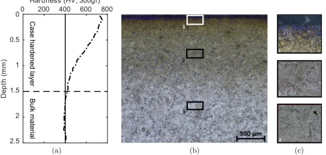
surface (a) and at bulk (b) . . . 23 Figure 4.2 (a) Micro-hardness (b,c) and microstructure gradients of case hardened
E-16NiCrMo13 steel . . . 23 Figure 4.3 Schematic representation of the vibratory peening machine, front view.
The unbalanced shafts rotate and induce the tub’s vibrations. The movement sets the media into an up and down motion. The media impact the part, inducing the peening and finishing effects . . . 25 Figure 4.4 4-strips holder, flush with media surface . . . 26 Figure 4.5 4-strips holder, with different types of specimens. Letters correspond
to positions on the strips-holder . . . 26 Figure 4.6 Actual vibratory peening machine, running with cover . . . 26 Figure 4.7 Microhardness measurements on samples . . . 28 Figure 4.8 Average arc heights of strips treated with VP process and their 95%
confidence intervals as a function of processing frequency for a process-ing time of 8 minutes and for a four-strips holder depth of 178 mm (the depth is presented on Figure 4.4). The mean and confidence intervals were computed from 4 strips . . . 28 Figure 4.9 Saturation times and intensities with their 95% confidence intervals,
for a strip-holder at a processing depth of 178mm (see Figure 4.4) and masses of media of 555 kg and 792 kg . . . 30
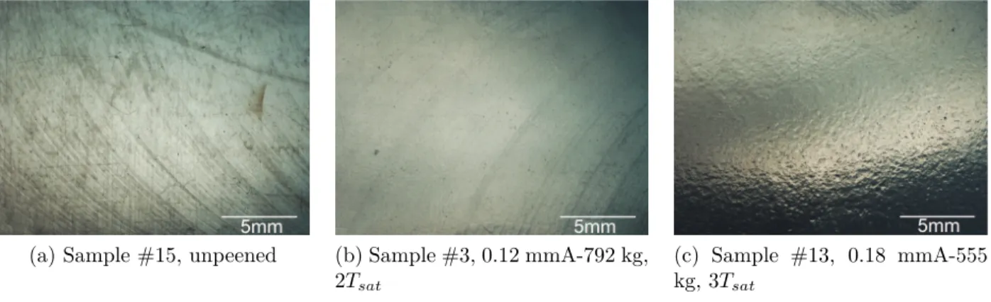
Figure 4.10 Ra measurements for Ti-6Al-4V samples, for mass of media-frequency couples of 792 kg-23 Hz(a), 792 kg-25 Hz and 555 kg-47 Hz (b) and 792 kg-30 Hz (c). Subfigure d) plots the averaged Ra as a function of intensity, for a peening time of 2Tsat . . . 32 Figure 4.11 (a), (b) and (c) are Ti-6Al-4V surfaces obtained with an optical
micro-scope, magnification 6.7X . . . 33 Figure 4.12 Roughness parameters before and after processing for Ti-6Al-4V. Ra
(a), Rsk (b), Rku (c), RSm (d), and Rt (e) have been averaged over all samples . . . 34 Figure 4.13 Residual stress profiles for different peening intensities for Ti-6Al-4V
(792 kg of media, processing time of 2Tsat) . . . 35 Figure 4.14 Residual stress profiles for Ti-6Al-4V samples peened at 0.18 mmA for
media mass-frequency couples of 792 kg-25 Hz and 555 kg-47 Hz . . . 35 Figure 4.15 Residual stress profiles for Ti-6Al-4V peened at 0.18 mmA for different
processing times (12, 24 and 36 minutes) for media mass-frequency couples of 555 kg-47 Hz . . . 36 Figure 4.16 Hardness profiles measured on the cross-section for Ti-6Al-4V samples
peened at different intensities and for a mass of media and peening time of 792 kg and Tsat . . . 37 Figure 4.17 Surface hardness measurements and their 95% confidence intervals for
Ti-6Al-4V samples for different peening conditions . . . 37 Figure 4.18 Comparison of shot peening induced and vibratory peening induced
residual stress profiles of Ti-6Al-4V samples treated at 0.12 and 0.18 mmA . . . 38 Figure 4.19 Rameasurements for E-16NiCrMo13 samples, for mass of media-frequency
couples of 792 kg-23 Hz(a), 792 kg-25 Hz and 555 kg-47 Hz (b) and 792 kg-30 Hz (c). Subfigure d) plots the averaged Ra as a function of intensity, for a peening time of 2Tsat. An intensity of 0 corresponds to the unpeened specimen . . . 39 Figure 4.20 (a), (b) and (c) are E-16NiCrMo13 surfaces obtained with an optical
microscope, magnification 6.7X . . . 40 Figure 4.21 Roughness parameters before and after processing for E-16NiCrMo13.
Ra (a) value is the mean of samples’ Ra peened at t ≥ 2Tsat, Rsk (b),
Rku (c), RSm (d), and Rt (d) have been averaged over all samples . . 41 Figure 4.22 Residual stress profiles for different peening intensities for E-16NiCrMo13
Figure 4.23 Residual stress profiles for E-16NiCrMo13 samples peened at 0.18 mmA for media mass-frequency couples of 792 kg-25 Hz and 555 kg-47 Hz . 42 Figure 4.24 Residual stress profiles for E-16NiCrMo13 peened at 0.18 mmA for
dif-ferent processing times (Tsat, 2Tsat and 3Tsat) for media mass-frequency couples of 555 kg-47 Hz . . . 43 Figure 4.25 Hardness profiles measured on the cross-section for E-16NiCrMo13
samples peened at different intensities and for a mass of media and peening time of 792 kg and Tsat . . . 44 Figure 4.26 Surface hardness measurements and their 95% confidence intervals for
E-16NiCrMo13 samples for different peening conditions . . . 44 Figure 4.27 Comparison of shot peening induced and vibratory peening induced
residual stress profiles of Ti-6Al-4V samples treated at 0.12 and 0.18 mmA . . . 45 Figure A.1 Calibration curves of force indentation for both materials . . . 57
LIST OF ABBREVIATIONS
SP Shot Peening VP Vibratory Peening VF Vibratory Finishing VD Vibratory Deburring HCF High Cycle Fatigue
LIST OF APPENDICES
Appendix A MEASUREMENT METHODS FOR HARDNESS AND RESIDUAL STRESSES . . . 56
CHAPTER 1 INTRODUCTION
Conventional shot peening is a well-known surface treatment used to enhance the fatigue life of metallic parts. The process consists in impacting a metal part with high velocity spher-ical shots. The impacts plastspher-ically deform and strech the surface, which induces a layer of compressive residual stresses and cold working. Shot peening retards the initiation and prop-agation of cracks, and hence increases fatigue life. This beneficial effect is counterbalanced by the increase of roughness that creates stress concentrators, which is detrimental to fatigue life. A surface finishing processing step is often required after shot peening to improve the resulting poor surface finish by smoothing it [1].
Vibratory finishing is a widely deployed process developed in the 1950s for polishing and deburring parts [2]. The process is applied with a container filled with polishing media in which the treated part is inserted. A vibrating system creates a periodic motion that shakes parts and media. The media mechanically polishes the parts’ surface and improves its surface finish.
Vibratory peening is a vibratory finishing process in which the parts are fixed in the tub. When compared to vibratory finishing, having the part fixed in the tub increases the media impacting velocity, leading to higher energy transmitted to the part’s surface. The process induces compressive residual stresses and work hardening on the near surface layer similar to those resulting from the shot peening process, without damaging the surface quality (production of a rough surface). The process combines the beneficial effects of both shot peening and vibratory finishing processes. Furthermore, vibratory peening can be more suitable for complex parts than shot peening, as demonstrated by Feldmann et al. for full blisk-rotors [3].
The purpose of this study was to assess the vibratory peening process potential to either replace or improve on the conventional shot peening process. This research is therefore essential to confirm the process’ potential and lay the bases for forthcoming studies that would be aimed to thoroughly investigate its effects on target materials.
This research was done in collaboration with Safran Aerospace Security and Defense and VibraFinish Ltd. Safran is a French group, worldwide supplier for the aerospace industry, they provided the Ti-6Al-4V and E-16NiCrMo13 samples studied in this project. VibraFinish Ltd is a Canadian SME based in Mississauga and specialized in vibratory finishing, shot blasting and other finishing processes. They committed their experience and their own vibratory peening machine to this research. The rest of the funding was provided by the
National Sciences and Engineering Research Council (project CRDPJ 518968 - 17).
The thesis is divided in 5 chapters. Chapter 2 is an overview of the public literature covering the vibratory peening process. Chapter 3 presents the scientific objectives pertaining to this work and identified from the literature survey. Chapter 4 is an article submitted to the Journal of Materials on Processing Technologies and gathers the experimental work and results. A general discussion and a general conclusion are presented respectively in Chapters 5 and 6. Appendix A presents the measurements methods for the results presented in Chapter 4.
CHAPTER 2 LITERATURE REVIEW
2.1 Conventional shot peening 2.1.1 Process presentation
Shot Peening (SP) is a cold-working process that consists in projecting shots onto a metallic part, at high velocities. The shots impacting the surface transmit energy that produces plas-tic deformation. This deformation streches a surface layer about few hundreds of microns thick. As the core of the material is not deformed, a residual stress field is induced in the material, leading to compressive residual stresses in the sub-surface layer and tensile residual stresses in the core. The compressive stresses act as closure stresses that delay crack initiation and propagation [4]. The SP process also creates work hardening that induces a resistance to plastic deformation and specifically around the crack tip. However, the SP process induces roughness which has a detrimental effect on fatigue life [5]. The enhancement of fatigue life with shot peening is therefore a balance between favorable and detrimental effects. The use of optimal conditions can improves fatigue lives up to 50 times [6], when compared to as-machined parts, or yields endurance fatigue limits 80% higher [7].
2.1.2 Control parameters
Shot peening relies on two process control parameters: Almen intensity and coverage. Almen intensity is a standard testing procedure and consists in shot peening small strips of SAE 1070 steel, for different processing times. The strips are peened in a standardized fixture (Figure 2.1a) and their deflection is measured once they are taken out of the fixture with a standardized Almen gauge (Figure 2.1b). The procedure is repeated for different processing times and the arc height as a function of peening time is plotted as a saturation curve (Figure 2.1c). As described in standard SAE J443 [8], at least four points are needed to obtain the saturation curve. The saturation time is defined as the specific time after which doubling the peening time increases the arc height by 10%. The Almen intensity is the arc height at the saturation time.
The Almen intensity is measured with three different types of strips, namely N, A and C. These strips vary in thickness and are depicted in Figure 2.2. The change in strips’s thickness allows a larger range of measurable Almen intensities. The Almen intensity measured on A-type strips is described by the mmA unit. Almen intensity is specified with these strips and
depends on the target application.
Coverage of a shot peened surface is defined by SAE J2277 [10] as the ratio (in percent-age) of the surface indented by the shots to the total surface. Coverage is determined visually by an experimented eye or by computer assisted image analysis. Full coverage is set at 98%. Coverage values above 100% are multiples of the peening time required to reach 98% coverage.
2.1.3 Typical surface roughness and residual stresses induced by shot peening Liu et al. [11] treated Ti-6Al-4V specimens at different intensities and 100% coverage. Figure 2.3a shows the resulting average roughness for different peening treatments. Xie et al. [12] peened Ti-6Al-4V samples at 0.20 mmA and 100% coverage. It can be observed that the
(a)
ARC HEIGHT
(b)
Processing time (min)
Arc height (mm)
experimental data saturation curve
Saturation time (Tsat) 2*T
sat Intensity (I)
1.1*I
(c)
Figure 2.1 a) Flat strip on its holder, side view. b) Strips on the Almen gauge, measurement of arc height, side view. c) Saturation curve and Almen intensity calculation, as per SAE J443 [8] 76.6 75.6 19.05 18.85 0.81 0.76 1.32 1.27 2.41 2.36
C
A
N
Figure 2.2 Maximal and minimal dimensions of the different Almen strips, in mm, as per SAE J442 [9]
Almen intensity has a significant influence on target’s roughness, which increases with the intensity. Figure 2.3b shows the resulting residual stress field. The depth of the compressive layer is about 130 µm and the maximum of compressive stress is located 15 µm under the surface. The yield stress of Ti-6Al-4V is 880 MPa. It can be noted that the maximum compressive stress is about 93% of the yield stress.
It should be noted that no data was found for the shot peening of E-16NiCrMo13, or similar materials in the literature, in a range of Almen intensity close to that investigated in this work (0.12 mmA- 0.25 mmA).
Unpeened 0.15-0.20 mmA 0.15-0.20 mmA 0.20-0.28 mmA
Roughness R a ( µ m) 0 1 2 3 4 5 6
(a) Average roughness Ra of Ti-6Al-4V samples after shot
peening at different intensities and 100% coverage [11]
(b) Residual stress profile of Ti-6Al-4V samples af-ter shot peening at 0.20 mmA and 100% coverage [12]
2.2 Vibratory finishing
2.2.1 Mass finishing processes
Mass finishing process simultaneously treats many components made of metal and other ma-terials to induce effects like deburring, surface smoothing, edge break, stock removal, surface preparation, etc. Mass finishing processes have been used in the industry since the 1900s [13], but tumbling barrels have been found from the time of ancient Chinese and Egyptians. A mass finishing process consists in treating parts in a recipient filled with abrasive and/or non-abrasive media. A periodic motion is applied to the recipient, creating shocks and im-pacts between media and parts. These imim-pacts alter the surface and sub-surface properties. The media can be lubricated to avoid heating the parts and to clean the dust from the pol-ishing that could damage the surface.
Mass finishing is often required as a final treatment, either prior to final assembly for me-chanical purposes or for aesthetic ones [1]. Mass finishing can also be part of the production line as a final step. Furthermore, these processes deliver highly consistent and repeatable results.
2.2.2 Vibratory finishing process
Vibratory Finishing (VF) has been used in the industry since the 1950s and widely accepted in the 1960s. However, very few scientific studies of the process can be found in the literature before 1975. A vibratory finisher consists in a container filled with media (Figure 2.4) and mounted on springs. A vibration generator is attached to the container and is constituted of one or two unbalanced shafts that are driven by a motor. Controlling the motor rotation speed, the mass of media, the stiffness of springs, etc, creates different vibration modes that fluidize the media. A mix of water and lubricant, which is called compound, is often added in the container and used to clean the media and parts. It also favors the flow circulation by lubricating the media bed and reduces the possible heat increase. Some compounds contain acids and are chemically reactive, which accelerates the metal finishing process [14]. The use of lubricant yields better surface finish because the media tends to slide more on the workpiece and the lubricant increases the contact surface, decreasing the abrasive effect. The nature of the media is an important key of the process and its choice depends on treatment’s objectives [15]. There is therefore a wide range of shape, size, material and media roughness. Plastic, ceramic and steel media are the most widely used.
Figure 2.4b (tub-type). The bowl-type process creates a 3D media flow while the tub-type process creates a 2D flow. Tub-type processes can treat larger parts than the bowl-type process. Hashimoto et al. [16] studied the influence of eccentric weights disposition in a bowl-type finisher on media flow through analytical and experimental means. The authors proposed an optimal disposition (67◦ between the weights) to maximize machine performance and chose the average media velocity as the control parameter. Naeini et al. [17] studied the media flow in a tub-type finisher using transparent plates to create an easily observable one-ball layer. The authors used the same setup to study multiple layers of media [18]. They compared 2D discrete element simulations with experimental results and found that the model could predict the circulation trends quite accurately. They varied the number of shots in the system and could predict the shots velocities within 10% of experimenally measured values for 50 and 400 shots. Hashemnia et al. [19] studied the media flow of a tub-type finisher using a visco-plastic finite element continuum model. The authors implemented the model using parameters calculated from a discrete element model of the media bed. They demonstrated that a continuum model produced results comparable to a discrete model, with an average difference of 15% with experimental data, for one eight of the computational time.
(a) Bowl-type [20] (b) Tub-type [21]
2.3 Vibratory peening 2.3.1 Process presentation
The vibratory peening machine is a vibratory tub-type finisher where the part is fixed to the container, as shown in Figures 2.5 [22] and 2.6 [23] . The relative velocity between the media and the part is therefore increased, which leads to stronger impacts. The machine is composed of a container filled with spherical and non-abrasive media (to avoid stock removal), a suspension system (springs or airbags) and a vibration system (Figure 2.5). The vibration system induces a motion inside the machine, transmitting energy to the container and to the media. Vibrations are created using unbalanced shafts put into rotation by a motor and the amplitude of vibrations can be modified by changing the shafts’ balance and the suspension stiffness. The vibrations frequency is controlled by the motor rotation speed and hardly goes above 60 Hz. Lubricant is sprayed through nozzles and cleans the media from dust and reduces heating. The impacts between the part and the media are mechanically plastifying its surface, which induces modifications in a subsurface layer.
Vibratory peening is relatively new and very few dedicated studies have been reported in the literature [3, 22, 23, 24, 25] so far. Some authors have developed numerical models for predicting the media dynamics [26, 27]. While these studies provide a sound scientific ground for a better understanding of the process, predicting its effects remains a challenge.
Figure 2.6 Picture of a strip holder inside the VP machine filled with steel media [23]
A number of authors also related the process parameters to resulting roughness, residual stresses and fatigue life [3, 22, 25]. These studies present the process’ effects on aluminum alloys AA7050-T7451 and AA3003-H14 [22, 25], titanium alloy Ti-6Al-4V [24] and Inconel 718 [3]. Wang et al. vibratory peened a sintered 316LSC stainless steel and showed that the process increased the corrosion performance [28].
2.3.2 The use of Almen(-like) intensity and coverage in the VP process
Baghbanan et al. [20] vibratory peened aluminum (AA6061 and AA1100) and copper strips similar to Almen strips. The authors showed lubricant trapped between the strip and the holder increases the strip’s stiffness, leading to a greater curvature than applying the process in dry conditions. This observation suggests that care must be taken if lubricant is found beneath the strip after processing.
Ciampini et al. [23] relied on Almen-like aluminum strips to characterize the VP process. The strips were vibratory peened under different processing conditions and impact velocities have been measured with a force sensor. The authors observed that higher impact velocities led to higher arc heights and concluded that the adapted Almen system was appropriate to characterize the process’ efficiency.
aluminum strips. The authors used the finite element technique to calculate curvature as a function of residual stresses distribution. They found that curvature was a unique function of cumulative absorbed energy for a given set of ball radius, material model and strip thickness. The fact that authors relied on Almen-like strips not made of standardized SAE 1070 steel makes the comparison of resulting residual stresses and roughness with those of conventional shot peening impossible. Therefore, the question of the capability of the VP process to reach intensities comparable to those used in aerospace industries has yet to be addressed.
2.3.3 Comparison of VP and VF in terms of surface characteristics and fatigue lives.
Gane et al. [24] compared the fatigue lives and roughness of Ti-6Al-4V flat notched samples (Kt = 1.5) treated with VF and VP. VP was realized with a mixture of 4 to 7 mm diameter hardnened steel balls. The vibrations amplitude was of 4 mm and the processing time was one hour. The VF process used 10 mm triangular ceramic abrasive media. The amplitude of vibrations was 2.5 mm and the processing time was one hour. Fatigue tests were carried out at a maximum stress of 458 MPa (52% of the yield stress), a stress ratio R=-0.2 and a frequency of 20 Hz. The authors observed that VP led to a 104% High Cycle Fatigue (HCF) life improvement, when compared to that obtained with VF. Furthermore, VP reduced the scatter in the fatigue testing results, when compared to VF. The authors measured residual stresses and found that the maximum compressive stress was 41% higher for VP, when compared to VF. This is explained by a higher energy transmitted to the parts due to higher impacting velocities. Furthermore, the maximum compressive stress was deeper and the position where the profile became positive was deeper as well for VP, when compared to that resulting from VF. The roughness measurement showed that average roughness parameter
Ra was 8% higher with a lower scatter in VP than that observed in VF.
This study suggests that VP can potentially lead to better HCF lives than VF. This result could be explained by the fact that the surface finish was almost identical for both processes while VP induced more compressive residual stresses than VF.
2.3.4 Comparison of VP and SP in terms of surface characteristics, residual stresses and fatigue lives.
Gane et al. [24] compared the effects of different surface treatments in terms of fatigue life, roughness and residual stresses on Ti-6Al-4V plates. The authors treated and fatigue tested flat notched specimens (Kt= 1.5). The samples underwent fatigue tests at a maximum stress
of 458 MPa (52% of the yield strength), a stress ratio R=-0.2 and a frequency of 20 Hz. They compared vibratory deburring (VD), shot peening at two different intensities (0.18 mmA and 0.43 mmA) and vibratory peening. VD is similar to VP since the part is fixed in the tub and the only difference is that the authors used ceramic media for VD and steel media for VP. VP and VD led to similar roughness Ra, about 75% lower than SP at 0.18 mmA and 90% lower than SP at 0.43 mmA. The residual stresses resulting from the application of VP were very close to those resulting from shot peening, but went deeper (+40% at -50 MPa), when compared to SP at 0.18 mmA. SP at 0.43 mmA induced higher residual stresses, when compared to VP. The VP samples had HCF lives similar to those of samples shot peened at an intensity of 0.43 mmA, for a lower scatter. However, the VP samples had better HCF lives than those shot peened at an intensity of 0.18 mmA. The VD samples had a large scatter and an average HCF lower than that of SP samples.
Sangid et al. [22] compared the effects of SP and VP on AA7050-T7451 samples in terms of roughness, residual stresses and fatigue life. The authors treated and studied flat notched specimens having a stress concentration factor Kt= 1.5. The samples were tested in HCF at a maximum stress of 284 MPa (61% of the yield stress), a stress ratio R=0.1 and a frequency of 2 Hz. VP led to a better fatigue life with a larger scatter, when compared to that obtained from SP. The integral of the compressive residual stresses was higher for SP than for VP (+80%) while the roughness parameter Ra was higher for SP(+250%). SP led to higher roughness because its highly energetic impacts occurred on small area and induced deep dimples. By opposition, the VP process relies on larger shots traveling at lower velocities, which leads to wider and less deep craters.
Feldmann et al.[3] compared the VP and SP processes effects on full blisk-rotors made of a nickel based alloy. The authors studied two kinds of media: a “hard media” and a “soft media” (the media material was not disclosed in their works). It was found that the VP process led to an average roughness Ra of 0.15 µm when using the hard media and 0.21 µm when the soft media, while shot peening led to an average roughness of 0.41 µm. Residual stresses measurements showed that applying the VP process with hard media yielded compressive stresses in the subsurface layer similar to those obtained from SP. Surface compressive residual stresses were higher after SP (+13%). However, the higher compressive stresses were similar for both processes and the residual stress profile resulting from VP was deeper (+85% at 5% of the maximum stress), when compared to SP. The samples treated with soft media showed a lower high cycle fatigue strength than samples treated by SP (-16%). Note that the fatigue results obtained with the hard media were not presented.
This somewhat limited survey suggests that shot peening led to globally higher compres-sive stresses but vibratory peening yielded much better surface finishes. Shot peening yielded
better or similar fatigue lives than vibratory peening. However, most of these studies did not compare processes of similar intensities, which implies that these observations must be confirmed by more rigorous studies.
2.4 Influence of VP process parameters on the process’s effects 2.4.1 Roughness
Roughness parameters like the average roughness Ra, the skewness Rsk, the kurtosis Rku, the mean peak width RSm and the total height of the profile Rt, are calculated as
Ra = 1 ls Z ls 0 |Z(x)|dx; Rq= 1 ls Z ls 0 Z2(x)dx; Rsk = 1 Rq3 1 ls Z ls 0 Z3(x)dx; Rku = 1 Rq4 1 ls Z ls 0 Z4(x)dx; RSm = 1 m m X i=1 XSi; Rt= max la Z − min la Z (2.1)
where Z is the profile’s height, lsthe sampling length, la the acquisition length (la = 5ls). {XSi, i ∈ [1, m]} is the ensemble of profile elements within ls. Some of these parameters are schematized in Figure 2.7.
Hashimoto [30] developed an analytical model to predict average roughness Ra evolution as a function of time as 0 Acquisition lenght Sampling lenght Xs1 Rt Ra
Ra(t) = (Ir− Dr)e −t
T + Dr (2.2)
where Dr is the roughness threshold, Ir is the initial roughness and T is a time con-stant that depends on process parameters. This model is based on the fact that a threshold roughness Dr exists and is intrinsic to the VP process, and that the roughness evolution rate increases when the difference between actual Ra and Dr increases. The threshold roughness not only depends on the working material and media properties, but also on machine proper-ties. According to this model, increasing the processing time should not degrade the surface roughness.
Domblesky et al. [31] vibratory finished aluminum, brass and steel parts using ceramic rough media and obtained results in agreement with Hashimoto’s model. Walton et al. [32] vibratory peened Ti-6Al-4V samples in a bowl type finisher for different processing times. The authors showed that the surface roughness evolution was well represented with Hashimoto’s model.
Sangid et al. [22] studied the influence of vibrations frequency and amplitude on rough-ness. The authors treated 7050-T7451 aluminum samples in a tub-type machine with ceramic media. Their analysis showed that increasing vibrations frequency increased roughness (Ra of 0.75 µm at 20 Hz and of 0.83 µm at 32 Hz). It also showed that increasing vibrations amplitude yielded a slightly rougher surface (Ra of 0.77 µm at 2.4 mm and of 0.81 µm at 2.8 mm).
Wang et al. [33] investigated the lubrication and the media roughness effects on the roughness of vibratory finished part. The authors treated aluminum AA1100-O and AA6061-T6 samples in a bowl-type machine with ceramic media. The authors found that vibratory finishing under dry conditions led to higher roughness (Ra of 2.35 µm, using 9 mm ceramic media and after processing AA 1100-O samples for 80 minutes) than vibratory finishing under lubricated conditions (Ra of 0.56 µm, using 9 mm ceramic media and after processing AA1100-O samples for 80 minutes). The authors investigated the effect of media roughness on parts roughness using ceramic media having different surface characteristics (Ra=15.4 µm;
Rsk=-0.43 and Ra=13.8 µm; Rsk=-0.156). The authors concluded that the rougher media led to a higher roughness (Ra=2.36 µm after processing AA1100-O samples for 80 minutes under dry conditions), when compared to the smoother media (Ra=0.58 µm after processing AA1100-O samples for 80 minutes under dry conditions).
process and found that hard media led to lower roughness (0.15 µm), when compared to that resulting from the use of soft media (0.21 µm).
2.4.2 Hardness
Wang et al. [33] studied hardness evolution of vibratory finished AA1100-O and AA6061-T6 samples. The authors treated AA1100-O and AA6061-T6 samples under dry and detergent-wet conditions and found that the dry condition led to higher hardness with a greater scatter (146 HV on AA6061-T6 vibratory finished for 80 minutes), when compared to lubricated con-ditions (116 HV on AA6061-T6 vibratory finished for 80 minutes). The authors investigated the effect of media roughness on hardness using ceramic media having different surface char-acteristics (Ra=15.4 µm; Rsk=-0.43 and Ra=13.8 µm; Rsk=-0.156). The studies suggest that the rougher media led to a higher hardness increase (+13 HV on AA1100-O vibratory finished samples for 80 minutes under wet conditions), when compared to the smoother media (+4 HV on AA1100-O vibratory finished samples for 80 minutes under wet conditions). Glob-ally, hardness increased with the processing time, but few experiments showed a hardness decrease after a certain processing time. The same materials were investigated by Baghbanan et al. [20]. The authors concluded that hardness globally increased with processing time but observed some exceptions as well.
2.4.3 Residual stresses
Few authors investigated the residual stresses resulting from vibratory finishing / peening processes. Feldmann et al. [3] measured the residual stress field after processing airfoils made of a nickel based alloy with a bowl type vibratory peener. They used soft and hard media and showed that hard media induced deeper and more compressive residual stresses. Sangid et al. [22] measured residual stresses profiles in vibratory peened samples made of 7050-T7451 aluminum under different conditions. The authors used the integral of the profile to present their results. That scalar can also be a measure of the total strain energy. The authors found that frequency had a strong influence on that parameter. An increase of processing frequency led to an increase of compressive residual stresses. The influence of amplitude was found to be insignificant on the residual stresses integral. The authors also observed that samples having the most compressive residual stresses were also those with the worst surface finish. The authors have also shown that normal impacts, when compared to tangential impacts, produced larger residual stresses, but rougher surfaces. Ciampini et al. [34] treated AA6061-T6 disks equipped with sensors under different mass of media and material conditions and measured the impacting forces. The authors found that reducing the mass of media from
112 kg to 91 kg led to a more energetic process. The author related this phenomenon to the increase of vibrations amplitude.
2.4.4 Fatigue life
Sangid et al. [22] shot peened and vibratory peened flat notched specimens having a con-centration factor Kt = 1.5. The samples were made of AA7050-T7451. They were tested in HCF at a maximum stress of 284 MPa, a stress ratio R=0.1 and a frequency of 2 Hz. The authors found that all the vibratory peened samples had a higher fatigue life than the shot peened samples. The authors found that the VP processing conditions had a strong influence on the fatigue life results. For example, using rough ceramic media was shown to increase the scatter in the fatigue life results, when compared to worn ceramic media. The authors have also varied the samples positions and orientations and found that normal impacts induced the best fatigue life improvement, despite the fact they produced the roughest surfaces.
2.4.5 Summary
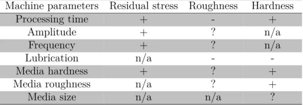
Table 2.1 summarizes the influence of machine parameters on roughness, residual stresses and hardness.
Table 2.1 Effects of processing parameters on residual stresses, roughness and hardness Machine parameters Residual stress Roughness Hardness
Processing time + - +
Amplitude + ? n/a
Frequency + ? n/a
Lubrication n/a -
-Media hardness + ? +
Media roughness n/a ? +
Media size n/a n/a ?
Legend
+ = an increases induce an increase - = an increase induces a decrease ? = no trend can be observed from data n/a = no data available
CHAPTER 3 ANALYSIS OF LITERATURE AND OBJECTIVES
The literature survey led to the following findings:
• The effects of VP have been studied on very few alloys, namely aluminum AA7050-T7451 and AA3003-H14, titanium Ti-6Al-4V, a nickel based alloy and sintered 316LSC stainless steel.
• Processing time, amplitude, frequency, lubrication, media hardness, roughness and size, part’s position and orientation within the tub have been shown to have an influence on residual stresses, roughness and hardness. However, the limited amount of publicly available studies prevent from drawing general and rigorous conclusions.
• Vibratory peening induces compressive residual stresses beneficial for fatigue life (crack closure mechanism) and yields much better surface finish than shot peening.
• Almen(-like) intensity has been demonstrated as a relevant control parameter for VP. However, the use of standardized Almen strips has not been reported in the litera-ture. Therefore, the range of Almen intensities attainable by the process has yet to be determined.
• The effects of VP and SP processes have not been compared using a common control parameter (as Almen intensity, for example).
• Very few studies have demonstrated the fatigue life improvement resulting from vibra-tory peening.
These observations rise the following questions:
1. Is the vibratory peening process able to achieve a range of Almen intensities comparable to those obtained from the shot peening process ?
2. What are the effects of vibratory peening on roughness, residual stresses and hardness for aerospace materials ?
3. Could vibratory peening be an efficient process for fatigue life improvement ?
1. Demonstrate the capability of the vibratory peening process to reach Almen intensities in the range of 0.12 mmA and 0.25 mmA, which is the range typically used in aerospace. 2. Study the influence of vibratory peening on roughness, hardness and residual stresses for Ti-6Al-4V and E-16NiCrMo13. These materials were chosen by Safran and are used in landing gears and airplane engines.
3. Compare the effect of vibratory peening and shot peening processes for similar Almen intensities.
All these objectives are addressed in Chapter 4. Chapter 4 is a journal paper submitted to the Journal of Materials Processing Technology on the 2018/01/27. The authors are Jawad Badreddine, Brian McGillivray, Hong Yan Miao, Martin Lévesque and myself as first author. My role in this paper was to carry out all the experiments and lead the paper’s writing. The other authors supervised the works. My contribution to this paper has been evaluated to 90%.
CHAPTER 4 ARTICLE 1: EFFECT OF VIBRATORY PEENING ON THE SUB-SURFACE LAYER OF AEROSPACE MATERIALS Ti-6Al-4V AND
E-16NiCrMo13
Léo Canals, Jawad Badreddine, Brian McGillivray, Hong Yan Miao and Martin Lévesque. Submitted to Journal of Materials Processing Technology on January 27, 2018.
4.1 Abstract
Conventional Shot peening (SP) is a widely used fatigue life improvement process by impact-ing the metal component with high velocity shots. The plastic deformation induces a layer of compressive residual and cold work which retards the crack initiation and propagation. How-ever, shot peeing increases surface roughness which acts as stress concentrator and decreases fatigue life. Vibratory finishing (VF) is a mass finishing process in which components are inserted in an oscillating bowl, or tub, containing polishing media. The media flow around the component polishes its surface and decreases its roughness. Vibratory peening (VP) is a modified vibratory finishing process that induces compressive residual stresses comparable to those induced by shot peening, but for a much better surface finish. In this paper, the effects of vibratory peening on surface roughness, residual stresses and hardness were investigated on two aerospace materials, titanium alloy Ti-6Al-4V and carburized steel E-16NiCrMo13. Studied process parameters are frequency, media mass and processing time. A study of Almen intensity as a function of machine parameters has been carried out to define the machines’ parameters leading to the target Almen intensities of 0.12 mmA, 0.18 mmA and 0.25 mmA. The influences of media mass and frequency on peening intensity have been investigated. The study results show that the VP process can deliver the targeted intensities consistently. Roughness measurements show that for both studied materials, VP produces good surface roughness with a consistent average roughness value in the range of 0.3-0.4 µm. The residual stress profiles produced by VP are comparable to which produced by conventional SP at same Almen intensity. Compared to conventional SP, VP led to higher maximum compres-sive values for steel and equal for titanium, while deeper depths of the comprescompres-sive region (+126% for steel). Hardness measurements show that VP has limit influence on a layer with depth of 70 µm. In general, the VP process is capable of consistently produce a beneficial layer of compressive residual stress together with a good surface finishing which could greatly improve fatigue properties on aerospace components.
4.2 Keyword
Vibratory peening, residual stresses, roughness, hardness, fatigue life
4.3 Introduction
Conventional shot peening consists in projecting hard particles at high velocity onto a duc-tile metallic surface. The process induces compressive residual stresses, hardening and mi-crostructural changes that delay fatigue crack initiation and propagation. The process also increases surface roughness, which increases stress concentration and is detrimental for fa-tigue life. Shot peened parts are often subjected to surface finishing treatments like vibratory finishing, low intensity peening [35] or peening with smaller shots [36] to improve their surface characteristics.
The conventional shot peening process is specified mainly by two process variables: Almen intensity and coverage. The Almen intensity is related to the kinetic energy, per second, transferred to the part and is measured by submitting a thin standardized steel strip (SAE J442 [9]), held in a standardized Almen holder, to the process. The residual stresses induced by the process progressively bend the strip and its arc height is measured with a standardized Almen gage as a function of the peening time. The Almen intensity is defined as the arc height when doubling the peening time increases the arc height by 10%. Almen strips come in three types of various thicknesses, namely A (1.3 mm), C (2.38 mm) and N (0.79 mm). Coverage is related to the peening time and is defined as the ratio of the surface covered by dimples over the total treated surface. 98% coverage is referred to as full coverage and any coverage value above 100% is a multiple of the peening time required to reach full coverage. Vibratory Finishing (VF) is a mass finishing process in which components are inserted in an oscillating bowl, or tub, containing polishing media. The vibrations create a flow in the media that abrades and polishes the parts. The process has been developed in the 1950s and widely applied since the 1960s [37]. In addition to improve surface finish, the process induces compressive residual stresses of lower intensity than those resulting from shot peening [24]. The process effects in terms of material removal [31], roughness [20], edge rounding [38] and hardness [33] have been studied in the open literature.
Vibratory Peening (VP) is a process derived from vibratory finishing that consists in in-serting a fixed part into an oscillating bowl filled with polishing media. The relative movement between the treated parts and media is significantly increased and leads to higher impact velocities, when compared to VF. The process induces surface modifications in a small sub-layer of about 400 micrometers [22]. The process is somewhat similar to conventional shot
peening in the sense that the impacting media induces compressive residual stresses [25] and work hardening [33]. However, the VP process results in a much smoother surface finish than SP. The process could therefore be a potential candidate to either combine peening and polishing into a single step or even to improve fatigue life, when compared to conventional shot peening.
The VP process is relatively new and few dedicated studies have been reported in the literature since the 2000s, mostly through conferences proceedings. Some authors adapted the Almen intensity system used with the SP process to the VF and VP processes. Ciampini et al. [23] used aluminum 3003-H14 strips, similar in length and width to Almen strips (as per SAE J442 [9]) but with two different thicknesses. One thickness corresponded to the N strip and the other one was thinner (0.62 mm). The authors used these strips to characterize the VP process’ relative aggressiveness with the change of the sample’s position within the tub and the mass of media. Baghbanan et al. [20] also used aluminum strips (AA6061 and AA1100) and copper strips to characterize the VF process intensity. By varying the lubrication conditions, the authors found the use of lubricant led to higher peening intensities. They found that applying a grease film between the strips and the holder led to higher curvatures under dry conditions, when compared to strips without the grease film. The authors confirmed that wet conditions were less aggressive (the impact strength is reduced by the presence of a lubricant film between the part and the media), but gave higher peening intensities due to lubricant behind the strips, when compared to dry conditions.
Gane et al. [24] compared the fatigue lives and roughness of Ti-6Al-4V samples peened with SP and VP. The authors treated and fatigue tested flat notched specimens (Kt = 1.5). Samples were shot peened at 0.18 mmA and 0.43 mmA, with 100% coverage, using CS 280 hard cast steel shots. VP was performed with 4 to 7 mm diameter hardened steel ball bearings for one hour. The samples underwent fatigue tests at a maximum stress of 458 MPa (52% of the yield strength), a stress ratio (minimum stress over maximum stress) R=-0.2 and a frequency of 20 Hz. The authors observed that VP led to a 12% High Cycle Fatigue (HCF) life improvement (2.1 x 10⁵ cycles), when compared to the fatigue lives obtained after shot peening at an intensity of 0.43 mmA (1.9 x 10⁵ cycles). Furthermore, VP reduced the scatter in resulting fatigue lives, when compared to SP. The authors also measured residual stresses and found that the maximum compressive stresses were of the same magnitude of those resulting from SP at an intensity of 0.18 mmA. However, the residual stresses induced by VP were deeper in the affected layer than those induced by SP.
Sangid et al. [22] experimentally studied the impact of VP on the roughness, the residual stresses and the fatigue life of AA7050-T7451 samples. The authors treated and studied flat
notched specimen having a stress concentration factor Kt = 1.5. The samples were tested in HCF at a maximum stress of 284 MPa (61% of the yield stress), a stress ratio R=0.1 and a frequency of 2 Hz. The authors found that low tub frequency and vibrations amplitude yielded better surface finish, while high tub frequency and vibrations amplitude led to more important residual stresses, which in this specific case, led to higher fatigue lives in HCF conditions. The authors also found that the part’s position and orientation within the tub had a significant influence on fatigue life, roughness and residual stresses measurements. Moreover, the authors compared the fatigue life enhancement resulting from the VP process to that resulting from the SP process. The authors averaged the fatigue lives of samples vibratory peened (without providing Almen intenity measurements) to samples shot peened at an intensity of 13 mmA (the media used for the SP process was not specified). The authors found that VP led to a 62% fatigue life improvement(1.5 x 10⁵ cycles), when compared to SP performed at an intensity of 13 mmA (9 x 10⁴ cycles).
This literature survey reveals that processing time, amplitude, frequency, mass and type of media, lubrication intensity, position of the part and its orientation in the tub influence the process effects in terms of residual stresses, roughness and fatigue life. In addition the range of Almen intensities that could be reached by the process has not been studied yet, to the best of our knowledge. This information is very important from an industrial stand-point because it would provide common bases to compare VP effects to those of the widely accepted and standardized SP process. Moreover, to the best of our knowledge, VP-induced hardness variations have never been studied. Hardness is a key driver in fatigue life and having this information would provide sound grounds to assess the process’ potential to improve fatigue. Finally, the number of studies related to the application of VP on titanium is somewhat limited and non-existent on steel alloys.
Sangid et al. [25] used the measurements of media velocities and frequencies from [22] to simulate the evolution of coverage with time. The authors used aluminium alloy AA7075-T6 properties for their model. They found that for a frequency of 32 Hz, the processing time to reach 95% coverage was of 40 minutes while it was of 60 minutes to reach 99%. The authors concluded that the effects of the VP process saturated after 60 minutes.
The principal objectives of this work were to investigate the range of Almen intensities that can be reached by the process and study its effects, in terms of roughness, residual stresses and hardness on TI-6Al-4V titanium and E-16NiCrMo13 cemented steel alloys. These two alloys are mainly used in gas turbine engines and landing gears and were identified as potential candidates to benefit from the VP process. Section 4.4 presents the materials and methods used in this study. Section 4.5 presents the study of Almen intensity as a function of
process parameters. Section 4.6 presents the effects of the VP process on roughness, residual stresses and hardness, for the two selected materials. The results are then discussed in Section 4.7 and Section 4.8 concludes the work.
4.4 Materials and methods 4.4.1 Materials
The Almen strips processed in this study were A-type strips(76×19×0.8 mm3), 1-S-grade (hardness 450 -490 HV), as specified in standard SAE J442 [9].
A case hardened low alloy steel E-16NiCrMo13 and a titanium alloy Ti-6Al-4V (ASTM 4911N standard) were used for this study. Their chemical compositions are specified in Table 4.1. The Ti-6Al-4V alloy was provided as 8 mm thick laminated plates at an annealed condi-tion, according to the AMS4911N standard [1]. The obtained microstructure is an alpha-beta alloy (Figure 4.1) with a surface and bulk hardness of 350 HV0.1. Its mechanical properties are given in Table 4.2. The E-16NiCrMo13 steel was provided as normalized and annealed 190 mm bars, from which all specimens were extracted and machined. The specimens were then case hardened with low-pressure carburizing equipement, and gas quenched. A cryo-genic treatment was applied to reduce residual austenite. Finally, a stress relieve treatment was done to achieve a surface hardness of 750 HV0.3 and a bulk hardness of 400 HV0.3 at a depth of 1.5 mm from the surface. This represents a carbon concentration gradient, with around 0.7%w at the surface (before grinding) and 0.17%w at the bulk. The obtained mi-crostructure, presented in Figure 4.2, shows martensitic microstructures gradually etched (due to the carbon gradient) representative of that usually observed in case hardened steels. The mechanical properties of the bulk material are also given in Table 4.2.
Fifteen Ti-6Al-4V samples having dimensions of 60.0×18.9×8.0 mm3 and fifteen E-16NiCrMo13 samples having dimensions of 79.9×18.9×8.0 mm3 were submitted to the VP process. The steel specimens were grinded after the case hardening, resulting in an average roughness Ra of 0.7 µm. The titanium specimens were milled (Ra ≈ 0.4 µm). The samples were made thicker than Almen strips to reduce the bending induced by the process.
Table 4.1 Chemical composition of the Ti-6Al-4V titanium Alloy (AMS 4911) and the car-burized E-16NiCrMo13 low alloy steel (ISO 683-17 Grade 16NiCrMo13)
Wt. % Fe Ti Al V Ni Cr Mo C Mn Si P S Cu O
Ti-6Al-4V <0.25 Balance 6 4 - - - <0.2
-(a) (b)
Figure 4.1 As received microstructure of annealed Ti-6Al-4V titanium alloy at surface (a) and at bulk (b) Hardnessk(HV,k300gf) 0 200 400 600 800 Dep th k(m m ) 0 0.5 1 1.5 2 2.5 Bulkkmaterial Casekhardenedklayer (a) (b) (c)
Figure 4.2 (a) Micro-hardness (b,c) and microstructure gradients of case hardened E-16NiCrMo13 steel
Table 4.2 Ti-6Al-4V titanium alloy [39] and carburized E-16NiCrMo13 low alloy steel prop-erties (ISO 683-17 Grade 16NiCrMo13)
Properties Ti-6Al-4V E-16NiCrMo13
Young Modulus (GPa) 114 210
Poisson ratio 0.23 0.28
Density (kg/m3) 4430 7850
Yield Stress at 0.2% (MPa) 880 1000
Ultimate stress (MPa) 950 1350
Surface/Bulk hardness (HV) 350/350 750/400
4.4.2 Vibratory peener and media
A tub type machine built by Vibra Finish Ltd., as schematically depicted in Figure 4.3, was used to treat the samples. Figures 4.4, 4.5 and 4.6 show the actual machine used in the experiments. The oscillatory motion resulted from rotating shafts mounted with eccentric masses. The shafts rotated at the same frequency but in opposite direction. This configuration induced a vertical motion, as shown in Figure 4.3. The tub was mounted on airbags whose pressure was adjusted to control the vibration amplitudes and to ensure the tub’s level. The tub was filled with media and the samples were firmly held in place in a four-strip holder setup shown in Figures 4.4 and 4.5. The pressure in the right-hand side airbags was set 69 kPa (10 psi) higher than that in the left-hand side airbags (Figure 4.6) to ensure the tub’s horizontality (the tub is not balanced due to vibration system). The airbags pressure could be adjusted in the range of 103 kPa (15 psi) to 414 kPa (60 psi). The applied frequency ranged between 1 Hz and 60 Hz.
The tub was filled with AISI Type 1018 carbon steel balls having diameters of 3.18 mm (1/8 in), 4.76 mm (3/16 in) and 6.35 mm (1/4 in) in equal mass proportions (i.e., each ball size accounted for 1/3 of the total media mass). The carbon steel balls had a minimum hardness of 60 HRc. The total media mass varied between 555 kg (1222 lbs) and 792 kg (1745 lbs). The machining coolant Castrol SyntiloTM9828 (a water-based rust inhibitor) mixed with water (50% lubricant to water ratio) was sprayed with 2 nozzles on the media with a flow rate of 1.9 L/min. This compound also served as a media lubricant.
4.4.3 Shot peening
Two specimens for each materials were shot peened intensities of at 0.12 mmA and 0.18 mmA, respectively, with a surface coverage of 125%. The shot peening was conducted using ASR130 steel media (48-52 HRc), projected through a 10 mm straight cylindrical nozzle, at
Vibration mode
Fixture and part
Air bags Media
Shaft Eccentric weights
Direction of rotation
Figure 4.3 Schematic representation of the vibratory peening machine, front view. The unbalanced shafts rotate and induce the tub’s vibrations. The movement sets the media into an up and down motion. The media impact the part, inducing the peening and finishing effects
an angle of 85◦ and a working distance of 180 mm from the specimens surface.
4.4.4 Instrumentations and methods
The mass of media used in the experiments was measured with a scale accurate to 0.227 kg (0.5 lbs). The machine’s vibratory frequency was controlled on its interface by changing the rotatory frequency and the related sensor was accurate to 0.1 Hz. Lubrication was controlled through a flow regulator that adjusted the mixture of water and compound. A four-strips holder was used to simultaneously process multiple strips and samples. A preliminary study revealed that every specimen in the strip holder is subjected to the same peening treatment. Four Almen strips were peened simulataneously for the study presented in section 4.5 while positions A and D (Figure 4.5) were filled with Almen strips to protect the blocks, position B was filled with a E-16NiCrMo13 sample and position C with a Ti-6Al-4V sample in the study presented in Section 4.6.
Almen intensity was measured as per SAE J443 [8] standard on A strips with an Almen gage. The saturation curve was fitted from four arc height measurements, as per standard SAE J2597 [41] as,
h = a(1 − exp−bt) (4.1)
where h was the arc height, t the peening time while a and b were least squares fitting parameters.
Coverage could not be measured as the surface finish was too smooth to identify dimples. Regarding vibratory peened samples, roughness measurements were performed with a
Lubrication nozzle
Steel media
4-strip hodler Polyurethane coating
Fixture depth
Figure 4.4 4-strips holder, flush with media surface
E-16NiCrMo13 sample Ti-6Al-4V sample
A-type Almen strip 4-strips holder
A B
C D
Figure 4.5 4-strips holder, with different types of specimens. Letters correspond to positions on the strips-holder
Protection grid
Airbags Shafts location Cover
Mitutoyo SV-C4000 series profilometer (resolution of 0.05 µm). Regarding shot peened sam-ples, roughness measurements were performed with an Alicona InfiniteFocus G5 microscope by focal variation. Five surface roughness profiles were measured at different locations along the samples major length, for each vibratory peened sample (ten profiles for shot peened ones). In accordance with DIN EN ISO 4288: 1998 standard, a cut-off length of 0.8 mm and a total measured length of 4 mm were selected for vibratory peened samples (cut-off length of 0.8 mm and total length of 8 mm for shotpeened ones) as the roughness was expected to lie between 0.1 µm and 2 µm. Roughness parameters were calculated as per ISO 4287. The calculated parameters were Ra, the average profile roughness (mean of the absolute value of the profile height), Rsk, the profile skewness which measures its asymmetry, Rku, a measure of the profile sharpness and related to the flattening of the surface, RSm, a spacing param-eter which measures the mean profile width distribution and Rt, the total profile height. A skewness value Rsk < 0 means that there are more valleys than peaks while Rsk > 0 means the opposite. A value of Rku > 3 corresponds to a spiked surface while Rku < 3 corresponds to a bumpier surface with rounded peaks.
Samples surfaces were observed under an optical microscope with 6.7X lens.
Residual stresses measurements of vibratory peened samples were carried out by Amer-ican Stress Technologies Inc. with a goniometer Stresstech Xstress 3000 G2R, 7257/7258. The measurements were made according to ISO EN15305, ASTM E915-16 and SAE HS-784 standards. The diffractometer was equipped with a Ti-tube (λ = 0.275nm) and with a Cr-tube (λ = 0.299nm), respectively, for Ti-6Al-4V and E-16NiCrMo13 samples. For the shot peened samples, the measurements were carried out with a goniometer Brüker D8 Omega. The diffractometer was equipped with a Cu-tube and with a Cr-tube, respectively, for Ti-6Al-4V and E-16NiCrMo13 samples.
Vickers hardness measurements were performed with a MVK-H0 machine (Akashi Corp). The surfaces were polished before indentation by manual and automatic methods. A force 100 gf was selected for Ti-6Al-4V and a force 300 gf was selected for E-16NiCrMo13. All the measurements were performed according to ASTM E384 standard. A minimum of five indents have been made for each depth. Indent diagonals were measured using a cursor to determine Vickers micro-hardness. Figure 4.7 (a) shows the polishing and hardness indentation locations while Figure 4.7 (b) shows a typical indent for a measurement depth of 50 µm.
PolishedNsurface forNdepthNprofile (noNsurfaceNpoint) ScrewNmarksNdueN toNstripNholding PolishedNsurfaceNfor surfaceNpoint StripN(Ti6AVNorNE-16NiCrMo13) TOPNVIEW SIDENVIEW
(a) Polished surfaces for hardness measurements
Peened surface Diagonal of indent 50um (b) Microhardness indent on a Ti-6Al-4V polished surface Figure 4.7 Microhardness measurements on samples
Frequency (Hz) 20 30 40 50 60 Arc height (mm) 0 0.05 0.1 0.15 0.2 0.25 0.3 0.35
Media mass 792kg
Media mass 555kg
Figure 4.8 Average arc heights of strips treated with VP process and their 95% confidence intervals as a function of processing frequency for a processing time of 8 minutes and for a four-strips holder depth of 178 mm (the depth is presented on Figure 4.4). The mean and confidence intervals were computed from 4 strips
![Figure 2.2 Maximal and minimal dimensions of the different Almen strips, in mm, as per SAE J442 [9]](https://thumb-eu.123doks.com/thumbv2/123doknet/2326474.30561/18.918.167.740.857.1005/figure-maximal-minimal-dimensions-different-almen-strips-sae.webp)

![Figure 2.6 Picture of a strip holder inside the VP machine filled with steel media [23]](https://thumb-eu.123doks.com/thumbv2/123doknet/2326474.30561/23.918.280.635.104.470/figure-picture-strip-holder-inside-machine-filled-steel.webp)
![Table 4.2 Ti-6Al-4V titanium alloy [39] and carburized E-16NiCrMo13 low alloy steel prop- prop-erties (ISO 683-17 Grade 16NiCrMo13)](https://thumb-eu.123doks.com/thumbv2/123doknet/2326474.30561/38.918.224.696.178.335/table-titanium-alloy-carburized-nicrmo-erties-grade-nicrmo.webp)