UNIVERSITÉ DE MONTRÉAL
FLUORESCENT GOLD-SILVER ALLOY CORE SILICA SHELL NANOPARTICLES FOR BIOIMAGING APPLICATIONS
SIYU TU
DÉPARTEMENT DE GÉNIE PHYSIQUE ÉCOLE POLYTECHNIQUE DE MONTRÉAL
MÉMOIRE PRÉSENTÉ EN VUE DE L’OBTENTION DU DIPLÔME DE MAÎTRISE ÈS SCIENCES APPLIQUÉES
(GÉNIE PHYSIQUE) DÉCEMBRE 2016
Ce mémoire intitulé:
FLUORESCENT GOLD-SILVER ALLOY CORE SILICA SHELL NANOPARTICLES FOR BIOIMAGING APPLICATIONS
présenté par: TU Siyu
en vue de l’obtention du diplôme de : Maîtrise ès sciences appliquées a été dûment accepté par le jury d’examen constitué de :
M. DESJARDINS Patrick, Ph. D., président
M. MEUNIER Michel, Ph. D., membre et directeur de recherche M. BROUARD Danny, Ph. D., membre et codirecteur de recherche Mme BOUDOUX Caroline, Ph. D., membre
DEDICATION
This thesis is dedicated to my parents. As the first time of my overseas study, I encounter so many challenges culturally, linguistically, physically and mentally. They supported me all the way as always and gave me suggestions to tackle problems and to be, for the first time, independent on my own.
he provided significant advices for my research project and offered me the chance to undertake a summer research internship to Hema-Quebec, where I considerably advanced my master project. I would thank equally my co-supervisor Dr. Danny Brouard. He proposed very interesting ideas and shared his strong background in this field. As a scientist at Héma-Quebec, he guided me tremendously on experiments not only on the optimization of fabrication but also on the biomedical applications. He also showed great patience and spared no efforts performing my presentation skills.
The members of the jury for the thesis, Patrick Desjardins and Caroline Boudoux have generously spent their time and expertise on revision of my work. I thank them for their contribution and support.
Thanks to my colleague David Rioux, who offered me important technical supports and precious scientific discussions. I appreciated very much the time he spent with me for troubleshooting my own experimental problems.
I’m also grateful to many people who shared their experience with me, especially Adrien Dagallier on Matlab programming, Josée Perreault, Mengjiao Qi on cell culture, and Weimeng Ding on tackling culture shock.
Last but not least, I would like to thank MEDITIS for its financial support and the personnel of Polytechnique for its hospitality, support, and resources so that I could learn so much during my master study.
RÉSUMÉ
Les nanomatériaux représentent un domaine de recherche en pleine expansion depuis quelques décénies. Plusieurs études portent sur le développement de nouveaux matériaux présentant de remarquables propriétés physiques, optiques ou mécaniques qui peuvent être exploitées avantageusement dans la conception d’architectures innovantes à l’échelle du nanomètre. La taille et la composition des nanoparticules d’alliages or-argent (Au / Ag), présentées dans ce mémoire, peuvent être modifiées ce qui permet d’accorder leurs propriétés plasmoniques en fonction des besoins d’une application. Ces mêmes alliages nanoparticulaires peuvent présenter des propriétés de fluorescence lorsqu’elles sont enrobées d’une couche de silice dopée de fluorophores. Ainsi, les alliages nanoparticulaires fluorescents offres plusieurs avantages par rapport à une utilisation en tant qu’agents de contrastes versatiles pour des applications biomédicales.
L’objectif principal de ce projet de maîtrise est le développement d’une architecture nanoparticulaires composé d’un cœur en alliage or-argent recouvert par une couche de silice fluorescente. Dans un second temps, la démonstration de l’applicabilité de cette nouvelle gamme de marqueurs cellulaires pour des expériences de reconnaissance et de marquage cellulaire sera effectuée.
On sait depuis longtemps que l'immunofluorescence, en tant que technique standard pour marquer les cellules, présente certains inconvénients tels que la limite d'intensité, les limites de multiplexage et le photoblanchiment. Alors que la diffusion de lumière par une nanoparticule plasmonique ne s’épuise jamais. Le noyau d'alliage Au/Ag exploite non seulement les mérites d'un signal de diffusion accordable mais aussi l'effet de rehaussement de la fluorescence par un métal. L'idée est de fabriquer les nanoparticules (NP) et de démontrer qu’elles permettent une nouvelle stratégie d’analyse en multiplex à l’aide d’une plate-forme multidétection
Au cours de cette étude de maîtrise, les NP d'Au/Ag@SiO2 ont été fabriqués avec succès et reproductibilité. Plusieurs types de fluorophores avec des propriétés de fluorescence différentes ont été incorporés dans la coquille de silice de Au/Ag@SiO2 NP. En utilisant une chimie relativement simple, il a même été possible d’augmenter les performances des fluorophores grâce à la présence de cœurs métalliques augmentant ainsi le signal de fluorescence. Pendant le
(fluorescéine et rhodamine). Un test d’identification des nanoparticules par microcopie optique a permis de démontrer que la reconnaissance des particules sur la base de leurs signatures spectrales uniques était possible. Lors du test, 86% des NPs déposées sur une surface de verre ont pu être correctement identifiées en utilisant un algorithme d’identification simple. En outre, les NPs ont été fonctionnalisées avec des anticorps et ciblés sur les cellules pour vérifier leur capacité à être marqueur cellulaire spécifique. Les résultats de la cytométrie de flux indiquent une fonctionnalisation réussie des NPs et le potentiel d'être des marqueurs cellulaires. Des travaux restent pour améliorer l'efficacité de dopage du fluorophore dans la coquille de silice et pour optimiser le processus de fonctionnalisation des anticorps.
ABSTRACT
Nanomaterials have been a popular research field for decades and scientists are always trying to develop novel materials. This can be achieved with a hybrid of existing material to either significantly improve the performance for certain applications or generate new properties which can be exploited for new applications. Two perfect examples are gold-silver (Au/Ag) alloy nanoparticles (NPs) with strong and tunable extinction spectra in the visible range and superluminescent NPs with a metallic core and dye-doped silica shell. Both of them can be used as contrast agents for biomedical imaging applications.
This research is based on the combination of these two types of NPs: the demonstration of a multiplexed bioimaging application with fluorescent NPs composed of a Au/Ag alloy core and a fluorophore-doped silica shell(Au/Ag@SiO2). It has long been known that immunofluorescence, as the standard technique to label cells, has some drawbacks such as intensity limit, limited multiplexing and loss of signal due to photobleaching. Plasmonic NPs do not photobleach and do not lose their scattering signal. The Au/Ag alloy NPs with a core-shell structure not only exploit the merits of a tunable scattering signal from the core but also the metal enhanced fluorescence (MEF) effect from the shell near a metallic surface. In this research, we have fabricated the hybrid NPs and applied them in a multimodal platform to detect both scattering and fluorescence signals in order to improve the multiplexing capability.
During the master study, Au/Ag@SiO2 NPs were successfully fabricated with high reproducibility. Different fluorophores with different emission wavelengths were incorporated in the silica shell of Au/Ag@SiO2 NPs resulting in a stronger fluorescence signal in the presence of a metallic core. An etching effect of the metallic core was noted during the silica shell growth, creating a spacer between the surface of the metallic core and silica shell resulting in a slight blueshift of the plasmonic peak. This effect is more severe for silver-rich cores. Four types of NPs were prepared, with two different Au/Ag composition ratios (pure Ag and 50/50 Au/Ag) and two different fluorophores (fluorescein and rhodamine B) were incorporated into the silica shell for a bimodal multiplexed imaging test in scattering and fluorescence. A proportion of 86% of NPs on a glass slide can be identified and a similar result was obtained for NPs on cells. Furthermore, the NPs were functionalized with antibodies to target cells and flow cytometry
TABLE OF CONTENTS
DEDICATION ... III ACKNOWLEDGEMENTS ... IV RÉSUMÉ ... V ABSTRACT ... VII TABLE OF CONTENTS ... IX LIST OF TABLES ... XII LIST OF FIGURES ... XIII LIST OF SYMBOLS AND ABBREVIATIONS ... XIX LIST OF APPENDICES ... XXINTRODUCTION ... 1
CHAPTER 1 Objectives and thesis plan ... 3
LITERATURE REVIEW ... 5
CHAPTER 2 2.1 Synthesis of gold-silver (Au/Ag) alloy NPs ... 5
2.1.1 Mechanism of chemical synthesis route ... 7
2.1.2 Seed-mediated growth ... 9
2.2 Synthesis of metallic core silica shell nanostructure ... 10
2.2.1 Sol-gel ... 11
2.2.2 Reverse Micelles ... 15
2.2.3 Summary ... 16
2.3 Surface plasmonic effect ... 16
2.3.1 Localized surface plasmon resonance (LSPR) ... 16
2.3.2 Metal enhanced fluorescence (MEF) ... 19
3.1 Synthesis of alloy NPs and core-shell NPs ... 33
3.2 Optical characterization conditions ... 34
3.3 TEM, EDS characterization and analysis ... 35
3.4 Sample preparation for imaging ... 36
ARTICLE 1:FLUORESCENCE AND SCATTERING DUAL-MODE CHAPTER 4 MULTIPLEXED IMAGING WITH GOLD-SILVER ALLOY CORE SILICA SHELL NANOPARTICLES ... 37
4.1 Authors ... 37
4.2 Abstract ... 37
4.3 Introduction ... 38
4.4 Results and discussions ... 41
4.4.1 Structural and composition characterization ... 41
4.4.2 Optical characterization ... 44 4.4.3 Multiplexed imaging ... 46 4.5 Conclusions ... 50 4.6 Experimental section ... 51 4.7 Acknowledgement ... 52 4.8 Supporting information ... 53
4.8.1 Fluorescence detections and MEF factor ... 53
4.8.2 Determination of the Metal-Enhanced Fluorescence (MEF) factor ... 54
4.8.4 Concentration of NPs ... 55
4.8.5 Retina cells preparation ... 57
4.8.6 Cell tagging applications and detection by flow cytometry ... 57
RESULTS AND GENERAL DISCUSSIONS ... 62
CHAPTER 5 5.1 Choices of plasmonic nanomaterial ... 62
5.2 Choices of fluorescence ... 63
5.3 Optimization and control of synthesis ... 65
5.3.1 Control of shell thickness ... 65
5.3.2 Uniformity of core-shell NPs ... 67
CONCLUSION AND RECOMMENDATIONS ... 71
CHAPTER 6 6.1 Main contributions of the thesis ... 71
6.2 Recommendations and future work ... 71
BIBLIOGRAPHY ... 74
Table 4.1 Four types of core-shell NPs as contrast agent ... 40 Table 4.2 Parametersd used for the Mie calculations ... 55 Table 4.3 Concentrations of Ag@SiO2 and 50/50 Au/Ag@SiO2 sample used in imaging. ... 56
LIST OF FIGURES
Figure 2.1 Schematics of the Au/Ag alloy core fluorescent silica shell NPs structure and the background topics to be discussed in this chapter. ... 5 Figure 2.2 Schematics of top-down approaches and bottom-up approaches of nanomaterial synthesis. ... 6 Figure 2.3 Schematics of 3 steps for the formation of NPs from metallic ions in solution. The metallic ions such as Au3+ are reduced to Au atom to form gold monomer dispersed in solution. The monomers aggregate to form Au nuclei and they grow larger with monomers sticking on the nuclei surface. ... 8 Figure 2.4: LaMer diagram illustrating NPs formation steps.[47] Phase I, II and III correspond respectively to the reduction state, nucleation state and NPs growth in Figure 2.3. Copyright © 2013 Elsevier Inc. All rights reserved. ... 8 Figure 2.5 Schematic of multi-step Au/Ag alloy NPs synthesis. A ~15nm gold seed is grown to be Au/Ag alloy NP with Au3+ and Ag+ ions reduced on the surface of seed. Greater size (up to 150nm) alloy NPs are grown from smaller size alloy NPs.[30] Copyright © 2015, American Chemical Society ... 10 Figure 2.6 The hydrolysis and polycondensation reaction routes of TEOS. (a) Hydrolysis of TEOS to generate Si(OH)4; (b) dehydrated condensation of Si(OH)4 to form SiO2 matrix.[72] Copyright © 2015 The Institution of Chemical Engineers. Published by Elsevier B.V. All rights reserved. ... 12 Figure 2.7 Schematic representation of the SiO2 shell growth mechanism on Ag core. The formation of core-free SiO2 happens when the concentration of silica precursor (TEOS) or the hydrolysis rate is too high, resulting in the nucleation of SiO2 taking place not on the surface of silver NPs.[73] Copyright © 2015 Elsevier Inc. All rights reserved. ... 12 Figure 2.8 Schematics for surface primer attachment to citrate-stabilized gold colloid for further silica coating. The figure does not show the number of primer on the surface of Au NP. .... 14 Figure 2.9 Absorption, scattering and extinction spectra of Ag, 50/50 Au/Ag alloy and Au NP with diameter 60nm (top row) and diameter 100nm (bottom row). Water is the medium.
Mie theory[87] and dielectric functions of Au/Ag alloy NPs from [90]. ... 18 Figure 2.11 Near electric field enhancement under an irradiation of a linearly polarised 514nm wavelength light for (a) 60nm Ag NP and (b) 80nm 50/50 Au/Ag NP. ... 19 Figure 2.12 Jablonski diagram of fluorescence excitation and emission when the fluorophore is in free space and near a metallic NP. The enhanced field near the metallic NP surface is shown at the right top of the schematics. ... 20 Figure 2.13 Nearfield enhancement of 60nm Ag NPs, Au NPs and 50/50 Au/Ag alloy NPs as a function of wavelength.. Calculation with dielectric function of Au/Ag alloy in water[90]. 22 Figure 2.14 Schematic showing the surface enhanced Raman spectroscopy by Ag NP. A molecule near the surface of Ag NP has greater Raman signal (orange) due to electric field enhancement than the one away from enhanced field (blue). ... 24 Figure 2.15 A typical example of multiplexed imaging by immunofluorescence for different cell types in the microenvironment. Reprint from[126] © 2014 Gerdes, Sood, Sevinsky, Pris, Zavodszky and Ginty. ... 29 Figure 2.16 An example of plasmonic-based multiplexed imaging. Panc-1 cells were labeled with antibody conjugated Au NRs and Ag NPs. Two insets are dark field images taken from Au NRs (up-right) and Ag NPs (bottom-left) on a glass slide. Reprint from [128] Copyright © 2009, American Chemical Society ... 29 Figure 2.17 Hyperspectral scan of cell-NP complex region in reflected light mode. Individual NP scan be indentified with scattering spectrum as Au, Ag or 50/50 Au/Ag NPs.[28]Copyright © 2014, Royal Society of Chemistry ... 30 Figure 2.18 (a), One of Headwall's high-efficiency hyperspectral sensors. (b), Visual image of the sample rendered by unique signature. (c), The full spectra for any pixel in the image, A, B or C. (d) Visual image of the sample at any wavelength λ.[129] Copyright © 2009, Rights Managed by Nature Publishing Group ... 31
Figure 4.1 Schematic of alloy-core and fluorophores embedded silica-shell nanoparticle and four types of core-shell NPs used as contrast agent. ... 40 Figure 4.2 TEM images before and after silica coating for (a,b) 50/50 Au/AgNPs and (d,e) pure Ag NPs along with (c,f) their respective size distribution. (e) TEM images for Ag@SiO2 NPs clearly shows voids near Ag cores resulting from etching during the coating process. . 42 Figure 4.3 TEM images for (a) 61±8 nm 50/50 Au/AgNPs and (e) 59±5 nm 10/90 Au/AgNPs and after coating with silica shell (b) 50/50 Au/Ag@SiO2 and (f) 10/90 Au/Ag@SiO2. The respective NP diameter distributions are shown in (c) and (g). Silver concentration bar graph are presented for (d) 50/50 Au/AgNPs and (h) 10/90 Au/AgNPs before and after silica coating based on EDS examination of 5 individual NPs. ... 43 Figure 4.4 Presentation of the experimental and calculated UV-visible spectra for (a) 50/50 Au/AgNPs and (b) Ag NPs before and after the silica shell coating process (with FITC and RIBTC). A ~15nm red shift of the plasmonics band maximum was observed between 50/50 Au/Ag NPs and 50/50 Au/Ag@SiO2 independently of the fluorophore embedded in the silica shell. The same red shift was smaller (~3nm) for Ag@SiO2+RBITC and a 6nm blue shift was measured for Ag@SiO2+FITC. Calculated UV-visible spectra of 50/50 Au/AgNPs (a-ii) and Ag NPs(b-i, b-iii) before and after silica coating are aligned the experiment peaks. For both FITC and RBITC incorporated Ag@SiO2 NPs, the blue shift of the plasmonics band results from the presence of a void layer between the silver core and the silica shell (b-iii, a 5 nm void was used for this calculation, estimated from TEM images). The schematics show the nanoparticle geometries considered for the calculations. ... 45 Figure 4.5 (a) Darkfield and (b) fluorescence microscopy images of a Ag@SiO2 and 50/50 Au/Ag@SiO2 mixture. (c) Scattering light identification of each identifiable nanoparticles and presentation of the scattering spectra for (d) four specific NPs identified by dashed circles in figures (a). Fluorescence signal from NPs identified by yellow triangles in (b) do not show corresponding scattering signal in (a). ... 47 Figure 4.6 (a) Darkfield and (b) fluorescence images of a retinal cells sample (ARPE-19) in presence of a nanoparticles mixture with their respective close-ups view (c and e). (d) Characterization of the scattering and fluorescence properties for eight nanoparticles
FITC/RBITC, 50/50 Au/Ag@SiO2+FITC/RBITC) in presence of fixed retinal cells (ARPE-19) and their respective controls without nanoparticles (d, e, f). ... 49 Figure 4.8 Fluorescence emission spectra for 50/50 Au/Ag alloy NPs and for 50/50 Au/Ag@SiO2
with a fluorescein isothiocyanate (Au/Ag@SiO2+FITC) or a rhodamine B isothiocyanate (Au/Ag@SiO2+RBITC) fluorescent silica shells. ... 53 Figure 4.9 (a) Fluorescence spectrum, (b) core-etching reaction scheme supported with TEM images and (c) extinction spectra for 2/98 Au/Ag@SiO2+RBITC before and after core etching. NPs were dispersed in a 0.25M NaCl solution overnight to complete the etching reaction. A MEF factor of 4.0 was obtained. ... 54 Figure 4.10 Extinction spectrum of nanoparticles prepared in this study compared to the one recorded for a standard 70nm Ag NPs (nanoComposix, 70nm Ag). (b) Normalized extinction intensity measured for different concentrations of 70nm diameter Ag NPs. ... 56 Figure 4.11 Schematic of NPs functionalization with antibodies on the surface ... 58 Figure 4.12 (a) Comparison of the intensity histograms for the FITC channel recorded for unlabelled HeLa Cells (black), HeLa cells labelled with specific Anti-CD49e NPs (purple) and HeLa cells labelled with unspecific Anti-Nectin-2 NPs (blue). A shift in the intensity histograms confirms the detection specificity and was used to calculate a 70% cell labeling efficiency for the nanoparticular antibodies. (b) A fluorophore-labelled monoclonal antibodies (anti-CD49e PE) was used to identify HeLa Cells and under the exact same experimental conditions as (a), the labelling efficiency was calculated at 80%. (c) Antibody-free nanoparticles were used to evaluate how NPs can suffer from non-specific adsorption. ... 60 Figure 5.1 Schematics of 28 possible choices of core-shell structural contrast agent based on fluorescence and scattering dual-mode multiplexed imaging strategy. ... 63
Figure 5.2 Fluorescence decay curves of RBITC and FITC in silica shell with a ~60nm 2/98 Au/Ag alloy and FITC in a hollow shell. Fluorescence intensity were acquired from fluorescent images taken with an Eclipse Ti microscope (Nikon) equipped with a 100x oil immersion objective (numerical aperture (NA) 1.3, Nikon) a QIclick CCD camera (Qimaging, 1392x1040 pixels) and with the same acquisition time (500ms) at 100% light intensity from the fluorescence light source Nikon intensilight Epi-fluorescence Illuminator. ... 64 Figure 5.3 TEM images of AuAg@SiO2 with different size of core and thicknesses of silica shell, where (a)25ppm, (b)ppm, (c,e,f)75ppm, (d)100ppm v/v TEOS were added in solution to coat SiO2 shell.(a) 25:75 AuAg NPs ~80nm core ~3nm silica shell; (b) 25:75 AuAg NPs ~60nm core ~15nm silica shell; (c) 25:75 AuAg NPs ~60nm core ~40nm silica shell. (d) 25:75 AuAg NPs ~60nm core ~80nm silica shell. (e) 25:75 AuAg NPs ~60nm core ~60nm silica shell; (f) 50:50 AuAg NPs 60nm core 40nm silica shell. In the case of (e), 75ppm TEOS was added 25pm every two hours. ... 66 Figure 5.4 a)Darkfield and b)fluorescence imaging of plasmonic core silica shell NPs on same area of a glass slide. The colocalization is good in principle, while 4 fluorescent NPs appears only in fluorescent channel. ... 67 Figure 5.5 UV-visible spectra and TEM results showing the improvement of product uniformity. (a) UV-visible spectra of ~65nm diameter 25/75 Au/Ag NPs before (blue line) and after(red line) silica coating. The UV region indicates the existence of exceeded SiO2 than silica shell on alloy NPs. (b) TEM image of coated NPs, confirming the existence of core-free SiO2 NPs. (c) UV-visible spectra of ~65nm diameter 25/75 Au/Ag NPs before(blue line) and after(red line) silica coating under new condition of pre-purification of fluorescent precursor and appropriate chemical amount. (d) TEM image of coated NPs with high uniformity. ... 68 Figure 5.6 Highly uniform Ag@SiO2 with and 50/50 Au/Ag@SiO2 NPs respectively incorporated with FITC and RBITC were mixed and a 2µL drop was made on the glass slide. (a) dark-field and (b) fluorescence image were take at the same area. ... 69 Figure 5.7 Mechanical separation of core-free silica NPs from core-shell NPs. (a) schematic showing two groups of residuals after centrifugation. (b) UV-visible spectra of these two groups and NPs control. ... 70
Figure A.2 Schematic of fluorescence microscopy with color camera, white light source illuminate sample from downside and in the scheme, a representation of FITC filter pass the excitation wavelength around 480nm(blue) and emission wavelength around 515nm(green). NPs with other fluorophore are exited and cannot be observed (black on the stage and not visible on screen. ... 86
LIST OF SYMBOLS AND ABBREVIATIONS
Ag@SiO2 silver core silica shellAPC Allophycocyanin
APTES Aminopropyl triethoxysilane AOT Dioctyl sodium sulfosuccinate Au@SiO2 Gold core silica shell
Au/Ag@SiO2 Gold-silver alloy core silica shell CF647 Cyanine-based far-red fluorophore 647
CTAB Cetrimonium bromide
DF Darkfield
EtOH Ethanol
FITC Fluorescein
LSPR Local surface plamsonic resonance MEF Metal enhanced fluorescence
NHS N-Hydroxysuccinimide
NP Nanoparticle
PE Phycoerythrin
QD Quantum dot
Rcf Relative centrifugal force RBITC Rhodamine B isothiocyanate SEF Surface enhanced fluorescence TEM Transmitted electronic microscope TEOS Tetraethyl orthosilicate
INTRODUCTION
CHAPTER 1
For the last decades, nanotechnology, as a growing field, has not only attracted a significant attention of researchers, but also made a considerable impact on the economy. Until the year of 2010, the value of products related to nanotechnology is estimated as high as 254 billion USD worldwide. Actually, by 2020, it is estimated that 6 million workers will be involved in nanotechnology product market[1]. According to a recent report of the symposium on assessing the economic impact[2], before the year of 2011, the focus of nanotechnology research was mainly on theoretical investigation and interdisciplinary study, while after 2011, a shift occurred from a more fundamental research to a more application-oriented research, with increasing complexity and multidisciplinary. With the development of various synthesis methods and full characterization techniques for all types of nanomaterials, such as nanoparticles (NPs), nanotubes, graphene, core-shell, etc., scientists can now design and optimise the performance and properties of nanomaterials in various fields of applications, such as: (i) energy, for example the noble metal NPs as photocatalysts[3-5]; (ii) health, for example mesoporous nanostructure for the drug delivery[6-9]; (iii) environment, for example by using photocatalytic copper tungsten oxide nanoparticles to clean up oil spills[10-12] and so on.
Optical imaging systems are necessary tools to help biologists and medical doctors to characterize cell phenotype in physiological and pathological conditions. There is a need to develop more sensitive, accurate and economical methods for detecting and treating cells such as cancer ones[13]. The selective cell labeling according to different cell types is of great interest because with such technique, certain kinds of cells can be distinguished from other types in the tissue. In order to efficiently target cells with specificity and easily observe them under microscope, it is important to develop efficient biomarkers of different optical properties such as different colors as contrast agents for multiplexed imaging.
The essential method in biology to visualize cells is to label proteins with specific antibodies and fluorescent dyes[14]. While fluorophores having an emission peak wavelength ranging from ultraviolet to near infrared, are commonly used in this identification, these molecules have however some problems. First, they suffer from photobleaching, a quick decay of emission intensity under strong exposure of light, limiting their use to very short observation time. Second, the intensity of the fluorescent signal from targeted cells is restricted to the number of fluorescent
harder to do multiplexed imaging. The upper limit of its multiplexed imaging capacity is around 7 colors at the same time[16].
Quantum dots(QDs) can be a good candidate for multiplexed imaging contrast agent because they have a narrow bandwidth and high photostability [17, 18]. Although being as an attractive alternative[19, 20], QDs have an universally observed fluorescence intermittency, namely blinking of QDs, which greatly influence the observation. As for the toxicity issue, many researchers are convinced that QDs will never be used for treating patients because of their potential toxicity[21].
Metallic NPs are of great interest for biomedical applications, mostly based on their extraordinary optical properties. When a metallic NP is irradiated, the light can induce an oscillation of free electrons in the NP and a resonance may happen at certain wavelength, which is called localized surface plasmon resonance (LSPR). This LSPR effect results in a strong absorption, scattering of light by NPs and an enhancement of electric field near NPs. Among metals, Au and Ag have the strongest LSPR effect and are frequently used for biomedical applications, such as photothermal therapy[22-24] and biomarkers for cells and tissues[13, 25-29].
Plasmonic NPs such as Au, Ag, and Au/Ag alloy, with different gold/silver composition ratios, present different plasmonic spectra and colors[30]. The Au/Ag alloy NPs were recently developed by our group and is a subject of a provisional patent[31]. Based on these noble metal NPs, more complex structures, core-shell for instance, can be synthesize to achieve specific goals. Researchers designed Ag core silica shell (Ag@SiO2) NPs and Au core silica shell (Au@SiO2) NPs to exploit the LSPR effect of the core on the shell coupling with different kinds of molecules, such as fluorescent molecules to enhance its properties. Based on plasmonic NPs, the advent of plasmonic metal core, silica shell structure[32, 33] multifunctional NPs take advantage of the facile silica chemistry to perform surface functionalization and the possibility of covalently
bonding fluorescent molecules (called plasmon-coupled fluorescent probes[34]) or loading drugs in the porous silica matrix[7-9].
In this master thesis we propose to design and synthesize a new hybrid biomarker combining fluorescent dyes with the Au/Ag alloy NPs by a core-shell structure with an alloy core resulting in a tunable scattering signal and a silica shell embedded with fluorescent dyes. We propose to adapt the silica shell growth chemistry developed for Au and Ag core to Au/Ag NPs and perform optical and structural characterization of the new hybrid NPs . Then, the use of our new hybrid biomarkers in multiplexed imaging with both scattering and fluorescence signal will be demonstrated.
Objectives and thesis plan
The objectives of this master research are based on the synthesis and characterization of fluorescent Au/Ag alloy core silica shell nanoparticles. The sub-objectives are:
1. Fabricate Au/Ag alloy nanoparticles with different Au/Ag composition ratio, develop silica coating afterward and change the size of particles for the convenience of coating and further imaging application;
2. Incorporate different fluorescent dyes into silica shell of NPs and ameliorate the synthesis process to obtain a uniform core-shell structure;
3. Demonstrate multiplexed imaging ability of the product to make the identification of single NP on cells for further cell labeling applications.
In order to demonstrate the research work done to fulfill the above objectives, the thesis is written with the following plan:
Chapter 2 includes the literature review of the relevant topics. The first part covers the synthesis methods of both noble metallic NPs and silica shell coating. The second part reviews the theoretical background of physics to explain the unique optical properties of such NPs. The third part proposes several applications in imaging where such NPs can be exploited
Chapter 3 is a transcription of article “Fluorescence and scattering dual-mode multiplexed imaging with gold-silver alloy core silica shell nanoparticles”. It also includes the supporting information of the article. This chapter corresponds to the first and third objectives showing the
are demonstrated to obtain the second objective above, covering the selection of structure, Au/Ag ratios, fluorescent molecules and the elimination of core-free silica NPs.
Chapter 5 presents the conclusion and proposes some future works based on Au/Ag alloy core silica shell nanoparticles.
LITERATURE REVIEW
CHAPTER 2
The objective of this master study is to fabricate gold-silver alloy core fluorescent silica shell NPs (Au/Ag@SiO2 NPs) for bioimaging applications. This nanostructure is schematically presented in Figure 2.1 and involves the Au/Ag alloy NP fabrication and silica coating on noble metal surface incorporating fluorescent dyes. This chapter presents the methods of synthesis, characterization and applications of these hybrid plasmonic NPs. The first section is focused on different synthesis techniques, including chemical and physical approaches for metallic NPs formation and growth of silica layer. The second section covers the basic theory of plasmonic effect related to LSPR of noble metal NPs, including the optical properties, such as extinction spectrum, the color of NPs and near field enhancement of particles and their interaction with molecules such as fluorophores for metal enhanced fluorescence (MEF) application and other molecules for surface enhanced Raman spectroscopy (SERS). The third section introduces the use of these plasmonic nanostructures in bioimaging applications.
Figure 2.1 Schematics of the Au/Ag alloy core fluorescent silica shell NPs structure and the background topics to be discussed in this chapter.
2.1 Synthesis of gold-silver (Au/Ag) alloy NPs
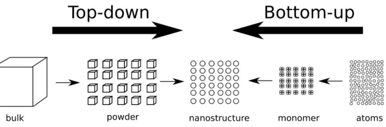
The optical properties of NPs depend strongly on their geometry and chemical composition which in turn also strongly depend on the synthesis method used. For NPs, the synthesis methods are generally grouped into either a “bottom-up” or a “top-down” route (Figure 2.2). The first subsection of this part contains several popular methods of noble metal NPs fabrication and the second subsection introduces the silica coating process on the metallic surface (mostly gold and silver) to construct the core-shell structure.
Figure 2.2 Schematics of top-down approaches and bottom-up approaches of nanomaterial synthesis.
Several gold-silver alloy nanoparticles synthesis methods have been introduced over the last decades. Dating back to 1976, Papavassilou[35] synthesized Au/Ag alloy NPs in colloidal solution through evaporating gold-silver alloy with different composition using a high-frequency electric bridge. In fact, Au/Ag alloy NPs are relatively hard to synthesize because of the existence of the phase separation at the atomic level, resulting in a preferable core-shell structure.[36] However, Papavassilou observed the extinction spectra of such NPs with only one resonance peak, indicating that gold and silver atoms were not in a core-shell structured phase separation. He also reported the linear correspondence of plasmonic peak position and chemical composition ratio (Au/Ag) of NPs.
In general, all synthesis of a material can be sorted into physical routes or chemical routes. In the case of Au/Ag alloy NPs synthesis, laser can be utilized to fabricate Au/Ag alloy NPs in both ways. For instance, the laser ablation can take place in a liquid medium where there is a target of Au/Ag alloy piece with a specified composition ratio. Similar to the method of evaporation used by Papavassilou, laser ablation is also a “top-down” approach, where the macroscopic material is broken down to NPs. Laser ablation method has been used by Lee and his coworkers[37] in liquid water with a Nd:YAG nanosecond laser at 1064nm. Since the optical energy delivered per unit area of the laser pulse is high enough to evaporate the alloy target, stoichiometric Au/Ag alloy NPs are formed with ejected atoms in the liquid.[38] Laser can also be used to assist a chemical route. For instance, Peng et al. [39] prepared Au/Ag alloy NPs with gold NPs in a solution of Ag+ ions by 532nm (or 355nm) laser irradiation. It is a “bottom-up” method, where the nanoparticles are formed originally from the separated atoms such as gold and silver ions.
Although the laser-ablation method is facile and synthesis is rapid, the laser-based set-up is not very available and alternative techniques have been considered, such as ultrasound[40], UV light[41], or simply heating. The essence of such chemical routes, apart from different irradiation approaches, is the same: mixed metallic component ions are reduced in the liquid simultaneously to form alloy NPs. The most frequently appearing reduction of gold and silver salts tetrachlorauric acid (HAuCl4) and
silver nitrate with a citrate acid. Link et al, among other pioneers, firstly used this co-reduction method to fabricate Au/Ag alloy NPs at 100℃.[42] Mallin et al conducted the sub-10nm Au/Ag alloy NPs synthesis at room temperature by using the reducing agent sodium borohydride (NaBH4). [43]
Since the chemical route is used throughout this master work, we now cover the mechanism of formation of monodispersed Au/Ag alloy NPs as an example. The silica coating of NP will be discussed later in section 2.2.
2.1.1 Mechanism of chemical synthesis route
The most widely used synthesis technique of NPs is the Turkevich method.[44, 45] For Au NPs, it involves the chemical reduction of HAuCl4 in a sodium citrate solution. Based on this method, Frens
and his coworkers[46] have investigated the synthesis of 16-150nm gold NPs and concluded that the ratio citrate/metal affects largely the magnitude of NPs size and the size distribution. To understand this better, let us look at the mechanism of NPs formation. In general, as shown in Figure 2.3 there are three phases for NPs synthesis following the chemical route:
1. The reduction of ions of gold and silver to form monomers. This will continue until there is little ions left for reduction. In the meantime, the concentration of monomers keeps increasing and cross a critical value when the nucleation takes place.
2. The nucleation happens when the concentration of monomers exceed the critical value. The speed of nucleation mostly depends on the concentration of monomer. With the consumption of the monomers during nucleation, the concentration of monomers drops again within the critical value.
3. The growth involves monomers adhering on the nuclei to form the NPs. Ideally, a clear separation in time of the nucleation and growth will result in a very fine size distribution (monodispersed) of NPs. However, nucleation might continue during growth resulting in some smaller nuclei and non-monodispersed NPs.
Figure 2.3 Schematics of 3 steps for the formation of NPs from metallic ions in solution. The metallic ions such as Au3+ are reduced to Au atom to form gold monomer dispersed in solution. The
monomers aggregate to form Au nuclei and they grow larger with monomers sticking on the nuclei surface.
Figure 2.4: LaMer diagram illustrating NPs formation steps.[47] Phase I, II and III correspond respectively to the reduction state, nucleation state and NPs growth in Figure 2.3. Copyright © 2013 Elsevier Inc. All rights reserved.
For most applications, it is preferable to have monodispersed NPs. We can use LaMer diagram shown in Figure 2.4 [48] to study how reaction conditions affect the NPs size and its distribution. The factors to modify conveniently are temperature and the concentration ratio of citrate and metallic ions (Cc/Cm). The former one, is usually fixed at 100℃. The discussion of Cc/Cm is as follows:
1. For a high Cc/Cm, the reducing rate is quite high and the concentration of monomer, in a short
time, results in a high supersaturation ratio S. Shown in Figure 2.4, supersaturation is defined as current concentration of solute over the saturated concentration. When S is significantly greater than the critical value (Sc in the Figure 2.4), nucleation occurs. A large quantity of nuclei are
quickly formed in this case, significantly reducing metallic ions or monomer concentration. The final sample contains many small NPs. Since the nucleation happens so fast, there is little time for growth during nucleation, thus resulting in monodispersed NPs formation with larger quantity but a smaller dimension.
2. For a small Cc/Cm, on the contrary, the low reducing rate will keep the supersaturation ratio
narrowly above Sc thus providing a low nucleation rate. In this case, the growth of nuclei happens
simultaneously with the generation of new nuclei. The early-generated nuclei result in larger NPs while the later-generated nuclei end up smaller, yielding to a polydispersity. Therefore, it is extremely hard to fabricate in a one-step synthesis relatively large nanoparticles with a narrow size distribution. Indeed, we need to have a relatively high concentration of gold and silver ions to be reduced in order to grow a larger nanoparticle, but restricted by the too low Cc/Cm to get large
and monodispersed NPs. Frequently, the solution to such problem is a multi-step synthesis. The next section covers a typical multi-step synthesis method named seed-mediated growth.
2.1.2 Seed-mediated growth
The seed-mediated growth is a “bottom-up” synthesis method that requires a proper concentration of seeds in the solution system so that the monomer formed through reduction can be easily grown onto their surface. Since the existing surface of the seed can provide the nucleation position with less surface energy, there is a better chance to nucleate onto the surface of seed when the concentration of monomers is low enough. Ideally, if all the monomers formed are on the surface of seeds equally distributed, the size of final NPs can be easily deduced according to the proportional relation between the volume of single nanoparticles and precursor ion numbers.
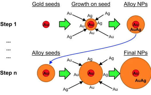
Gold and silver NPs with a large size ranging from tens to hundreds of nanometers were synthesized with seed-mediated growth method [49-52]. However, the monodispersed Au/Ag alloy NPs were recently obtained by Rioux et al [30] using the seed-mediated growth technique. In this case, the Au/Ag alloy NPs were fabricated from a gold seed of 13-15nm, and the precalculated Au3+/Ag+ ions
were added into a boiling water bath with citrate as reducing agent (see figure 2.5). Typically, the first growth step has a “Seeding Ratio (R)” of 10, which is defined as
of 28.0 nm-32.3 nm according to different sizes of gold seeds.
Subsequently, the as-prepared alloy NPs were used as “Seeds” to fabricate larger NPs. This process keeps the Cc/Cm to an appropriate value favoring growth rather than nucleation, resulting in a
relatively monodispersive large Au/Ag alloy NPs. The linear dependence of composition ratio between gold and silver were validated again.
Figure 2.5 Schematic of multi-step Au/Ag alloy NPs synthesis. A ~15nm gold seed is grown to be Au/Ag alloy NP with Au3+ and Ag+ ions reduced on the surface of seed. Greater size (up to 150nm)
alloy NPs are grown from smaller size alloy NPs.[30] Copyright © 2015, American Chemical Society
2.2 Synthesis of metallic core silica shell nanostructure
A core-shell nanostructure is composed of a core material and another material of shell, all at a nanoscale, which can be semiconductor-semiconductor, metal-semiconductor, metal-metal nanocomposite and so forth. The advantages of core-shell structures are frequently pertinent to
different properties of each component of the structure, such as the adjustment of surface properties, modification of surface charging and surface functionalization, which can increase the stability of the nanocomposite in complex media[53-55]. In addition, these core-shell structures could also show advantages of multifunctional physical properties, such as combination of optical[56-58], catalytic[59-63] and magnetic properties[7, 59, 64]. Accordingly, core-shell nanocomposite has been applied as devices in various fields, such as biomedical, chemistry, electronics, etc [65].
Plasmonic nanoparticles, such as gold, silver and Au/Ag alloy, are of great significance of being the core of a core-shell structure. The excellent plasmonic properties of noble metal nanoparticles can be further exploited when embedded in the oxide layer to have surface modification. Typically, for Ag@SiO2, Au@SiO2, we can choose a surface chemistry to tailor the dielectric and optical properties by adjusting the thickness and coating or doping materials [66-68]. The advantages of coating a silica shell onto plasmonic nanoparticles are to provide not only a stabilizer on the surface, which prevent severe aggregation, but also a stable optical spacer for its property being chemically inert and optically transparent.[69] In this section, some common synthesis methods such as sol-gel, reverse micelles are reviewed to fabricate Ag@SiO2, Au@SiO2 and other similar core-shell nanostructures.
2.2.1 Sol-gel
As a well-applied synthesis method for inorganic material, sol-gel process is well-known for its mild conditions (temperature and pH) to fabricate nanomaterials with high-level homogeneity and purity[70]. This process is based on the hydrolysis of metal alkoxide and afterward condensation in an acidic or basic environment. Stöber process, as regarded as the pioneering work for the synthesis of monodispersed silica particles (see Figure 2.6), is a typical sol-gel process that can also be used to produce silica shell coating. It involves hydrolysis of tetraethyl orthosilicate (TEOS, Si(OC2H5)4) for coating an uniform layer onto the nanoparticles while the silica sols are used to induce condensation of TEOS and nucleation of silica monomer near the surface of metallic nanoparticles to form conformal silica shell. The typical thickness can be controlled from several to hundreds of nanometers by hydrolysis and condensation reaction of the alkoxide, for example TEOS, which is very useful and has been mentioned in numerous papers[71].
Figure 2.6 The hydrolysis and polycondensation reaction routes of TEOS. (a) Hydrolysis of TEOS to generate Si(OH)4; (b) dehydrated condensation of Si(OH)4 to form SiO2 matrix.[72] Copyright © 2015 The Institution of Chemical Engineers. Published by Elsevier B.V. All rights reserved.
Figure 2.7 Schematic representation of the SiO2 shell growth mechanism on Ag core. The formation of core-free SiO2 happens when the concentration of silica precursor (TEOS) or the hydrolysis rate is too high, resulting in the nucleation of SiO2 taking place not on the surface of silver NPs.[73]Copyright © 2015 Elsevier Inc. All rights reserved.
It is important to control the morphology of the silica matrix during the synthesis in order to fabricate fibres, thin films or nanoparticles. Factors, such as the concentration of silica precursor, water and acid or base, could influence the silica growth process having different morphologies. During silica shell coating on the surface of metallic nanoparticles, for instance, silver nanoparticles, different experimental conditions can result in various groups of products such as core-free silica nanoparticles and multicore nanoparticles. Since the alkoxysilane has a poor
miscibility with water but not alcoholic solvents, it was found that ethanol, methanol or isopropanol needed to be involved in the synthesis[74]. In fact, the type of solvent is also a factor that affects the silica shell formation. Since silica precursor hydrolysis rates and the tendency for metallic nanoparticles to aggregate are different in each solvent, the selection of the solvent is vital. For Ag@SiO2 nanoparticles synthesis, the effect of alcoholic solvents has been systematically studied by Niitsoo et al[75]:
1. In methanol, with the comparatively higher hydrolysis rate, the possibility of appearance of SiO2 core-free nanoparticles is higher and some of the silver nanoparticles may remain uncoated.
2. In ethanol on the other hand, where the hydrolysis of the silica precursor is not as high as in methanol, the core-free nanoparticles appear only if the surface area of silver nanoparticles are not sufficient for silica nucleation. Therefore the ratio of Ag/TEOS plays an important role in terms of silica nanoparticle formation. Shown in Figure 2.7, the Ag core-free nanoparticles are formed as the Ag surface does not have enough position for SiO2 nucleus. 3. In 2-propanol, only the Ag@SiO2 nanoparticles are formed but multicore nanoparticles
(several Ag nanoparticles are enclosed in silica shell) also exist in the products.
As for the effect of catalyst, the acidic conditions (HCl for example) and basic conditions (ammonia for example), with different catalyzing mechanism, generate different form of condensed silica. Buckley[76] reported that slower hydrolysis occurred under acidic conditions where silica chains are formed preferably while faster hydrolysis was involved with higher pH where more clusters were formed as discrete species. Indeed, the rate of the hydrolysis is largely affected by the radius of negative ions[77]. Under the basic conditions, OH- ions directly attack the silicon nuclei, resulting in a higher hydrolysis rate and it can be regarded that the whole condensation process begins after the finish of hydrolysis. The similar situation takes place under acidic condition when more water is added in the system so that the hydrolysis rate increases while condensation rate decreases due to the lower precursor concentration.
Taken into account the influence of catalyst on the metallic core, silver nanoparticles are affected by both HCl and ammonia. The Cl- can attack the silver core to cause the etching effect and the similar process has been used with the addition of NaCl in Ag@SiO2 to intentionally etch silver core in order to fabricate hollow silica shell[25, 78]. The etching mechanism of
ammonia-On the other hand, coating silica onto gold nanoparticles is more challenging compared to the case of silver cores. The main problem is the stability of the colloidal solution in organic solvent, methanol or ethanol for instance. During the preparation of gold nanoparticles, it is well known that the citrate ions are finally attached to the surface of NPs as a stabilizer. However, in an organic solvent, the citrate amount is insufficient to stabilize the nanoparticles and they agglomerate within seconds to minutes[79].
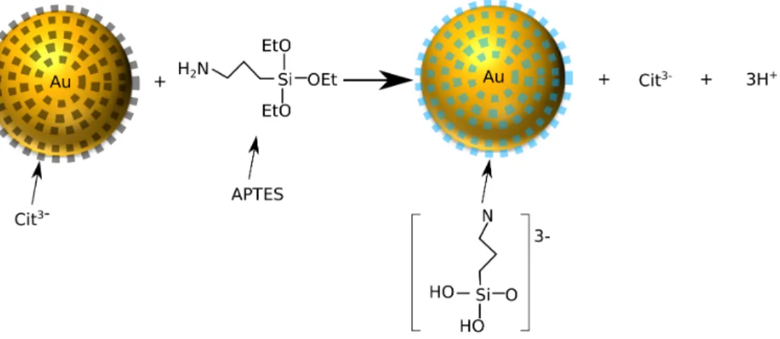
The synthesis of Au@SiO2 can be accomplished through a sol-gel process by using a silica precursor such as TEOS or sodium silicate, after a premier surface activation (shown in figure 2.6) with, typically, aminopropyl triethoxysilane (APTES)[69], followed by a dehydration condensation of TEOS on the colloid surface to form a silica layer. As shown in the schematic (figure 2.6), APTES, a silane coupling agent surface primer, plays a role of transferring citrate stabilized gold surface from vitriophobic to vitriophilic[80], which enables the further Stöber process. The citrate ions are replaced by APTES due to a strong adsorption of amine on the gold colloid surface. The hydrolysis of these APTES occurs to render silane triols which stabilize the gold colloid with ionized silane triols that are negatively charged[69].
Figure 2.8 Schematics for surface primer attachment to citrate-stabilized gold colloid for further silica coating. The figure does not show the number of primer on the surface of Au NP.
Liu and Han[79] have also introduced a method to increase the citrate concentration on the surface of gold nanoparticles in order to transfer the gold nanoparticles into organic solvent for silica coating. In this case, the extra citrate has been added to the boiling gold colloid solution and cool down so that more citrate ions are on the surface of gold. Then, it can be safely transferred for subsequent silica coating.
2.2.2 Reverse Micelles
A micelle is an assembly of amphiphilic molecules (surfactant molecules) in equilibrium with a surrounding solvent and dispersed in the solution. Typically, the particle-shaped micelles gather together with a hydrophobic tail towards the center while hydrophilic head sticks to the surface. Reverse micelles, on the other hand, are water droplets with tunable size dispersed in continuous organic solution automatically enclosed by surfactants. The polar side of the surfactant is hydrophilic and soluble in water, which turns into the droplet while the apolar side stays in contact with the organic solvent.[81] The frequently used surfactants include Cetrimonium bromide (CTAB)[82], Dioctyl sodium sulfosuccinate(Aerosol-OT or AOT)[83]. The microemulsion solution (water-in-oil) can be prepared to template nanoparticles to be fabricated with the help of the surfactant. Hybrid nanoparticle synthesis can also be conducted by using the reverse micelle method. The main advantage of this method is to delicately control the silica nucleation and polymerization inside the droplets of the reverse micelle.[84]
Tuo Li and coworkers reported a synthesis method of Ag@SiO2 nanoparticles by using reverse micelle and sol-gel processing, where the microemulsion with TEOS hydrolysis and condensation rate control the size of particles and thickness of silica shell[83]. Typically, the coating of in situ synthesized nanocrystal, such as Ag NPs, begins with the reduction Ag+ ions in the reverse micelles to firstly form Ag NPs. TEOS with base is subsequently added to lead the sol-gel process so that SiO2 shell can be coated onto the Ag NPs due to hydrolysis and condensation of TEOS. The microemulsion keeps NPs separated instead of aggregating. Igepal CO-520 was used in Li’s experiment as surfactant. The molar ratio of water to TEOS was studied to determine the thickness of the silica shell while the ratio of water/surfactant was also an important factor to control the resulting size of the NPs. Yang and Holloway[85] have also shown that QDs could also be coated with silica shell in the microemulsion. More recently, Huang Lu
2.2.3 Summary
Both sol-gel process and reverse micelle method are facile, inexpensive and controllable method to perform the synthesis of metal@SiO2 hybrid nanoparticles. By sol-gel process, high purity and homogeneous chemical properties can be obtained whereas some clustered products may exist. By the reverse micelle method, the small radius can be controlled through the size of water-in-oil microemulsion by adjusting the water/oil (W/O) ratio. It can be applied to coating on pre-synthesized nanocrystals as well as in situ pre-synthesized nanocrystals such as Ag, Au, Fe2O3, quantum dots, etc. For unstable nanoparticles in water/ethanol/TEOS mixture, the latter method is more popular. However, the microemulsion formation requires plenty of surfactants, which can raise more issues of factors such as pH, temperature and its concentration that affect the stability of microemulsion.
2.3 Surface plasmonic effect
Plasmons are collective excitation of electrons in a solid irradiated by an electromagnetic field. Surface plasmonic effect happens when an electromagnetic field interacts with free electrons at the surface of a metal. Among metals, the noble metals, such as gold, silver, copper, etc, have outstanding plasmonics properties, which attracted more attention as materials to be studied and used in various applications, including in medicine and biology.
2.3.1 Localized surface plasmon resonance (LSPR)
When the surface plasmon is confined in a metallic nanoparticle in three dimensions, it is called a localized surface plasmon and under a resonance, it is called a localized surface plasmon resonance or LSPR. The frequency of the oscillation depends mainly on the composition, size and geometry of the nanomaterial as well as the medium. When the size of nanoparticles is small enough comparing to the incident wavelength (d<20nm[87, 88]), the incident field exerted on NP
can be considered as a constant and can be approximately regarded as a dipole where the free electrons of the particle are polarized with the wave front of the light[89]. However, when the size of nanoparticles is not small enough to consider a constant electric field over the particle, we cannot apply the dipolar approximation whereas one side of the particle can be charged both positively and negatively so that it should be characterized more properly as multipole. In this project the NPs used are larger than 60nm, therefore Mie theory[87] must be applied.
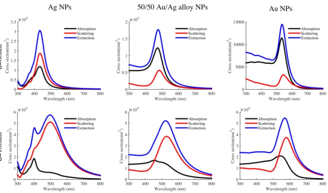
Figure 2.9 Absorption, scattering and extinction spectra of Ag, 50/50 Au/Ag alloy and Au NP with diameter 60nm (top row) and diameter 100nm (bottom row). Water is the medium. Figure is produced based on Mie theory[87] and dielectric functions of Au/Ag alloy NPs giving in [90]. Figure 2.9 shows the absorption, scattering and extinction calculated cross sections of plasmonics NPs having two different sizes (diameter 60nm and diameter 100nm) and three different compositions (Ag, 50/50 Au/Ag and Au) in water. The calculations are based on Mie theory[87] and dielectric functions of Au, Ag and Au/Ag alloy NPs are obtained from Rioux et al[90]. Note that for smaller 60nm alloy and Au NPs, the absorption overweighs the scattering while the full width at half maximum (FWHM) of scattering spectrum of 60nm NPs is smaller than the one of 100nm. However, from Figure 2.9 we can see that for the same size, the scattering cross section of Ag is higher than absorption, showing a stronger LSPR property. Actually, for multiplexed
Figure 2.10 UV-visible spectra of 60nm gold, silver and alloy NPs with Au/Ag ratios 20/80, 40/60, 60/40 and 80/20. All spectra were normalised to 1.0. Figure is produced based on Mie theory[87] and dielectric functions of Au/Ag alloy NPs from [90].
The conductive band structure of NP also plays a role in determining the plasmonic peak position. For Au/Ag alloy NPs with different composition, the extinction spectra peaks vary from blue to green, for example for 60nm Ag to 60nm Au: from 433nm to 535nm as calculated by Mie theory[87] (Figure 2.10).
As discussed above, the plasmonic NP can absorb light and scatter it strongly. The optical cross section of the NP could be in some cases larger than the physical cross section. For example 60nm Ag, 50/50 Au/Ag alloy and Au NPs (Figure 2.9) have respectively scattering cross-sections 6.6, 2.0, 1.1 times larger than their actual physical cross sections at resonance. With the incident electric field, the oscillation of free electrons also generates a polarized electric near-field enhancement[87, 91], as shown in Figure 2.11. This field enhancement is affected by the NP size, the composition, the geometry and the wavelength and polarisation of incident light. In this figure, we can see that 80nm Au/Ag alloy NP shows more asymmetrical field enhancement, which indicates that multipolar effect is playing a role due to the relative scale ratio between NP and
wavelength. The field enhancement can be more than 5 times and the intensity accordingly can be enhanced more than 25 times depending on the position near the NP. This near field enhancement may be used in some applications such as surface enhanced fluorescence (SEF) or surface enhanced Raman spectroscopy (SERS), which will be briefly introduce later.
Figure 2.11 Near electric field enhancement under an irradiation of a linearly polarised 514nm wavelength light for (a) 60nm Ag NP and (b) 80nm 50/50 Au/Ag NP.
2.3.2 Metal enhanced fluorescence (MEF)
Fluorescent molecules (or fluorophores), when exited by a light near their maximum excitation wavelength, can re-emit light by photoluminescence near their maximum emission wavelength. It is vastly used as biomarker or dye in imaging. The metal enhanced fluorescence (MEF), in short, is the fluorescent intensity as well as photostability enhancement of a fluorophore near a metallic surface. Before going into details, the basic concepts for fluorescence need to be reviewed.
The maximum excitation and emission wavelength corresponds to the position of excitation peak and emission peak. The quantum yield, describing the efficiency of the energy transferred from incident light to emission of fluorescence, is defined as Q = Γ (Γ + Γ!"), where Γ is the emission
rate of electrons at first excited state after being excited by the incident light and Γ!" denotes the non-radiative decay rate of the electrons to the ground state. The lifetime refers to the time during which the electrons stay in the excited state, defined as 𝜏 = 1 (Γ + Γ!").
Figure 2.12 Jablonski diagram of fluorescence excitation and emission when the fluorophore is in free space and near a metallic NP. The enhanced field near the metallic NP surface is shown at the right top of the schematics.
Near a plasmonic nanoparticle surface, the field enhancement can be felt by the fluorophore, resulting in an increase of the emission intensity. In fact, the plasmonic nanoparticle can manipulate light below the diffraction limit[92] by concentrating it at near-field as a “nanolens”. Moreover, the presence of the metal surface can induce an increase of the radiative rate of nearby fluorophore thus providing a shorter lifetime and greater quantum yield, which leads to a larger fluorescent intensity[27]. In this case an increase of photonic mode density enhances the radiative decay pathways due to the existence of the metal as shown in schematically in Figure 2.12. In this case, the emission rate Γ of the fluorophore is modified as (Γ + Γ!), where Γ! corresponds to the emission rate increase in the presence of the metal. [93] The quantum yield and lifetime become:
𝑄 =Γ + ΓΓ + Γ!
𝜏 =Γ + Γ1
!+ Γ!"
From the equations, one can see that the metal enhancement (Γ!) becomes important on Q when the non-radiative decay (Γ!") is relatively large. However, we must consider the local distribution of the fluorophores near the plasmonic NP surface. Frequently, a fluorophore is considered as a dipole model, and its orientation plays a role in the emission intensity. When the fluorophore is located near the polarized field maximum, its dipole can be enhanced to be further excited and emit more photons. The distance between the metal surface and fluorophore is also important for the fluorescent rate[94]. If the distance between the metallic surface and the fluorophore is RF, and assuming a dipole-dipole interaction, then the non-radiative decay rate is proportional to RF6 but only valid when RF≥ 𝑟!"/10. In fact, if the molecule is too close to or even attached to the
metallic surface, there is a much higher non-radiative energy transfer from the molecule to metal and the fluorophore is quenched by the metal.[95]
The core-shell structure with a metallic core is very convenient for MEF effect, for the vicinity of fluorescent molecule doped in silica shell all over metallic nanoparticle. It is reported that silver colloid surfaces have yielded up to 50-fold enhancement[96]. The similar magnitude of fluorescence enhancement factor was also obtained with a gold core. This factor was calculated by obtaining the ratio of fluorescence intensity between fluorescent core-shell NPs and core-free NPs[78].
Figure 2.13 Nearfield enhancement of 60nm Ag NPs, Au NPs and 50/50 Au/Ag alloy NPs as a function of wavelength.. Calculation with dielectric function of Au/Ag alloy in water[90].
Since it is possible to control the plasmonic resonance peak wavelength for gold-silver alloy NPs according to their Au/Ag composition ratio, it is also possible to design the NPs that would fit the excitation or emission wavelengths of fluorescent molecules so that the fluorescent intensity could be even more amplified. Figure 2.13 shows the near-field enhancement as a function of the incident wavelength and can be used to determine the choice of flurophore and irradiation conditions. Some typical studies of other conditions with plasmonic-based nanostructure and different fluorophores are shown in Table 2.1.
Table 2.1 Pertinent studies of MEF in literature with different conditions.
Material and geometry Dimension Fluorophore Enhancement factor reference
Au NP 40nm FITC 1.75 [97] 200nm 2.5 14nm TAMRA-SE−PLL 9.2 [98] 50nm IR800 40 [99] Au nanorod 80×13nm Cyanine 5 7.6 [100] 46×11nm IR800 9 [99]
Ag nanoprism 100nm edges Alexa Fluor 488 9-30 [101]
Ag NP 75nm FITC 12.5 [102] 40nm Alexa Fluor 350 (AL350), FITC, pacific blue (PB),
Alexa Fluor 514 (AL514), Rhodamine 6G (Rh6G), Alexa Fluor 647 (AL647), Alexa Fluor 680 (AL680)
2-17
[34]
incident light, as shown in Figure 2.14. The index 4 comes from the field enhancement by both excitation and emission, which normally generates an enhancement factor of 104-106[104]. The application of plasmonic NP, especially gold and silver NP, for SERS application is a hot research topic. [29, 105] In fact, a SERS enhancement factor of ~107 is sufficient for single molecule detection[106]. Moreover, by modifying the structure of plasmonic material, namely with optimized geometry, the field enhancement can be further increased. For instance, dimers of silver spheres increase an addition 100-1000 fold of enhancement of Raman signal if the molecule is positioned between two closed nanospheres.[107]
Figure 2.14 Schematic showing the surface enhanced Raman spectroscopy by Ag NP. A molecule near the surface of Ag NP has greater Raman signal (orange) due to electric field enhancement than the one away from enhanced field (blue).
2.4 Bioimaging with plasmonic nanostructures
Contrast agents in bioimaging are necessary tools for biologists and pathologists. The existing optical bioimaging contrast agents for cell labeling are fluorescent molecules, QDs, plasmonic NPs, etc. Actually, there is a tremendous effort in the development of multiplexed imaging with different types of multicolor labellers to enhance the efficiency of differentiating cellular phenotypes. Therefore, in this section, we discuss various contrast biomarker agents and introduce some examples of multiplexed bioimaging techniques.
2.4.1 Contrast agents for cell imaging
In a general manner, there are two ways of targeting cells or organs for bioimaging applications. The first one, more complicated, involves genetics modification and the production of fluorescent protein such as the well-known green fluorescent protein[108] for which Doctor Tsien received the Nobel price. The second one, much more straightforward, uses fluorescent monoclonal antibodies and their ability to link specifically to their corresponding cell antigens, which is called immunofluorescence. Although fluorescent monoclonal antibodies are very useful, it has some significant drawbacks. First, they are costly and are very limited in choices of fluorescence types, especially for ones with high quantum yield. Besides, the fluorophores are vulnerable to photobleaching, which makes it very difficult to restudy the same cells from one region after a certain observation time with high exposure from the optical set-up. Moreover, due to the two drawbacks above, when targeting to the antigens with less specificity, the intensity of the fluorescent label and the observation time can be both limiting. QDs[17-20] as one of the promising alternatives show better photostability and were also applied in bioimaging applications. QDs of different compositions exhibit highly defined luminescence when excited in UV region [18]. However, the toxicity of the semiconductor material and the intermittence of the emission signal, referred to as “blinking”, limit the application to cell imaging.
On the other hand, plasmonic nanocrystals such as gold and silver NPs also offer interesting properties for bioimaging, namely high scattering bands under dark-field (DF) microscope mode, absence of blinking and photobleaching. Au NPs are furthermore chemical inert and less toxic with cells. With the technique of surface modification and functionalization with monoclonal antibodies, NPs are able to be used as specific cell labeller, named immunoplasmonics[109]. The
And for standard darkfield imaging, plasmonic NPs are required to be large enough to scatter sufficient light to be seen under the optical microscope, which increase the difficulty of synthesis. Fortunately, surface modification can be done with plasmonic NPs to increase their stability inside a complex medium. Polyethylene glycol (PEG) and Polyvinylpyrrolidone(PVP) are two frequently used polymers to modify the NP surface so that the precharged NP surface cannot be absorbed to cell surface easily or due to the hindrance of the polymer on surface the NPs tend not to aggregates easily[111]. In Table 2.2, typical candidates for contrast agents are listed and compared.
Table 2.2 Typical contrast agents in bioimaging.
Contrast agents Advantages Disadvantages References
Fluorophore
(immunofluorescence)
Mature and widely used, standard
methods for
examination
Low intensity, photobleaching, complexed procedure with indirect immunofluorescence, spectral overlapping [112-114] QDs Defined peaks, uniform exitation Blinking, toxicity [17, 18, 20] Ag NPs Strongest scattering signal, plasmonic properties
Toxicity, low chemical stability, resonance in blue so that difficult for signal collection and in vivo application [115-117] Au NPs Strong scattering signal, plasmonic properties, biocompatibility
Broad plasmonic band, resonance in green and yellow so that difficult for in vivo application, heat generation with high absorption [13, 24, 26, 28, 118, 119] Au nanorod Near-infrared emission, in vivo application
Complex synthesis control,
two plasmonic peaks, broad spectra
[23, 118-121]
Hybrid structure (core-shell)
Flexible properties for different applications, e.g. Au shell for near-infrared emission
Complexed synthesis control, optical property highly sensitive to structure
[6, 122-124]

![Figure 2.4: LaMer diagram illustrating NPs formation steps.[47] Phase I, II and III correspond respectively to the reduction state, nucleation state and NPs growth in Figure 2.3](https://thumb-eu.123doks.com/thumbv2/123doknet/2350581.36168/28.918.110.584.512.846/figure-diagram-illustrating-formation-correspond-respectively-reduction-nucleation.webp)
![Figure 2.6 The hydrolysis and polycondensation reaction routes of TEOS. (a) Hydrolysis of TEOS to generate Si(OH) 4 ; (b) dehydrated condensation of Si(OH) 4 to form SiO 2 matrix.[72] Copyright © 2015 The Institution of Chemical](https://thumb-eu.123doks.com/thumbv2/123doknet/2350581.36168/32.918.115.755.106.387/hydrolysis-polycondensation-hydrolysis-dehydrated-condensation-copyright-institution-chemical.webp)