HAL Id: tel-01416336
https://hal.archives-ouvertes.fr/tel-01416336v2
Submitted on 17 Jan 2017HAL is a multi-disciplinary open access archive for the deposit and dissemination of sci-entific research documents, whether they are pub-lished or not. The documents may come from teaching and research institutions in France or abroad, or from public or private research centers.
L’archive ouverte pluridisciplinaire HAL, est destinée au dépôt et à la diffusion de documents scientifiques de niveau recherche, publiés ou non, émanant des établissements d’enseignement et de recherche français ou étrangers, des laboratoires publics ou privés.
Heloi Francico Gentil Genari
To cite this version:
Heloi Francico Gentil Genari. Damage-Tolerant Modal Control Methods for Flexible Structures. Automatic. Ecole nationale supérieure d’arts et métiers - ENSAM; Universidade estadual de Campinas (Brésil), 2016. English. �NNT : 2016ENAM0032�. �tel-01416336v2�
HELÓI FRANCISCO GENTIL GENARI
Damage-Tolerant Modal Control Methods for
Flexible Structures
Métodos de Controle Modal Tolerante a
Danos para Estruturas Flexíveis
CAMPINAS 2016
Damage-Tolerant Modal Control Methods for
Flexible Structures
Métodos de Controle Modal Tolerante a
Danos para Estruturas Flexíveis
Thesis presented to the School of Mechanical Engineering of the University of Campinas in partial fulfillment of the requirements for the degree of Doctor in Mechanical Engineering in the area of Solid Mechanics and Mechanics Design and under the joint supervision agreement signed between UNICAMP and Arts et Métiers ParisTech.
Tese de Doutorado apresentada à Faculdade de Engenharia Mecânica da Universidade Estadual de Campinas como parte dos requisitos exigidos para obtenção do título de Doutor em Engenharia Mecânica na Área de Mecânica dos Sólidos e Projeto Mecânico no âmbito do acordo de cotutela firmado entre a UNICAMP e a Arts et Métiers ParisTech.
Orientador: Prof. Dr. Eurípedes Guilherme de Oliveira Nóbrega e Prof. Dr. Nazih Mechbal Coorientador: Prof. Dr. Gérard Maurice Henri Coffignal
ESTE EXEMPLAR CORRESPONDE À VER-SÃO FINAL DA TESE DEFENDIDA PELO ALUNO HELÓI FRANCISCO GENTIL GENARI E ORIENTADO PELO PROF. DR. EURÍPEDES GUILHERME DE OLIVEIRA NÓBREGA E PELO PROF. DR. NAZIH MECHBAL.
... ASSINATURA DO ORIENTADOR
CAMPINAS 2016
Universidade Estadual de Campinas Biblioteca da Área de Engenharia e Arquitetura
Luciana Pietrosanto Milla - CRB 8/8129
Genari, Helói Francisco Gentil,
1985-G285d Damage-tolerant modal control methods for flexible
structures / Helói Francisco Gentil Genari – Campinas, SP: [s.n.], 2016.
Orientadores: Eurípedes Guilherme de Oliveira Nóbrega e Nazih Mechbal.
Coorientador: Gérard Maurice Henri Coffignal.
Tese (doutorado) – Universidade Estadual de Campinas, Faculdade de Engenharia Mecânica.
1. Vibração - controle. 2. Controle robusto. 3. Controle H [Infinito]. 4. Danos. 5. Estruturas flexíveis. I. Nóbrega, Eurípedes Guilherme de Oliveira, 1950-. II. Mechbal, Nazih. III. Coffignal, Gérard Maurice Henri. IV. Univer-sidade Estadual de Campinas. Faculdade de Engenharia Mecânica. V. Título.
Informações para Biblioteca Digital
Título em outro idioma: Métodos de controle modal tolerante a danos para estruturas flexíveis
Palavras-chave em inglês: Vibration control; robust control; adaptive control systems; damage tolerance; struc-tural health monitoring.
Área de concentração: Mecânica dos Sólidos e Projeto Mecânico
Titulação: Doutor em Engenharia Mecânica
Banca examinadora: Eurípedes Guilherme de Oliveira Nóbrega
[Orientador], Nazih Mechbal [Orientador], Volnei Tita, José Roberto de França Ar-ruda, Pedro Luis Dias Peres e Valérie Budinger.
Data da defesa: 15/09/2016
COMISSÃO DE PÓS-GRADUAÇÃO EM ENGENHARIA MECÂNICA
DEPARTAMENTO DE MECÂNICA COMPUTACIONAL
TESE DE DOUTORADO
Damage-Tolerant Modal Control Methods for
Flexible Structures
Métodos de Controle Modal Tolerante a
Danos para Estruturas Flexíveis
Autor: Helói Francisco Gentil Genari
Orientador: Prof. Dr. Eurípedes Guilherme de Oliveira Nóbrega e Prof. Dr. Nazih Mechbal Coorientador: Prof. Dr. Gérard Maurice Henri Coffignal
A Banca Examinadora composta pelos membros abaixo aprovou esta Tese: Profa. Dra. Valérie Budinger
DCAS, ISAE SUPAERO, França Prof. Dr. Volnei Tita
GEA, EESC/USP, Brasil
Prof. Dr. José Roberto de França Arruda DMC, FEM/UNICAMP, Brasil
Prof. Dr. Pedro Luis Dias Peres DSE, FEEC/UNICAMP, Brasil
Prof. Dr. Eurípedes Guilherme de Oliveira Nóbrega DMC, FEM/UNICAMP, Brasil
Prof. Dr. Nazih Mechbal
PIMM, Arts et Métiers ParisTech, França
A Ata da defesa com as respectivas assinaturas dos membros encontra-se no processo de vida acadêmica do aluno.
First, I would like to express my deepest gratitude to Prof. Dr. Eurípedes Guilherme de Oliveira Nóbrega, Prof. Dr. Nazih Mechbal, and Prof. Dr. Gérard Coffignal for their great su-pervision, friendly guidance, and encouragement throughout this study.
I am indebted to my family and my girlfriend for their endless love, care, and encourage-ment.
I wish to acknowledge the Department of Computational Mechanics and School of Mech-anical Engineering of UNICAMP and the Laboratory of Process and Engineering in Mechanics and Materials of Arts et Métiers ParisTech to provide an excellent infrastructure to carry out my research.
I would also like to thank Prof. Dr. José Roberto de França Arruda, Prof. Dr. André Ri-cardo Fioravanti, and Prof. Dra. Grace S. Deaecto for their willing help and multiple suggestions for my research.
I wish to acknowledge the Prof. Dr. José Roberto de França Arruda, Profa. Dra. Valérie Budinger, Prof. Dr. Volnei Tita, Prof. Dr. Jean-Christophe Ponsart, and Prof. Dr. Pedro Luis Dias Peres to participate of the jury.
My sincere thanks to all my friends at UNICAMP and at Arts et Métiers ParisTech for their help, understanding, and motivations throughout this work.
I wish to acknowledge CNPQ (“Bolsista CNPq - Proc. n◦ 141621/2012-5”) and CAPES
(“Bolsista da CAPES - Proc. n◦12337/13-7”) for my national and international research
O correr da vida embrulha tudo, a vida é assim: Esquenta e esfria, aperta e daí afrouxa, Sossega e depois desinquieta. O que ela quer da gente é coragem." (João Guimarães Rosa)
Smart structures have increasingly become present in different industry applications and particularly in the fields of aeronautics and civil engineering. These structures have features that allow interactions with the environment, adapting their characteristics according to the needs (stiffness, damping, viscosity, etc.), monitoring their health or controlling their vibra-tions. Today, smart structure active control methods do not respond appropriately to damage, despite the capability of good rejection of external disturbances. Damage-tolerant active control (DTAC) is a recent research area that aims to develop integrated approaches to reduce vibrations while monitoring the structure integrity, identifying damage occurrence, and reconfiguring the control law of the adopted active vibration control method.
This thesis contributes to the DTAC area by proposing a novel modal control framework and some application strategies. The developed methods focus on noncollocated flexible tures, where multiple piezoelectric sensors and actuators are used to attenuate damaged struc-ture vibration. The chapters present four main topics and the conclusions. Chapter 2 reviews the
regular suboptimalH∞problem and its respective solution based on the linear matrix
inequal-ity approach, which is a fundamental tool for the development of subsequent topics. Chapter 3
introduces the modalH∞-norm-based method for vibration control, which reveals high modal
selectivity, allowing control energy concentration on damage effects and presenting robustness to spillover and parameter variation. A new control strategy is developed in Chapter 4, tak-ing into account existtak-ing knowledge about the structure stressed regions with high probability
of damage occurrence, leading to specific requirements in the modalH∞-controller design. A
structural health monitoring (SHM) technique assesses each damaged mode behaviour, which is used to design a preventive controller. Chapter 5 presents a novel modal double-loop con-trol methodology to deal with the unpredictability of damage, nevertheless ensuring a good compromise between robustness and performance to both healthy and damaged structures. For this purpose, the first-loop modal controller is designed to comply with regular requirements for the healthy structure behaviour and the second-loop controller is reconfigured aiming to ensure satisfactory performance and robustness when and if damage occurs, based on a state observer and an SHM technique to adapt the controller online. In all these chapters, simulated (analytical- and finite-element-based) and/or experimental smart structures are used to examine the proposed methodology under the respective control strategies. The last chapter summarises
Keywords: Vibration control; robust control; adaptive control systems; damage tolerance;
Estruturas inteligentes estão cada vez mais presentes em diferentes aplicações na in-dústria, em particular nas áreas de aeronáutica e engenharia civil. Essas estruturas possuem características que permitem interações com o ambiente, adaptando suas propriedades de acordo com as necessidades (rigidez, amortecimento, viscosidade, etc.), monitorando a própria integ-ridade estrutural (SHM, de Structural Health Monitoring) ou controlando suas vibrações. Atual-mente, os métodos ativos para controle de vibrações não respondem adequadamente a mudanças na dinâmica estrutural causada por dano, apesar da boa capacidade de rejeição a perturbações externas. O controle ativo tolerante a danos (DTAC, de Damage-Tolerant Active Control) é uma área recente de pesquisa que objetiva desenvolver métodos integrados para reduzir vibrações e, ao mesmo tempo, monitorar a integridade estrutural, sendo possível identificar a ocorrência de danos e, com isso, reconfigurar o controlador ativo de vibrações.
Esta tese contribui com a área de DTAC propondo uma nova abordagem de controle modal e algumas estratégias de aplicações. Os métodos propostos focam no controle de vibrações de estruturas flexíveis sujeitas a danos com múltiplos sensores e atuadores não colocados. Os capítulos apresentam quatro temas principais e as conclusões. O Capítulo 2 revisa o problema
subótimo H∞ e sua respectiva solução por meio da abordagem por desigualdades matriciais
lineares, que é uma ferramenta fundamental para o desenvolvimento dos tópicos subsequentes.
O Capítulo 3 introduz o método de controle modal de vibrações baseado na normaH∞modal, a
qual revela elevada seletividade modal, permitindo a concentração de energia de controle sobre os efeitos do dano e apresentando robustez em relação ao spillover e à variação paramétrica. Uma nova estratégia de controle é desenvolvida no Capítulo 4, tendo em conta o conhecimento existente sobre as regiões da estrutura com alta probabilidade de sofrer danos, o que leva a
re-quisitos específicos no projeto do controladorH∞modal. Uma técnica de SHM é usada para
avaliar o efeito do dano em cada modo, dado que é usado para projetar um controlador pre-ventivo. O Capítulo 5 apresenta uma metodologia modal de dupla malha que lida com a im-previsibilidade do dano, garantindo um bom compromisso entre robustez e desempenho para a estrutura saudável ou danificada. Para atingir esse objetivo, o controlador modal da primeira malha é projetado para atender os requisitos de desempenho para a estrutura íntegra. O con-trolador da segunda malha é reconfigurado objetivando assegurar robustez e um desempenho satisfatório quando, ou se, um dano ocorre. Essa lei de controle é baseada em um observador
resultados obtidos para cada abordagem descrita nos capítulos anteriores.
Palavras-chave: Vibração - controle; controle robusto; controle H [Infinito]; danos; estruturas
Les structures intelligentes sont de plus en plus présentes dans différentes industries et notamment dans les domaines de l’aéronautique et du génie civil. Ces structures sont dotées de fonctions qui leur permettent d’interagir avec leur environnement, d’adapter leurs cara-ctéristiques structurelles (raideur, amortissement, viscosité, etc.) selon les besoins ou de sur-veiller leur état de santé ou SHM (Structural Health Monitoring). Aujourd’hui, les performances des méthodes de contrôle actif peuvent être considérablement dégradées lors de l’apparition d’endommagement. Le contrôle actif tolérant aux dommages ou DTAC (Damage-Tolerant Act-ive Control) est un champ de recherche récent qui s’intéresse à l’élaboration d’approches inté-grées pour réduire les vibrations tout en surveillant l’intégrité de la structure, en identifiant les éventuels dommages, et en reconfigurant la loi de commande.
Cette thèse apporte une contribution au DTAC en proposant une approche originale basée
sur la normeH∞ modale. Les méthodes proposées se focalisent principalement sur le cas où
plusieurs actionneurs et capteurs piézoélectriques non-collocalisés sont utilisés pour atténuer les vibrations des structures endommagées. Le manuscrit comprend quatre parties principales.
Le chapitre 2 présente des rappels sur la commandeH∞et sur sa solution sous optimale obtenue
par une approche par inégalité matricielle linéaire, sur laquelle s’appuient les développements
proposés dans ce travail. Le chapitre 3 décrit la normeH∞ modale introduite pour le contrôle
actif des vibrations. Cette commande présente une sélectivité modale élevée, permettant ainsi de se concentrer sur les effets du dommage tout en bénéficiant des propriétés de robustesse
qu’offre la commandeH∞ vis-à-vis du spillover et des variations de paramètres. Une nouvelle
stratégie de rejet des vibrations est proposée au chapitre 4. C’est une approche dite préventive
où une prise en compte lors de l’élaboration de la commandeH∞modale, des zones fortement
contraintes de la structure, où le risque d’endommagement est élevé est réalisée. Un algorithme SHM est proposé afin d’évaluer la sévérité du dommage pour chaque mode. Le chapitre 5 propose une nouvelle approche modale à double boucle de commande pour faire face à des endommagements imprévisibles. Un premier correcteur est conçu dans ce but pour satisfaire les contraintes de performance et de robustesse sur la structure saine, tandis que le second a pour objectif de conserver un contrôle satisfaisant quand un dommage survient. La loi de com-mande s’appuie sur un observateur d’état et d’un algorithme SHM pour reconfigurer en ligne le correcteur. Toutes les approches DTAC proposées sont testées en utilisant des simulations
Mots clés: Contrôle actif tolérant au dommage; contrôle actif des vibrations; contrôle santé des
2.1 Block diagram of theH∞control problem.. . . 46
2.2 Block diagram of the regularH∞control problem. . . 51
2.3 Experiment setup. . . 53
2.4 Kanai-Tajimi spectra for three different earthquakes.. . . 54
2.5 Experimental signals used for system identification. . . 55
2.6 Identified model. . . 56
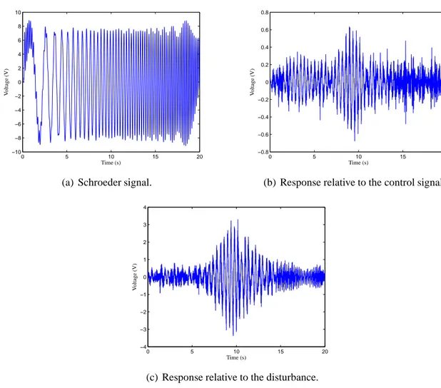
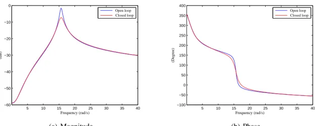
2.7 Frequency response comparison between the open-loop and the closed-loop systems. 56 2.8 Signals used to analyse the controller performance. . . 57
2.9 Frequency response of filterFu(s). . . 58
2.10 Frequency response comparison between open-loop and closed-loop systems. . . . 58
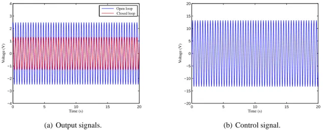
2.11 Simulated response when the disturbance is a chirp signal. . . 59
2.12 Simulated response when the structure is excited in its natural frequency. . . 59
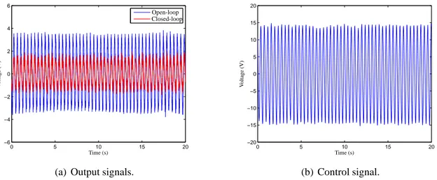
2.13 Experimental response when the disturbance is a chirp signal.. . . 60
2.14 Experimental response when the structure is excited in its natural frequency. . . 60
3.1 Block diagram of the modalH∞control problem. . . 69
3.2 Simulated structure. . . 70
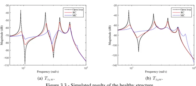
3.3 Simulated results of the healthy structure. . . 72
3.4 Performance comparison between open loop (black line with points), RC (red solid line), and MC (blue dotted line) for the simulated structure. . . 72
3.5 Control signal comparison between RC (red solid line) and MC (blue dotted line) for the simulated structure. . . 73
3.6 Experiment setup. . . 73
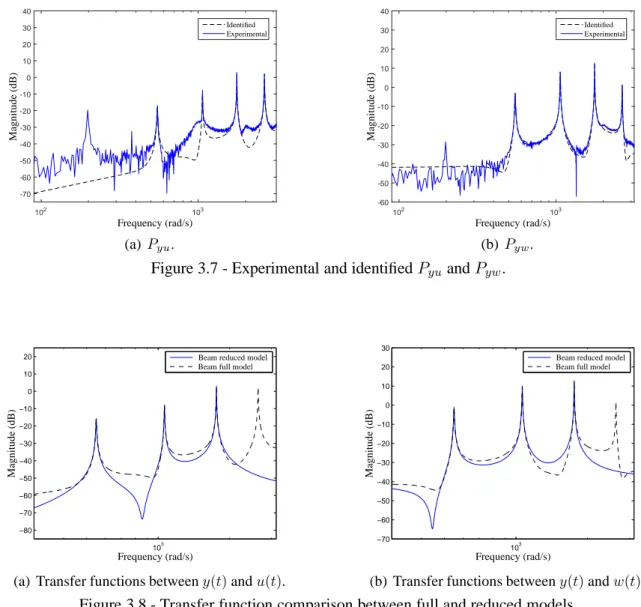
3.7 Experimental and identifiedPyuandPyw. . . 75
3.8 Transfer function comparison between full and reduced models. . . 75
3.9 Healthy beam simulated signals. . . 76
3.10 Frequency response comparison between healthy and damaged structures. . . 77
3.11 Experimental output signals. . . 78
3.12 Experimental control signals. . . 78
4.5 Detail B of Fig. 4.3(b): modification of the boundary conditions to simulate a
dam-age that models a crack of lengthh. . . 87
4.6 Mode shapes of the nominal model. . . 87
4.7 Transfer function comparison between complete and nominal models. . . 88
4.8 Frequency response comparison between the healthy and the damaged structure (Damage 3). . . 89
4.9 Modal distance estimation. . . 89
4.10 Frequency response comparison between the uncontrolled and the controlled healthy structure. . . 91
4.11 Performance comparison between the uncontrolled and the controlled healthy struc-ture. . . 91
4.12 Control signal comparison between the MC and the RC in the healthy structure. . . 92
4.13 Performance comparison of the controlled structure subjected to damage. . . 93
4.14 Control signal comparison of the controlled structure subjected to damage. . . 94
5.1 Single loop. . . 98
5.2 Double loop.. . . 98
5.3 FTC framework.. . . 99
5.4 Proposed DTAC framework. . . 100
5.5 Detailed block diagram of the proposed DTAC framework. . . 101
5.6 Frequency response comparison between the uncontrolled and the controlled healthy structure. . . 110
5.7 Performance comparison between the uncontrolled and the controlled healthy struc-ture. . . 110
5.8 Control signal comparison between the MC and the RC in the healthy structure. . . 111
5.9 Modal peak performance comparison of the controlled structure submitted to damage.113 5.10 Control signal components of the MDLF. . . 114
5.11 Adaptive gains of the damage compensator. . . 115
A.1 The angle between one-dimensional subspacesS1,S2 ∈ R3. . . 133
A.2 Configuration of each couple of piezoelectric layers (cross-section). . . 148
B.1 Dispositif expérimental.. . . 162
B.2 Amplitudes expérimentales maximales de vibration de chaque mode. . . 163
B.3 Signaux de commande expérimentaux pour les structures saine et endommagée. . . 163
B.4 Atténuation deTzlwet les amplitudes de crête respectives. . . 165
B.5 Structure en aluminium possédant des éléments actifs, modélisée par éléments finis et maillée avec des éléments plaque triangulaires (éléments DKT) . . . 167
B.6 Distances modales en fonction du dommage.. . . 167
B.7 Structure soumise au dommage 3: comparaison des réponses. . . 168
B.8 Comparaison de signaux de commande. . . 168
B.9 Le bloc-diagramme détaillé du système de DTAC. . . 170
2.1 Parameters to simulate the Kanai-Tajimi spectra.. . . 54
4.1 Structure mechanical properties. . . 87
4.2 Mechanical and electrical properties of the piezoelectric elements (NOLIACr). . . 87
4.3 First natural frequencies of the healthy structure.. . . 88
4.4 Parameters of the weighing filters. . . 90
4.5 Healthy beam modal responses with the regular controller. . . 90
4.1 Damage-tolerant controller design. . . 84
5.1 Nominal controller design. . . 108
AMD Active Mass Driver
ATAC Adaptive Tolerant Active Control
AVC Active Vibration Control
DC Direct Current
DMC Department of Computational Mechanics
DOF Degree Of Freedom
DTAC Damage-Tolerant Active Control
EDAC Evolving Damage Active Control
EFR Experimental Frequency Response
ENSAM École Nationale Supérieure d’Arts et Métiers
FDI Fault Detection and Isolation
FE Finite Element
FEM School of Mechanical Engineering
FTC Fault-Tolerant Control
IMSC Independent Modal Space Control
LMI Linear Matrix Inequality
MC ModalH∞Controller
MDLF Modal Double-Loop Framework
MIMO Multiple-Input and Multiple-Output
PAC Preventive Active Control
PIMM Laboratory of Process and Engineering in Mechanics and Materials
PWM Pulse-Width Modulation
PZT Lead Zirconate Titanate
RC RegularH∞Controller
SHM Structural Health Monitoring
STAC Strictly Tolerant Active Control
AT transpose of matrix A
A∗ complex conjugate transpose of matrix A
t time
w(t) disturbances
u(t) control signals
y(t) measured outputs
p(t) nodal displacements
M mass matrix
D damping matrix
K stiffness matrix
Bw input matrix relative to w(t)
Bu input matrix relative to u(t)
Cd output matrix relative to p(t)
Cv output matrix relative to ˙p(t)
Cw output matrix relative to w(t)
Cu output matrix relative to u(t)
m number of modes
Φ modal matrix
q(t) modal displacements
Mm modal mass matrix
Dm modal damping matrix
Km modal stiffness matrix
Cdm modal displacement output matrix
Cvm modal velocity output matrix
Ω matrix of natural frequencies
Z matrix of modal damping coefficients
x(t) state vector
1
C2 matrix of measured outputs
D11, D12, D21, D22 direct transmission matrices
s Laplace variable
ς(s) Laplace transform ofς(t)
P(s) plant transfer matrix
K(s) controller transfer matrix
Pzw(s) transfer function matrix between Z(s) and W(s)
Pzu(s) transfer function matrix between Z(s) and U(s)
Pyw(s) transfer function matrix between Y(s) and W(s)
Pyu(s) transfer matrix between Y(s) and U(s)
xc(t) controller state vector
Ac controller dynamic matrix
Bc controller input matrix
Cc controller output matrix
Dc controller direct transmission matrix
Tuw(s) closed-loop transfer function matrix between U(s) and W(s)
Tzw(s) closed-loop transfer function matrix between Z(s) and W(s)
k · k∞ infinity norm
˜
A closed-loop dynamic matrix
˜
B closed-loop input matrix
˜
C closed-loop output matrix
˜
D closed-loop direct transmission matrix
Fu weighing filter applied to u(t)
Fz weighing filter applied to z(t)
ωc transition frequency between rejection band and passband
k filter order
¯z(t) z
Gn(s) transfer function matrix of the nominal plant
Gg(s) transfer function matrix of the generalised plant
mi massi kg
Nsp(s) Kanai-Tajimi spectrum
˜
Wi(s) bandi disturbances in the frequency domain
˜
wi(t) bandi disturbances in the time domain
˜
Yi(s) responses in the frequency domain of bandi
˜
yi(t) responses in the time domain of bandi
Fi ideal bandpass filter for bandi
G(s) stable linear time-invariant transfer matrix
sup supremum
inf infimum
¯
Yi(s) responses in the frequency domain of modei
¯
yi(t) responses in the time domain of modei
Qi diagonal matrix that weights modei
k · k∞,Q weighted modalH∞norm
diag(·) diagonal matrix
zp(t) modal performance vector
Γ, Θ, Λ matrices of modal performance vector
Tzpw(s) closed-loop transfer function matrix between Zp(s) and W(s)
k stiffness coefficient N/m
d damping coefficient Ns/m
Saa power spectral density ofa(t)
Sba cross power spectral density betweenb(t) and a(t)
M(·) stable model
O∞(M(·)) infinite observability matrix ofM(·)
O∞(Mi) infinite observability matrix of a modal subsystemMi ∆i(Mi(1), M (2) i ) distance between M (1) i andM (2) i for modei ¯
q vector that balances the vibration reduction achieved by the H∞
controller and the relative effect of damage for each mode
αi mode peak amplitude of the controlled structure
φi mode peak reduction
q linear transformation of vectorq into a reasonable range¯
h crack length
f(t) fault signal
C1 controller 1
C2 controller 2
ϕ(t) bounded unknown signal that represents damage
u1(t) control signal generated by the nominal controller
u2(t) control signal generated by the damage compensator
xr(t) reference state
ex(t) residue
ˆ
x(t) state-vector estimation
ˆ
y(t) output-vector estimation
L modal observer gain
e(t) estimation error
Jϕe performance index
V (·) Lyapunov function
w∗(t) worst-case disturbance
Ki modei gain vector
Ku1 gain vector over u1
Ar reference dynamic matrix
B1r reference matrix of disturbance inputs
B2r reference matrix of control inputs
ˆ
Tx, Tu1 adaptation-rate matrices
Ti modei adaptation rate
tr(·) trace of a matrix
ωc1 first cutoff frequency of the bandpass filter
ωc2 second cutoff frequency of the bandpass filter
exi(t) residue relative to modei
| · | absolute value
[a∢b] angle between vectorsa and b
[A∢B] principal angles between row(A) and row(B)
cos cosine
S linear subspace
rank(A) rank of matrix A
row(A) row space of matrix A
range(A) column space of matrix A
λ(A) eigenvalues of matrix A
max maximum
1 INTRODUCTION . . . 29 1.1 Motivations . . . 29
1.2 State of the art of the DTAC domains . . . 30
1.2.1 Smart structures . . . 31
1.2.2 Structural health monitoring . . . 32
1.2.3 Active vibration control . . . 33
1.2.4 Fault-tolerant control . . . 35
1.2.5 Damage-tolerant active control . . . 36
1.3 Objective of the thesis . . . 38
1.4 Organisation of the thesis . . . 39
1.5 Publications arising from this thesis . . . 40
2 ACTIVE H∞CONTROLLER FOR VIBRATION REJECTION . . . 42
2.1 Introduction . . . 42
2.2 State-space modal representation of flexible structures . . . 42
2.3 H∞control problem . . . 45
2.4 H∞control solution using the LMI approach . . . 47
2.5 Weighing filters . . . 50
2.6 Application: vibration control of a vertical structure subject to seismic events . 52
2.6.1 Structure description and identification . . . 53
2.6.2 Controller design . . . 56
2.6.3 Experimental results . . . 59
2.7 Conclusion . . . 60
3 A MODAL H∞-NORM APPROACH APPLIED TODTAC . . . 62
3.1 Introduction . . . 62
3.2 Modal norm definition . . . 63
3.3 Modal control problem . . . 66
3.4 Modal control solution . . . 68
3.5 Simulated and experimental results . . . 69
3.5.2.3 Control system experimental results . . . 77
3.6 Conclusion . . . 79
4 A MODAL H∞-NORM PERFORMANCE REQUIREMENT FOR DTAC . . . 80
4.1 Introduction . . . 80
4.2 Assessing damage effects . . . 81
4.2.1 Modal damage metric . . . 82
4.2.2 Modal weighing matrices . . . 83
4.2.3 Algorithm for the modal damage-tolerant controller design . . . 84
4.3 Simulated results with FE models. . . 85
4.3.1 Simulated flexible structure . . . 85
4.3.2 Damage simulation . . . 88
4.3.3 Regular robust controller design . . . 89
4.3.4 Modal robust controller design . . . 90
4.3.5 Healthy structure responses . . . 91
4.3.6 Controller responses under damage. . . 92
4.4 Conclusion . . . 95
5 A MODAL DOUBLE-LOOP CONTROL FRAMEWORK FOR DTAC . . . 96
5.1 Introduction . . . 96
5.2 Adopted DTAC framework . . . 97
5.3 Reconfigurable DTAC controller . . . 100
5.3.1 Modal observer design . . . 101
5.3.2 Reference model . . . 104
5.3.3 Damage compensator . . . 105
5.3.4 Reconfiguration mechanism . . . 106
5.3.5 Modal double-loop controller design procedure . . . 108
5.4 Simulated results . . . 108
5.4.1 Damage simulation . . . 109
5.4.2 Nominal controller design . . . 109
6 GENERAL CONCLUSIONS AND FUTURE PERSPECTIVES . . . 117
REFERENCES . . . 120
APPENDIX A - THE PRINCIPAL ANGLES BETWEEN SUBSPACES . . . 133
A.1 The angles between two vectors . . . 133
A.2 Principal angles and directions . . . 134
A.3 The principal angles and respective directions as eigenvalues and eigenvectors . 135
A.4 The cosines of the principal angles based on LQ decomposition . . . 136
ANNEXE A - THE PRINCIPAL EQUATIONS OF THE PLQP SOFTWARE . . . 138
ANNEXE B - RÉSUMÉ ÉTENDU EN FRANÇAIS . . . 156
B.1 Introduction . . . 156
B.2 Objectifs . . . 157
B.3 Modèle modal d’une structure intelligente . . . 157
B.4 CommandeH∞modale . . . 160
B.4.1 Résultats expérimentaux . . . 162
B.5 Prise en compte des effets des dommages dans la conception du correcteur modal163
B.5.1 Métrique modale pour détecter les dommages et identifier leur sévérité. 164
B.5.2 Détermination des matrices de pondération modale . . . 164
B.5.3 Résultats simulés . . . 166
B.6 Double boucle de commande . . . 169
B.6.1 Observateur modal . . . 169 B.6.2 Modèle de référence . . . 171 B.6.3 Compensation de dommage . . . 171 B.6.4 Mécanisme de reconfiguration . . . 172 B.6.5 Résultats simulés . . . 173 B.7 Conclusion . . . 174
1 I
NTRODUCTION1.1 Motivations
Advances in materials and associated technologies have been conducting to larger, light-weight, and more flexible structures. Considering this trend, engineering systems like aerospace
applications, robotic systems, and communication antennae (HU; NG,2005) are more
suscept-ible to disturbances caused by vibrations. This can lead these new structures to performance worsening, premature aging of materials, and eventually damage. In consequence, the interest in active vibration control has been increasing substantially and several different techniques
have been developed along the last years (ZABIHOLLAH et al., 2007; KHOT et al., 2011;
BRAGHIN et al.,2012;SHARMA et al.,2015).
Active Vibration Control (AVC) can be situated in the intersection between structural
mechanics and automation research areas (BALAS, 1978). Recently, the evolution of
micro-electronic and microcomputers, including also transducer integration, has conducted the
devel-opment of active control methods applied to structures (GAWRONSKI, 2008; PREUMONT,
2011). Two preliminary steps are commonly necessary to design active vibration controllers.
The first step is to model the structure using the Finite-Element (FE) method and/or experi-mentally identify the plant model, noticing that the respective transducers shall be in general
included in the final model (KATAYAMA, 2005). Sometimes, an analytical model is available
and is possible to adopt (MEIROVITCH,1986). Considering the very high number of adopted
modes, and the consequent number of equations, even for simple structures, the second step con-sists of reducing the model order aiming for a manageable model to design the controllers. The model order reduction may significantly affect the system performance and lead to instability. This phenomenon is known as spillover and must always be considered when designing active
vibration controllers (BALAS,1979).
A considerable variety of approaches to control flexible structures using robust
act-ive control may be found in the literature (SPENCER; NAGARAJAIAH, 2003;
GAWRON-SKI, 2008;CASCIATI et al., 2012). Considering the scope of this work, the following recent
strategies deserve to be cited: adaptive control (HU; MA,2006), fractional control (
JI-ANG; LI, 2010), resonant control (PEREIRA et al., 2011), sliding mode control (HU; ZHU,
2012), modal control (CINQUEMANI et al.,2015), and finallyH2 andH∞control in the
clas-sical approach (GAWRONSKI, 2004) and in the spatial approach (HALIM, 2002). However,
considering these references and even most other publications, it may be affirmed that regular control methods do not take into account the possibility of damage, representing a new chal-lenge to the active controller design.
The repeated exposition to loads and consequent vibration stress are responsible for ac-celerating the structure aging, which may change the material properties, usually leading to the occurrence of cracks. The reduction of vibration amplitude and its duration can provide an extension of the structure life, which represents a significant advantage for structures with vibration control mechanisms. The regular AVC consequence is to retard damage occurrence through the rejection of external disturbances. However, the model accuracy directly influences controlled robustness and performance, given that structural dynamics is sensitive to
opera-tional conditions, temperature, and structural damage (CHOMETTE et al.,2008;MECHBAL;
NÓBREGA, 2015a). In most cases, operational condition changes included in the controller
design can mitigate these effects. On the other hand, model changes due to structural damage are not easily incorporated into the control design because damage influence in the structure dynamics is difficult to predict. It is important to include the possibility of damage in the
struc-tural active control design, guaranteeing an acceptable performance (GENARI et al., 2015a).
The structure active vibration control research area considering these requirements is referred
to as Damage-Tolerant Active Control (DTAC) (MECHBAL; NÓBREGA, 2012). To include
damage compensation as an effective controller design requirement, guaranteeing closed-loop performance before and after the damage occurrence, this thesis presents novel methods to design damage-tolerant active controllers.
1.2 State of the art of the DTAC domains
DTAC is a multidisciplinary engineering research area, involving concepts of smart struc-tures, Structural Health Monitoring (SHM), AVC, and Fault-Tolerant Control (FTC). In order to discuss DTAC concepts, this section presents a short introduction to each of these domains, trying to focus on the main topics used to develop this work and presenting the adopted
assump-tions. After this, DTAC is introduced and some strategies to design the respective controllers are presented. In addition, the relation between FTC and DTAC is discussed, showing important particular differences between the control methods of each area.
1.2.1 Smart structures
Smart structures have becoming increasingly present in industrial products, especially in applications that require strict performance and safety such as aerospace and civil engineer-ing areas. They can be defined as a structural system that responds to external stimuli usengineer-ing distributed transducers, often used to monitor the system condition, but that may also be used by control algorithms to change or adapt the structure itself or its dynamic behaviour. The de-velopment of the smart structure field is linked to the material science and the control fields. The material science is responsible for providing new materials for sensing and actuation, in an efficient and controlled manner, encompassing the effective integration of transducers in structures. The control techniques are responsible for analysing the structure response in order to produce actuating signals by adjusting structural characteristics such as shape, stiffness, or
damping (FISCHER, 2013).
This thesis deals with the vibration attenuation of smart structures. These vibrations are caused by external disturbances such as wind, seismic events, loads, etc. The smart struc-tures should be able to sense the vibrations and react through a control algorithm to atten-uate them. There is a wide range of materials to be used as transducers, comprising piezo-electric, electrostrictive, magnetostrictive, carbon nanotubes, shape memory alloys, and
oth-ers (SRINIVASAN; MCFARLAND, 2001). In this research, piezoelectric patches are adopted
to work as sensors and/or actuators.
Piezoelectricity is an electromechanical interaction phenomenon, representing the coup-ling between mechanical deformations and electric fields in a material. In 1880, Pierre and Paul-Jacques Curie discovered the direct piezoelectric effect on various crystals such as tourmaline, Rochelle salt, and quartz. The researchers noted that these crystals generate electrical charges when they were mechanically strained in certain directions. In the following year, they also dis-covered that the crystals react to electric voltage with shape change. For this reason, the same
In this research, PZT (lead zirconate titanate) ceramic patches are adopted. These are the most used in the industry due to strong electromechanical coupling, ability to produce large forces, short reaction time, high precision, durability, low costs, and the patches can be found in diverse forms. PZT ceramics are indeed capable of simultaneously measuring deformation and transmiting force to the structure. In addition, piezoelectric elements are light and may be easily glued on the structure body or incorporated inside composite materials.
1.2.2 Structural health monitoring
Structures are subject to aging from repetitive strain, friction, loads, and differences in temperatures and pressures. The combination of these agents contributes to structure deterior-ation. An efficient damage detection can prevent catastrophic failures and save maintenance
costs (GENARI; NÓBREGA,2012). Thereby, in the last decades, damage detection and SHM
techniques have been investigated and several damage indicators have been proposed in the
lit-erature (MEVEL et al.,2003;FAN; QIAO,2010;BAPTISTA et al.,2014;SARTORATO et al.,
2017).
Damage may be defined as changes in the structure that adversely affect current or future performance. The damage concept makes sense by comparing two different substructure states: the initial state assumed as intact (or healthy) and the current state. There are several damage possibilities in smart structures, including damage in the respective transducers. For instance, the piezoelectric ceramic glued onto a structure may present the following damages: detachment of the ceramic, cracking of an electrode and/or a ceramic, disordering of a measuring cable, and breakdown of the piezoelectric material due to a high electric field. On the other hand, damage types in the structure body are several as well, depending on the structure material (metal alloys, composite materials, etc.). The most common damage types are cracks, debonding, deforma-tions and material loss caused by impacts, and “nonmechanical” damage. The damage is called “nonmechanical” due to its origin, such as thermal, electrical, or pressure phenomena. In this thesis, DTAC-proposed methods are examined using metallic structures.
Some techniques for damage diagnosis using nondestructive evaluation methods are be-ing developed, based on acoustic theory, magnetism, thermal science, x-ray, etc. These methods are usually applied to characterise the damage and to analyse the degree of severity but
re-quire previous knowledge of damage regions in structures (ZHENG; MITA,2007). In addition, nondestructive methods commonly require system downtime and therefore an operating loss. Hence, the techniques for SHM in real time have been widely investigated. These new ap-proaches have benefited from recent advances in smart materials, conducting to the deployment of new functions in smart structures.
There is a large number of approaches for designing SHM systems, in which it is
pos-sible to cite the following promising categories: classification problem (MECHBAL et al.,
2015), electromechanical impedance (SELVA et al., 2013), acoustic emission (HOLFORD
et al., 2009), Lamb waves (SOUZA; NÓBREGA, 2012), among others. However, structure
vibration-based methods permit to detect, locate, and analyse the severity of damage from changes in vibration characteristics such as modal frequencies, mode shapes, and flexibility
matrix (CARDEN; FANNING,2004;HUMAR et al.,2006;SAEED et al.,2009a;MEDEIROS
et al.,2016). This SHM approach usually provides valuable information about damage impacts on structural vibrations, which may be used to design and/or to reconfigure controllers to face the vibration changes. In this thesis, this SHM strategy is adopted to generate damage informa-tion used in the DTAC controller design.
1.2.3 Active vibration control
Active control methods of structure vibrations adopt a reduced order model, as already mentioned, in which the active term is due to the use of an external energy source. Continuous mechanical structures have an infinite number of vibration modes, implying that there are al-ways some neglected dynamics in the control system design. The order reduction is based on an effective frequency-of-interest band, which is determined based on control requirements and practical aspects. This causes the occurrence of the spillover phenomenon, corresponding to the excitation of out-of-interest-bandwidth natural frequencies, which may be considered the main active control limitation for real applications. Failure in properly considering spillover in the
controller design usually leads to instability (BALAS, 1978; BALAS, 1979; MEIROVITCH;
BARUH, 1985). Some proposed techniques render the problem manageable, adopting smart
structures with a great number of collocated sensors and actuators (INMAN,2001). The
struc-ture. Considering the small range of realistic applications using collocated methods, the control technique development for noncollocated mechanical structures has been receiving the
atten-tion of the scientific community (MECHBAL et al., 2006;SCHRÖCK et al., 2011). However,
noncollocated systems have more complex dynamics with non-minimum-phase zeros (
GOS-IEWSKI; KULESZA, 2013), making it difficult to achieve closed-loop robustness and good
performance (PREUMONT, 2011). Despite the progress achieved so far, the noncollocated
vi-bration control of structures remains challenging (MASTORY; CHALHOUB,2014).
Several control methods have been proposed to mitigate structure vibrations with different success levels. Avoiding the spillover occurrence and instability caused by parameter variation
may be considered the main issues to be solved in any control design method (MOHAMED
et al., 2005;BOSSI et al., 2011). However, current techniques are generally inadequate to be applied to plants with dynamic uncertainties because they are very sensitive to model
inaccur-acy (TANG; CHEN, 2009). H∞-based control methods are able to handle both uncertainties
and parameter variations, and have been successfully adopted to suppress low-order vibration
modes (BOULET et al., 2001;HALIM, 2004; ROBU et al., 2010). Due to these
characterist-ics, H∞ methods have been used in active vibration control (NONAMI; SIVRIOGLU, 1996;
ZHANG et al., 2009;GENARI et al.,2015). The H∞ controller goal is to minimise the worst mode performance in the interest bandwidth, without excitation of the neglected dynamics. To achieve this effect, conveniently designed weighing filters are necessary to shape the desired
fre-quency distribution (SERPA; NÓBREGA,2005). The respective approach deals in general with
low frequency bands as a whole, which prevents mode selectivity in terms of both amplitude and frequency in the interest bandwidth. This behaviour compromises the interest-bandwidth
excitation relative to the control signal, as a result of the so-called water bed effect (ZHOU;
DOYLE,1997).
Early papers by Balas(1978) andMeirovitch et al. (1983) introduced the modal control
aiming for specific structure modes. Meirovitch developed the Independent Modal Space Con-trol (IMSC), where each mode is conCon-trolled separately. However, IMSC was very sensitive with respect to spillover and improvements were proposed to make the method more tolerant to this
phenomenon (RESTA et al., 2010). For instance, Baz and Poh(1990) suggested the modified
independent modal space control to overcome the spillover problem in the IMSC, adopting
an optimal actuator placement technique.Fang et al.(2003) modified the IMSC algorithm for
uncontrolled modes, considering the effects of residual modes and their connection with the
de-pendent modal space controller, based on mode shape modifications by creating virtual nodes in
desired locations. In parallel, other modal methods have been developed (INMAN,2001;KIM
et al., 2011; PEREIRA et al., 2011). Despite the evolution, the design of an efficient modal
controller to face the spillover effects continues as an open problem (CINQUEMANI et al.,
2015).
In all those analysed works on vibration control of flexible structures, the general strategy is to measure and to reduce the structure vibration at specific locations, adopting point-wise models. However, this strategy ignores the vibration effects on the rest of the structure, which may lead to performance loss if vibration attenuation over the entire structure is necessary.
To overcome this limitation, the spatialH2 norm was proposed in (MOHEIMANI; FU, 1998)
and the spatialH∞ norm was proposed in (MOHEIMANI et al., 1997; MOHEIMANI et al.,
1998), which are performance measures over the spatial domain. Both spatial norms can be
seen as natural extensions of the regular H2 and H∞ norms for spatially distributed
sys-tems (HALIM; MOHEIMANI, 2002b), leading to control problems that can be solved using
regular approaches (HALIM; MOHEIMANI, 2002a). Successful experimental studies have
been conducted byHalim(2002) and byLee(2005) to test the spatialH∞approach.
1.2.4 Fault-tolerant control
FTC is a control design methodology that can tolerate some system component faults, maintaining stability and an acceptable level of performance. These components are here under-stood as sensors, actuators, controllers, and plant parts. In general, the FTC system is designed with the ability to accommodate system faults automatically. During the last three decades,
FTC has been applied to improve system reliability, maintainability, and survivability (ZHAO,
1999). Nowadays, FTC approaches have been increasingly used and researched in industrial
and academic areas. Several survey papers have been published, using different approaches for
different types of systems (FEKIH,2009;KHELASSI et al.,2011;WANG et al.,2015).
Generally, there exist two approaches to FTC: passive and active. It is worth mentioning that this definition is completely different from the vibration control area, where the active and the passive terms are relative to the use or not of an external energy source.
not possible to change, based on a priori knowledge about component faults (HSIEH, 2002).
These controlled systems must be robust with respect to the expected faults (JIANG; ZHAO,
2000). In this approach, fault tolerance is usually achieved by considering faults as uncertainties
or external perturbations that the control systems should compensate. In general, the designer
works with an adopted set of system-fault scenarios (ZHAO,1999). However, the FTC system
performance may not respond satisfactorily to an unexpected fault, eventually leading the plant to instability.
In the active approach, the FTC controller reacts to the system component fault, reconfig-uring the controller parameters to maintain the system stability with desired performance. For this purpose, a real-time Fault Detection and Isolation (FDI) module is necessary to provide
usable data about the plant state (KLINKHIEO,2009). In this FTC strategy, the controlled
sys-tem performance is related to the accuracy of the fault information and the robustness of the FDI to disturbances. The active FTC methods must be able to deal with several types of faults, including unexpected faults. There are several approaches to design FTC systems, of which
some examples are given in (YANG et al.,2010). To conclude, (ZHANG; JIANG,2008) shows
a good review of active FTC methods.
1.2.5 Damage-tolerant active control
The DTAC method development constitutes a recent research area that has intersections with both FTC and AVC areas. Specific FDI techniques are used by fault-tolerant controllers to provide online parameter adaptation aiming to maintain an adequate performance for
con-trolled systems (ZHANG; JIANG, 2008; RODRIGUES et al., 2014; WANG et al., 2015). In
the same way, DTAC methods use SHM techniques to design controllers presenting
damage-tolerance (MECHBAL; NÓBREGA,2012). DTAC methods may be considered an extension of
FTC, focusing fundamentally on structural vibration control, aiming to expand the applicability of modern smart structures. However, adapting FTC methods to face damage-induced vibra-tion in flexible structures leads to new challenges. The infinite number of structural vibravibra-tion modes demands a controller robustness that is complicated by the dynamic changes due to
dam-age perturbation (MECHBAL; NÓBREGA,2015). The literature regarding vibration control of
placement technique together with a root mean square method to locate and to mitigate the
dam-age caused by delamination in a composite plate.Umesh and Ganguli (2008) investigated the
negative velocity feedback control algorithm to compensate the damage effects.Ripamonti et al.
(2015) proposed an adaptive active vibration control to increase the structure life, emphasising
the vibration reduction from the most damaging modes.
DTAC arises from intense investigation to bring more secure and efficient operations to
flexible structures, aiming for extension of their life cycle as well (MECHBAL; NÓBREGA,
2015b). The first goal of DTAC methods is to achieve an adequate performance for healthy
real-life structures. For this purpose, DTAC systems need to be able to solve the regular active
control problem, which involves avoiding the spillover phenomenon (BALAS, 1978) and
ad-opting noncollocated transducers on the mechanical structures (KIM; OH, 2013). In addition,
as a second goal, the controlled system should prevent and/or retard damage occurrence. This basic DTAC idea corresponds to reducing the vibration. The third goal is that, in the event of structural damage, the controller should act to mitigate damage effects on structural vibrations,
avoiding or delaying damage propagation (MECHBAL; NÓBREGA,2015a).
DTAC strategies are based on the structure state condition, depending if the structure is
healthy or damaged (MECHBAL; NÓBREGA, 2012). For the healthy structure condition, two
strategies can be adopted (MECHBAL; NÓBREGA,2015b):
• Strictly Tolerant Active Control (STAC);
• Preventive Active Control (PAC).
STAC represents a robust approach based on a nonreconfigurable controller, aiming to guarantee an acceptable performance for some types and severity levels of future damage. How-ever, the compromise between robustness and performance may lead to unsatisfactory behaviour in damage absence, due to the natural opposition between these two features. To overcome this
limitation,Genari et al.(2015b) proposed a robust modal approach that leads to a reasonable
compromise between robustness and performance, in which both the healthy structure and the damaged structure have an adequate performance level with the same controller.
PAC is a preventive strategy aiming to avoid or to retard damage occurrence, consequently
extending structure life. For instance,Chomette et al. (2010) designed a controller that
atten-uates the most damaging modes.Ambrosio et al.(2014) included material fatigue into a cost
function, which is then minimised to obtain the PAC controller.
If damage occurs and is identified, two other possible strategies can be applied (
• Evolving Damage Active Control (EDAC);
• Adaptive Tolerant Active Control (ATAC).
The EDAC strategy admits that damage is detected, localised, and quantified. The con-troller is then designed to limit damage propagation, aiming to reduce vibration energy at the damage region. This strategy designs controllers that act over specific regions of the structure.
For instance, it corresponds to the spatialH∞ methodology applied to structural damage
con-trol that was investigated in (MECHBAL; NÓBREGA,2015b).Ashokkumar(2015) proposed
an actuator load to reduce vibration response magnitudes for damage growth control.
The ATAC strategy goal is to detect and then accommodate the damage, providing a sat-isfactory performance level for the controlled system in all circumstances. For this purpose, an SHM module and a reconfigurable controller are used to compose the control system. The SHM module must detect and analyse the damage and signal the controller to be reconfigured according to the SHM data. The ATAC strategy was used to design a damage-tolerant controller
in (MECHBAL; NÓBREGA,2015a) using a Lamb wave-based SHM module to localise
dam-age. Then, the spatial H∞ controller was reconfigured to reduce vibration energy flow in the
detected damaged region.
1.3 Objective of the thesis
The thesis objective is the development of DTAC methods applied to vibration control
of flexible structures subject to damage. First, in the regular AVC research area, a modalH∞
technique is proposed and applied to vibration control of the healthy structure, based on a new
modalH∞norm. Furthermore, considering the reasonable compromise between robustness and
performance achieved with the proposed methodology, the modal technique is adopted as an STAC strategy for damage active tolerance.
Based on the results of the modal H∞ approach to face damage, and considering that
structural damage impact may be represented by a modal composition, a methodology to design
the modalH∞controller including damage in the design requirements is proposed. For this
pur-pose, a new damage indicator based on model subspace distance is also developed, in order to
quantify modal damage effects. The modalH∞norm is computed based on the modal distances
minimisa-tion of the respective norm. This methodology configures a PAC strategy, but it may also be used as an EDAC one if the damage is already known.
As a final contribution, a double-loop control framework for the vibration attenuation of structures is proposed, performing the ATAC strategy. In this case, the controller in the first loop is designed to comply with the healthy structure requirements, based on the developed modal
H∞control, and the second-loop controller is designed to compensate eventual damage effects.
To achieve this goal, an online-reconfigurable technique is used in order to design the second controller, based on a modal state-tracking method to provide the updating of the controller parameters.
1.4 Organisation of the thesis
The thesis is organised into the following chapters:
Chapter 2: Active H∞controller for vibration rejection
The chapter introduces the H∞ control technique to attenuate the vibrations in flexible
structures, based on the LMI approach. This method is used to design regular vibration con-trollers but represents a fundamental step to design all the proposed damage compensators. The
regular H∞ controllers are used as the reference to assess the performance of the proposed
controllers. Initially, the chapter presents a brief overview of the state-space representation to describe generic flexible structures, adopting a modal representation according to the proposed controller design methods. Moreover, the chapter presents an overview of the LMI approach to
solve theH∞problem, including the weighting filters to impose the desired frequency response
in the controller design. After that, this control technique is used to attenuate vibrations of a bench-scale structure that simulates a tall building subject to seismic loads. The controller is designed to reduce the vibration level considering the control input limit.
Chapter 3: A modal H∞-norm approach applied to DTAC
A new approach for vibration reduction of flexible structures subject to damage is
presen-ted in this chapter, based on the proposed modalH∞norm. Considering that structural damage
provokes different effects on each vibration mode, the proposed method focus on the control action on specific modes that are indeed suffering the worst damage consequences. For this
convenience. Based on this norm, a regular H∞ controller design is applied, using the LMI approach. Simulated and experimental results are presented to show the modal methodology applicability.
Chapter 4: A modal H∞-norm performance requirement for DTAC
The modalH∞ design is extended in this chapter to implement a PAC strategy.
Consid-ering the different damage effects, the proposed methodology adopts the modalH∞ norm to
include damage as a design requirement. The basic idea is to create an appropriate energy dis-tribution over the frequency range of interest, aiming for specific vibration modes, guaranteeing robustness, damage tolerance, and an adequate overall performance. For this purpose, an SHM technique is applied to evaluate modal modifications caused by damage. This information is
used to create modal weighing matrices, conducting to the modal H∞ controller design. FE
models are adopted for a case study structure, including crack simulation, in order to evaluate the proposed control strategy.
Chapter 5: A modal double-loop control framework for DTAC
This chapter presents an implementation of the ATAC strategy, designing two controllers to be used in a double loop, aiming for vibration reduction of flexible structures subject to damage. The two controller design methods are presented, with emphasis in the reconfigurable controller that faces the damage. To assess the proposed method, FE models including healthy and damaged conditions are simulated with different controllers. Results are compared to assess the efficiency of the proposed controller design method.
Chapter 6: Conclusions
The thesis is concluded by stating the main contributions of this research. Moreover, this chapter presents recommendations for further research in this area.
1.5 Publications arising from this thesis
This work has been the subject of the following publications:
Journal papers:
• “Damage-Tolerant Active Control Using a ModalH∞-Norm-Based Methodology”,
Engineering Practice, 2016, accepted with minor revision.
• “A Reconfigurable Damage-Tolerant Controller Based on a Modal Double-Loop
Framework”, H. F. G. Genari and N. Mechbal and G. Coffignal and E. G. O. Nóbrega, Mechanical Systems and Signal Processing, 2016, under review.
• “A ModalH∞-Norm-Based Performance Requirement for Damage-Tolerant Active
Controller Design”, H. F. G. Genari and N. Mechbal and G. Coffignal and E. G. O. Nóbrega, Journal of Sound and Vibration, 2016, under review.
Conference papers:
• “A Modal H∞ Control Methodology for Damage-Tolerant Active Control”, H. F.
G. Genari and N. Mechbal and G. Coffignal and E. G. O. Nóbrega, 9th IFAC Symposium on Fault Detection, Supervision and Safety for Technical Processes, Paris -France, 48(21), 664-669, 2015.
• “A Double-Loop Control Approach Applied to Damage-Tolerant Active Control”,
H. F. G. Genari and N. Mechbal and G. Coffignal and E. G. O. Nóbrega, 23rd International Congress of Mechanical Engineering, Rio de Janeiro - Brazil, 1-8, 2015.
• “Robust Vibration Control of a Vertical Flexible Structure Subject to Seismic
Events”, H. F. G. Genari and O. Oliveira Neto and E. G. O. Nóbrega and N. Mechbal and G. Coffignal, XVII International Symposium on Dynamic Problems of Mech-anics, Natal - Brazil, 1-10, 2015.
• “Structural Damage Diagnosis Method Based on Subspace Identification Metric”,
H. F. G. Genari and E. G. O. Nóbrega and N. Mechbal, 22nd International Congress of Mechanical Engineering, Ribeirão Preto - Brazil, 4200-4208, 2013.
2 A
CTIVEH
∞ CONTROLLER FOR VIBRATION REJECTIONThe chapter goal is to present a brief overview of the LMI approach to solve the H∞
problem, representing a fundamental step to design the damage controllers presented in the next chapters. A modal state-space model of a generic structure is introduced in the sequence.
After that, the formulation and solution of the respectiveH∞ problem are conducted. Finally,
the robust control method is experimentally examined in a simulated tall building.
2.1 Introduction
The active controller design based on theH∞approach has been attracting attention due
to its robustness to modelling errors and disturbance rejection capability. Usually, theH∞
con-trollers are computed using two different approaches: Riccati equations and LMIs. The LMI approach has the advantage of easily including additional inequations while keeping its
convex-ity, permitting to be solved by efficient algorithms (NESTEROV; NEMIROVSKI,1994).
Considering that theH∞controller goal is to minimise the energy gain between the
out-put and the disturbance in the interest bandwidth, without excitation of the neglected dynam-ics, conveniently designed weighing filters are adopted to ensure the desired frequency
distri-bution (SERPA; NÓBREGA, 2005). The weighing filters shape the output responses and the
control signals, obtaining a reasonable trade-off between performance and robustness and con-sidering the frequency distribution based on the plant reduced model. The chapter presents a
brief overview of the LMI approach to solve theH∞problem, including the weighing filters in
the design procedure.
2.2 State-space modal representation of flexible structures
This section presents a brief overview of the modal state-space representation to describe a generic flexible structure, for the sake of completeness. This overview begins with a
second-order matrix differential equation, commonly used to represent structural dynamics by means of FE models. Then, the state-space model is defined from this differential equation, using a specific state-vector definition. To conclude, the transformation matrices to obtain different modal canonical representations are discussed.
A generic flexible structure can be modelled by the following second-order differential pair of equations:
Mp(t) + D ˙p(t) + Kp(t) = B¨ ww(t) + Buu(t) (2.1)
y(t) = Cdp(t) + Cv˙p(t) + Cww(t) + Cuu(t), (2.2)
in which p(t) denotes the displacements, M is the mass matrix, D is the damping matrix,
K is the stiffness matrix, Bw and Bu are the respective input matrices, where w(t) are the
disturbance forces acting on the structure and u(t) are the control forces, and y(t) are the
measured output signals modelled through the output matrices Cd, Cv, Cw, and Cu. In general,
FE models generate high order models, which need to be reduced to represent the bandwidth
of interest for the controller operation. Therefore, a model withm modes is considered, which
leads to the following modal matrix:
Φ=h φ1 φ2 . . . φm
i ,
where φi is the ith mode shape. A transformation into modal coordinates is obtained using
p(t) = Φq(t). Pre-multiplying Eq. (2.1) by ΦT and writing y(t) in terms of q(t) gives:
ΦTMΦ¨q(t) + ΦTDΦ˙q(t) + ΦTKΦq(t) = ΦTBww(t) + ΦTBuu(t)
y(t) = CdΦq(t) + CvΦ ˙q(t) + Cww(t) + Cuu(t),
which may be written as:
Mmq(t) + D¨ m˙q(t) + Kmq(t) = Bwmw(t) + Bumu(t) (2.3) y(t) = Cdmq(t) + Cvmq(t) + C˙ ww(t) + Cuu(t), (2.4) where Mm = ΦTMΦ, Dm = ΦTDΦ, Km = ΦTKΦ, Bwm = Φ TB w, Bum = Φ TB u,
Cdm = CdΦ, and Cvm = CvΦ. Matrices Mm and Km are diagonal while Dm is not
linear combination of the stiffness and mass matrices, D= αM+βK for α,β ≥ 0 (
GAWRON-SKI,2004). This is a reasonable and usual assumption, considering that flexible structures have
small damping factors.
Assuming that the matrix Mm is nonsingular, Eq. (2.3) can be written as:
¨ q(t) + M−1mDm˙q(t) + M−1mKmq(t) = M−1mBwmw(t) + M −1 mBumu(t), (2.5) and equivalently: ¨ q(t) + 2ZΩ ˙q(t) + Ω2q(t) = M−1 mBwmw(t) + M −1 mBumu(t), in which Ω2 = M−1
mKm, Z = 0.5M−1mDmΩ−1, Bm = M−1mΦTB0, and q(t) represents the
modal displacement vector. Moreover, Ω is the matrix of natural frequencies and Z is the modal damping matrix, both defined as:
Ω= ω1 0 · · · 0 0 ω2 · · · 0 .. . . . .. ... 0 0 · · · ωm and Z= ζ1 0 · · · 0 0 ζ2 · · · 0 .. . ... . .. ... 0 0 · · · ζm ,
whereωiandζiare respectively the natural frequency and damping relative to modei.
Adopting the state-vector definition as x(t) = [xT
1(t) xT2(t)]T = [qT(t) ˙qT(t)]T,
Eq. (2.4) and Eq. (2.5) can be transformed into:
˙x1(t) = x2(t)
˙x2(t) = −M−1mKmx1(t)− M−1mDmx2(t) + M−1mBwmw(t) + M
−1
m Bumu(t)
y(t) = Cdmx1(t) + Cvmx2(t) + Cww(t) + Cuu(t),
leading to the following state-space representation:
˙¯x(t) = ¯Ax(t) + ¯¯ B1w(t) + ¯B2u(t)
y(t) = ¯C2x(t) + D¯ 21w(t) + D22u(t),
using: ¯ A= 0 I −M−1 mKm −M−1mDm , ¯B1 = 0 M−1mBwm , and ¯B2 = 0 M−1mBum .
Finally, this model can be written into modal canonical representations using
transform-ation matrices (GAWRONSKI, 2004). For the purpose of the thesis approach, the following
state-space model structure is adopted:
A = A1 0 · · · 0 0 A2 · · · 0 .. . ... . .. ... 0 0 · · · Am , B1 = b11 b12 .. . b1m , B2 = b21 b22 .. . b2m , and C2 = cT21 cT22 .. . cT2m T , (2.6)
where it is possible to see that the system matrix has a block diagonal structure where each Ai
is a2× 2 matrix for i = 1, . . . ,m, therefore isolating each mode.
2.3 H∞control problem
According to the optimal controller design framework, a performance indicator is
intro-duced as an output vector z(t), leading to the following state-space equations:
˙x(t) = Ax(t) + B1w(t) + B2u(t)
z(t) = C1x(t) + D11w(t) + D12u(t)
y(t) = C2x(t) + D21w(t) + D22u(t), (2.7)
in which matrices C1, D11, and D12 are chosen to define the desired performance vector. All
vectors and matrices have appropriate dimensions related to the number of inputs and outputs and to the model order.
The H∞ control problem can be summarised in the block diagram of Fig. 2.1. In this
figure, y(t) is the output vector measured from the structural response, z(t) is the performance
and the controller are respectively represented by transfer matrices P(s) and Kc(s), where the
dynamic controller Kcis adopted with the following state-space representation:
˙xc(t) = Acxc(t) + Bcy(t) u(t) = Ccxc(t) + Dcy(t). (2.8) P Kc u(t) y(t) z(t) w(t)
Figure 2.1 - Block diagram of theH∞control problem.
From Fig.2.1, it is possible to write the following expression:
Z(s) Y(s) = P(s) W(s) U(s) = Pzw Pzu Pyw Pyu W(s) U(s) , (2.9)
in which Z(s), Y(s), W(s), and U(s) are respectively the Laplace transform of z(t), y(t),
w(t), and u(t).
Considering Eq. (2.9) and the control effort given by U(s) = Kc(s)Y(s), it leads to:
Y(s) = (I− Pyu(s)Kc(s))−1Pyw(s)W(s),
where the control effort can be written as:
U(s) = Kc(s)(I− Pyu(s)Kc(s))−1Pyw(s)W(s), (2.10)
in which [Kc(s)(I− Pyu(s)Kc(s))−1Pyw(s)] is the transfer matrix between u(t) and w(t),
defined as Tuw(s).
In relation to Z(s), it is possible to write the following equation from Eq. (2.9):
in which the following expression is obtained by considering Eq. (2.10):
Z(s) = [Pzw(s) + Pzu(s)Kc(s)(I− Pyu(s)Kc(s))−1Pyw(s)]W(s),
where [Pzw(s) + Pzu(s)Kc(s)(I − Pyu(s)Kc(s))−1Pyw(s)] represents the transfer matrix
between z(t) and w(t), defined as Tzw(s). Therefore:
Z(s) = Tzw(s)W(s).
The optimalH∞problem consists in finding a controller Kc(s) that minimiseskTzwk∞.
However, optimal H∞ controllers are generally not unique for MIMO systems. Usually, to
find an optimalH∞controller is often both numerically and theoretically complicated (ZHOU;
DOYLE,1997). One way to address this problem is to consider a feasible limitγ > 0, where
a suboptimal approach is adopted to minimisekTzwk∞. The approach is based on successive
iterations to find the controller Kc(s) such thatkTzwk∞ < γ.
2.4 H∞control solution using the LMI approach
Considering the controller given in Eq. (2.8) and the plant model described by Eq. (2.7),
initially with D22= 0 to facilitate the formulation, the closed-loop system is defined as:
˙˜x(t) = ˜A˜x(t) + ˜Bw(t) z(t) = ˜C˜x(t) + ˜Dw(t), in which ˜ A = A+ B2DcC2 B2Cc BcC2 Ac , ˜B= B1+ B2DcD21 BcD21 , ˜ C=h C1+ D12DcC2 D12Cc i , and ˜ D = D11+ D12DcD21.