OATAO is an open access repository that collects the work of Toulouse
researchers and makes it freely available over the web where possible
Any correspondence concerning this service should be sent
to the repository administrator:
[email protected]
This is an author’s version published in:
http://oatao.univ-toulouse.fr/27600
To cite this version:
Chen, Zhaoxi
and Qiao, Li and Hillairet, Julien and Song, Yuntao and Turq,
Viviane
and Wang, Peng and Laloo, Raphaël
and Bernard, Jean-Michel
and Lu, Kun and Cheng, Yong and Yang, Qingxi and Hernandez, Caroline
Development and characterization of magnetron sputtered self-lubricating
Au-Ni/a-C nano-composite coating on CuCrZr alloy substrate. (2019) Applied
Surface Science, 492. 540-549. ISSN 0169-4332
Development and characterization of magnetron sputtered self-lubricating
Au-Ni/a-C nano-composite coating on CuCrZr alloy substrate
Zhaoxi Chen
a,
b,
*
,
1, Li Qiao
c'
1, Julien H illairet
a, Yuntao Song
d, Viviane Turq
h,
Peng Wang
C,
Raphael Laloo
h,
Jean-Michel Bernard
a, Kun Lu
d, Yong Cheng
d, Qingxi Yang
d,
Caroline Hemandez
a•cEA, 1RPM, P-13108 S<lint-Pau-Lez-Duroru:e, Proru:e
b Institut Carnot CIRIMAT, UMR CNRS-UPS-INP 5085, lJn1vershi Paul-Sabatier, 118 rouu de Narbonne, 31062 Toulouse Cedex 9, Proru:e
• State Key LoborQl1)ry of Solld Lubri<:alion, Lanzhou 1nstltute of Chemcal Physks, CAS, Lanzhou 73()()()(), China d !nstltute of Plasma Physks, CAS, Hefei 230031, China
ARTIC LE IN FO ABSTRA CT
Keywords:
Au-NVa-C composite coatlng Self-lubricatlng
Magnetronsputtering Mechanlcal property Wear
Compounding Au-Ni with carbon (C) lubricants is a feasible approach to improve its mechanical properties and wear performance. I n this study, 3.5 µm-thick Au-Ni/C nanocomposite coatings with a low residual stress on CuCrZr substrates by magnetron sputtering were developed. Faœ-centered cubic and hexagonal close-packed stacking structures were both confirmed in the composite coatings based on transmission electron microscopy and X-ray diffraction analyses. Amorphous C (a-C) was confirmed to be the structure of C in the composite coatings, and its graphitization transition with an increase in the C content was validated by X-ray photoemission spectra and Raman spectroscopy. By compounding 0.88 wt% a-C, the haniness of the Au-Ni/a-C coating reached 400 HV, which is twiœ higher than that of the Au-Ni coating. The electrical resistivity of the Au-Ni/a-C coating is relatively stable with an increase in the a-C content. As graphitization occurred on the wear track, the produced composite coatings showed a minimum wear rate of 2.2
x
10-6 mm3 /Nm under atmospheric conditions, which is half that of the Au-Ni referenœ coating. Under vacuum, the wear performance of the produœd Au-Ni/a-C composite coatings was similar to that of the Au-Ni referenœ coating.1. Introduction
Au coatings are commonly used as contact materials to ensure sta bility and low contact resistance upon sliding contact in the electronics industry [1 4). Soft Au which is not alloyed is one of the best metals with a high electrical conductivity, and it shows excellent corrosion resistance under most working conditions. However, the low hardness of soft Au coatings leads to a low wear resistance and constrains their lifetime under applicable conditions involving intensive sliding move ment [5). In high reliability systems, high performance Au coatings are required, and alloying Au with a small amount of other metal elements, such as Co and Ni, can generate harder Au coatings which exhibit distinct perfor mance improvement [1,6 8). Hard Au coatings are gen erally obtained from acidic cyanide baths in which nickel or cobalt salts are added as the hardening/brightening agents [3,4,9 12). Although Au Ni and Au Co alloy coatings exhibit a higher wear resistance corn pared to soft Au, adding solid lubricant materials into alloy coatings is
•Corresponding author at CEA, IRFM, F-13108 Saint-Paul-Lez-Durance, France.
E-mail address: [email protected] (Z. Chen).
beneficial for decreasing the wear rate by minimizing the adhesive wear. Considering the high electrical conductivity requirement of coatings, carbon (C) nanomaterials are the most suitable solid lu bricants.
Reœntly, interest in compounding metal matrices with low di mensional C nanomaterials such as C nanotubes and graphene, by electroplating to improve their mechanical and chemical performance has been increasing. The results showed that strengthened by C nano materials, the corrosion resistance and wear resistance of the metal coatings are improved significantly [13 16). However, considering the high toxicity of a cyanide bath and the practical difficulties of pre venting agglomeration of nano particles in Au plating electrolytes to achieve a good particle suspension and uniform coating [7), magnetron sputtering is an attractive ahemative technique for hard Au based C composite coating deposition.
Amorphous C (a C) including diamond like C (DLC) with significant fraction of sp3 bonds and graphite like C (GLC) with a high content of
1 These authors made equal contributions
to
this work and shared the co-first authorship.frequency (RF) power supply, and four power values (100 W, 200 W, 300 W and 400 W) were selected to obtain Au Ni/a C composite coat ings with different C contents. The coating times for the Au Ni/a C layers were maintained constant as 55 min to control the total thick nesses of the layers.
2.2. Characterization of the Au Ni/a C coatings
The top surfaces and cross sectional surfaces of the deposited coatings were observed byfield emission scanning electron microscopy (FESEM) using a JEOL JSM 6700F electron microscope at an accel eration voltage of 5 kV. High resolution transmission electron micro scopy (HRTEM) images of the coating cross sections were captured using a TECNAI G2 F20 S TWIN (FEI, USA) instrument at an accel erating voltage of 200 kV equipped with an X ray spectroscopy (EDS) unit. Cross sectional samples for TEM observations were prepared on a Helios Nanolab 600i (FEI, Germany) focused ion beam system with Ga ions accelerating voltage of 30 kV for preliminary cutting and 5 kV for final milling. X ray diffraction (XRD) studies were carried out on a D4 Endeavor diffractometer (Bruker, Germany) with a Ni filter and Cu Kα radiation (λ = 1.541 Å, 40 kV, 40 mA). The XRD data were collected in the 2θ range of 10° 100° with a step scan of 0.0157°. Micro Raman spectroscopy was performed to investigate the structure of the C clus ters in the composite coatings and transfer layers on the wear track. The spectra were recorded at room temperature over a range of 100 2000 cm−1, using a Horiba LabRAM HR800 spectrometer coupled with a 532 nm laser operated at a power of 12 mW. X ray photoemis sion spectroscopy (XPS) was performed on a PHI Quantera scanning X ray microprobe using a monochromatic Al Ka X ray source (1486.6 eV). The base vacuum of the chamber was maintained at 9 × 10⁻⁹Torr, and an Ar+gun was used to clean the surface before measurement.
The adhesion properties of the coatings were evaluated using a CSM® commercial micro scratch tester with a Rockwell C diamond stylus. A progressive load from 1 N to 50 N with a loading rate of 49 N/ min and a scratch length of 4 mm were applied. The effects of the C content on the hardness and elastic modulus of the coatings were characterized at room temperature by using a CSM® ultra na noindentation tester with a Berkovich diamond tip under a maximum test force of 5 mN. The coating surface roughness and wear track to pography were measured by a 3D optical profiler (Sensofar, USA). The coating stresses were also evaluated on the 3D optical profiler by measuring the curvatures of the coating samples (Si substrates). The electrical resistivity of the coatings was measured by a four point probe. Then, the tribological performance was evaluated on a ball on disc tribometer equipped with a high vacuum pumping system against a GCr15 ball (Ø = 3 mm). 8000 cycles rotary sliding tests were performed at a linear speed of 8.4 cm/s and a normal contact force of 2 N.
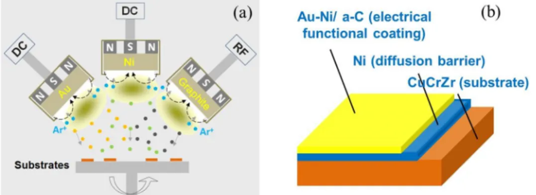
Fig. 1. (a). Schematic diagram of the Au-Ni/a-C magnetron sputtering system. (b). A sketch of the coating design.
sp2 bonds, has been widely researched as hardening or solid lubricant particles for the production of protective composite coatings by mag netron sputtering [17 19]. a C lubricated TiC and WC sputtered coat ings show a higher wear performance and significantly lower wear rates compared with pure coatings [20,21]. TiN/a GLC and silver doped DLC
coatings have been evaluated as biomaterials which exhibit a low coefficient of friction (CoF) and excellent hardness [22,23]. Me DLC
(Me: W, Mo, Nb, and Ti) co deposits have been investigated and they show good adhesion performance on substrates and an ultralow CoF of 0.03 [24]. However, there are almost no studies that have evaluated the
performance of hard Au coatings compounded with a C nanoparticles. The results would be interesting for directing advanced function coat ings development with integrated wear and electrical performance.
In this study, Au Ni/a C nanocomposite coatings with various C contents were deposited by magnetron sputtering. CuCrZr alloy has close electrical conductivity with pure Cu and it's mechanical perfor mance is much better than that of pure Cu. For some harsh application conditions like high temperature, CuCrZr alloy is more suitable than pure Cu as the structural material in the electrical industry. So, in this study, CuCrZr was selected as the substrate material for the Au Ni/a C deposition. Because Cu can diffuse with Au easily, before Au Ni/a C deposition, a few micron thick interlayers of pure Ni were applied onto the CuCrZr substrates. The effects of C content on the surface mor phology, microstructure, electrical and mechanical performance of the coatings were investigated and analyzed.
2. Experimental details
2.1. Preparation of the Au Ni/a C coatings
The Au Ni/a C nanocomposite coatings were deposited on CuCrZr substrates and p type silicon (100) wafers at room temperature. Fig. 1
shows a schematic diagram of the J450 magnetron co sputtering system used for this study with three targets (Au 99.99%, Ni 99.995%, gra phite 99.999%). The target to substrate distances for Au, Ni and gra phite targets were 6.5 cm, 8.5 cm and 5.5 cm respectively. Before the coating process, the silicon and CuCrZr substrates were ultrasonically cleaned for 10 min in acetone, followed by 10 min of cleaning in ethanol. For the CuCrZr plates, acid etching was performed for 30 s in 10 wt% H2SO4 to remove the passivation layers. The chamber was
pumped to its base vacuum of 9 × 10⁻⁴ Pa using a turbomolecular
pump set. The substrates were negatively biased and plasma cleaned at 500 V in a 2.5 Pa pure Ar atmosphere for 10 min. Before the coating deposition, the targets were pre sputtered to clean the targets and the chamber for 10 min. The coating deposition was carried out in two steps. Firstly, a pure Ni interlayer was deposited using a current of 1 A (390 V) at a pressure of 0.8 Pa with a 40 sccm Ar flow for 120 min. Then, the Au Ni/a C nanocomposite layer was deposited at 0.6 Pa with a Au target current of 0.35 A (400 V) and a Ni target current of 0.14A (290 V). The graphite target was sputtered using a 13.56 MHz radio
3. Results and discussion 3.1. Morphology
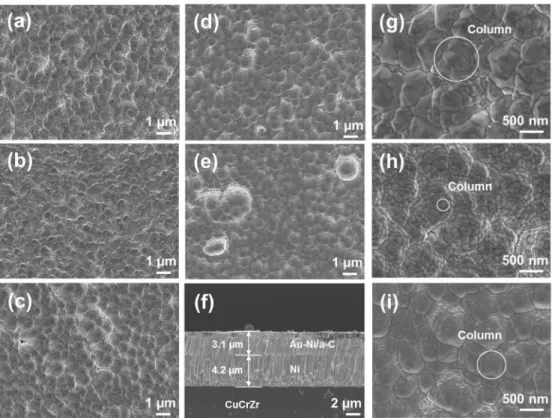
As shown inFig. 2, the composite coatings showedfish scale like morphologies, indicating that the coatings had columnar structures. For all the sputtering powers, the coatings presented dense structures, and no distinct coating defects, such as pores and cracks, were observed. Based on the cross sectional image of the coating, a 3.1μm Au Ni/a C composite coating with a 4.2μm thick Ni diffusion barrier was achieved. High quality junctions between two coating layers and coating to CuCrZr substrate were also validated. However, with an in crease in sputtering power from 100 W to 400 W, there were more micron sized nodules generated which were embedded into the com posite coating. The origin of the nodular structures is probably the in homogeneous coating growth caused by the landing of foreign micro particles on the coating surface, which originated from the graphite target or the mechanical part of the magnetron sputtering machine [25,26]. Generally, the presence of nodules is accompanied by voids in their surroundings; therefore, bonding between these nodules and the coating matrix is weak. From a tribological standpoint, this type of defect may decrease the wear resistance of the coating.
By using a higher magnification, with an increase in sputtering power of the graphite target from 0 W to 200 W, the diameter of the column decreased from approximately 1μm to 0.25 μm. After 200 W, the opposite trend of column diameter change with an increase in the sputtering power was observed. The coating surface roughness (ar ithmetical mean height) decreased slightly with an increase in the sputtering power (0 W: 0.48μm, 400 W: 0.29 μm).
3.2. Coating composition and crystal structure
Au and Ni have the same face centered cubic (fcc) crystal structure. However, the Au Ni binary phase diagram exhibits a wide miscibility gap between Au and Ni at low temperature and in an equilibrium state, i.e., a continuous Au Ni solid solution can only be achieved at low Ni content [27]. Au Ni solid solutions with high Ni contents can be
achieved by coating deposition methods, and an Au Ni alloy with Ni content up to 20 at.% was reported in ref. [28]. Nevertheless, such solid solutions are in a metastable state and phase separation can happen if they are thermally aged. Phase separation can cause precipitation hardening effects which can increase the hardness of the coating; the electrical conductivity of the coating can also be improved [28]. However, Ni enriched on the coating surface are less corrosion resistant in air and insulation oxidation is very harmful to the electrical contact performance.
The XPS spectra of the coatings are shown inFig. 3. In the Au Ni/a C coating system, the content of Ni was 2 wt%, which is low enough to prevent phase separation during coating application on the electrical contact, especially under high temperature working conditions. The C C1s peaks of the composite coatings are located at bonding energy of 284.2 eV, which corresponds to sp2C [29]. The C content in the com
posite coating increased with an increase in the sputtering power of the graphite target. At 400 W, the C content in the composite coating was approximately 1.8 wt%.
Fig. 4shows the XRD patterns of the composite coatings. With C contents increased from 0 wt% to 1.8 wt%, bright and sharp XRD peaks were observed which indicates that all the deposited coatings had good crystallinity. With a clear preferential growth orientation of (111), other crystal planes, such as (200), (220), and (311), were also ob served in all the coatings with different C contents. All the above crystal planes belong to the Au Ni fcc phase. Interestingly, near the fcc (111) peak, there is another peak with 2θ ≈ 37.7° that does not belong to the fcc phase. The fcc structure is the solid phase of Au in the equilibrium state. However, under some particular conditions, such as high tem perature and high pressure, Au atoms in the fcc structure have been observed to transfer from fcc stacking to hexagonal close packed (hcp) stacking [30]. Because Au Ni is a Au matrix solid solution with an fcc structure, the metastable state of the hcp structure should also exist. The peak at 2θ = 37.7° coincides well with the hcp (100) peak of Au reported in ref. [30], and the peak at 2θ = 38.6°, which corresponds to
fcc (111), belongs to hcp (002) [31]. Based on the XRD patterns, the generation of the hcp phase can be suppressed by the implantation of C in the Au Ni matrix.
Fig. 2. FESEM images of the coatings de-posited at different sputtering powers for the graphite target: (a–e). FESEM images (×10,000) of the top surfaces of the coat-ings at 0 W, 100 W, 200 W, 300 W, and 400 W, respectively. (f). FESEM image of the cross-sectional surface of the coating at 400 W. (g–i). FESEM images (×30,000) of the top surfaces of the coatings at 0 W, 200 W, and 400 W, respectively.
Although fcc and hcp Au Ni solid solution phases coexist in the coatings, no Ni peaks appeared, which indicates that with a Ni content of 2 wt%, the Ni atoms were uniformly distributed in the Au matrix, and no phase separation occurred. Compared with the (111) peak position of standard pure Au (JCPDS: 04 0784), the Au Ni and Au Ni/a C composite coatings have apparent 2θ shifting to higher angles owing to the substitution of Au atoms by Ni atoms (with a smaller atomic radius than Au), which is further confirmation of the Au Ni alloy formation. The crystallite size of the Au Ni coating was calculated using the Scherrer equation according to the full width at half maximum (FWHM) value of the (111) peak [32]. The crystallite size of the Au Ni coating without C content was 28 nm. Moreover, the C sputtering power had no significant effect on the crystallite size of the Au Ni/a C composite system. However, as the C content increased, the (111) peaks shifted to low 2θ direction, which was probably caused by the residual coating stress.
TEM analysis verified the co existence of hcp and fcc structural phases in the Au Ni and Au Ni/a C coatings (Fig. 5). Crystal planes with an average interplanar spacing of 0.243 nm and a ABAB stacking
sequence show good agreement and can be identified as the (002) of the Au Ni hcp phase [33]. STEM EDS mapping images revealed that Au, Ni were uniformly distributed in the composite coatings, and C atoms were gathered as clusters. The sputtering power of the graphite target had a significant effect on the generation of stacking faults in the composite coatings. The high density of crystal defects in the coating helped to improve the hardness of the coating.
To provide a better understanding of the C nanostructure in the composite coatings, Raman analyses were performed, and the results are shown inFig. 6. With 0.13 wt% C compounded in the coating, the C content was too low to generate enough C clusters, and no distinct C peaks were observed in the Raman spectrum. In this case, C atoms were mostly embedded in the Au Ni crystal lattice. With an increase in the C content in the composite coatings, three phenomena were observed from the Raman spectra: the rise of D and G peak intensities, the de crease in the ID/IGratio, and the shifting of the G peak position. From
0.35 wt% to 1.8 wt%, the two apparent peaks with a broad peak char acter was further evidence besides the XPS results which indicated that the C composite deposited was a C. Although a C involves the mixing of sp2bonded atoms and sp3bonded atoms [17,34], the D and G peaks are due to sp2bonds only. The D peaks which indicate the non crystallinity of the C clusters were located at approximately 1370 1396 cm−1, which was due to the breathing modes (A1g) of sp2bonds [35 37]. The
G peaks were located at approximately 1567 1595 cm−1, which was due to the bond stretching motion (E2g) between sp2atoms in the chains
and rings [38].
The ID/IGratio is applied to characterize the sp2/sp3ratio in the a C
structure, and it is useful to evaluate the degree of disorder of C clusters [36,39]. A decrease in the ID/IG ratio implies that in amorphous C
clusters, the fraction of sp2bonds increases as the carbon content in creases, i.e., the C clusters transform from a highly disordered structure to a more graphitic like structure. The structural transition of C clusters can also be observed from an increase in the G peak position from 1567 cm−1to 1595 cm−1[38].
3.3. Mechanical performance
The occurrence of residual stresses is a typical feature of magnetron sputtered functional coatings, which plays an important role in the performance of a coating. Generally, tensile residual stresses decrease
Fig. 3. (a) Full and (b) C1s XPS spectra and (c) compositions of the Au-Ni/a-C composite coatings.
the durability of a coating by inducing cracking and compressive stresses, which can cause coating spalling [40]. High stresses are prone to occur in the coating interface zone, and such stresses can accumulate
as the coating thickness increases. Achieving a low internal stress system is therefore critical for the Au Ni/a C composite coating, whose total thickness with the Ni interlayer reaches up to 7μm. The residual stresses for these composite coatings were calculated from the curva ture changes of the Si substrates after deposition using the following Stoney equation [41]: ⎜ ⎟ = − ⋅ ⋅⎛⎝ − ⎞ ⎠ σ E ν t t R R 6(1 ) 1 1 f s s s c o 2
where Esand vsare the elastic modulus and Poisson's ratio of the sub
strate (Si wafer), respectively; tsand tcare the thicknesses of the sub
strate and the coating, respectively; and R and Roare the curvature radii
of the Si wafers before and after deposition, respectively.
The residual stress results are shown in Fig. 7. After deposition, upward bending occurred on the Si wafer substrates, which indicated that tensile stress was generated in the Au Ni and Au Ni/a C coatings. For the Au Ni coating, 140 MPa of residual stress is the sum of the in trinsic stress and thermal stress. The thermal stress could be well esti mated from the following equation [42]:
= − + ⋅ − ⋅ − σ E E t ν E t E t α α T T (1 )( )( ) ( ) T c s s c s s c c c s d r
where Es, ts, andαsare the elastic modulus, thickness and coefficient of
thermal expansion (CTE) of the Si substrate, respectively; Ec, tc, vc, and
αcare the elastic modulus, thickness, Poisson's ratio, and CTE of the
Fig. 6. Raman spectra of the deposited Au-Ni/a-C composite coatings with different C contents.
Fig. 5. TEM and EDS mapping images of the Au-Ni/a-C coatings: (a). TEM image shows the entire coating thick-ness of the Au-Ni/a-C composite coating sample with 1.8 wt% C. (b). HRTEM of Au-Ni hcp structure and the corresponding FFT pattern of the Au-Ni/a-C composite coating sample with 1.8 wt% C. (c). HRTEM of the Au-Ni fcc structure and the corresponding FFT pattern of the Au-Ni/a-C composite coating sample with 1.8 wt% C. (d). The selected EDS mapping area on the Au-Ni/a-C composite coating sample with 1.8 wt% C. (e–g). EDS mapping of Au, Ni, and C in the square-marked area shown in (d). (g). HRTEM image shows stacking faults of the Au-Ni/a-C composite coating sample with 0.13 wt % C. (i). HRTEM image shows stacking faults of the Au-Ni/a-C composite coating sample with 1.8 wt% C.
coating, respectively, and Tdand Trare the sample temperature and
room temperature, respectively.
Owing to the large CTE difference between Au (14.4 μm/m·°C @ 25 °C) and the Si wafer (2.49μm/m·°C @ 25 °C) and the relative high temperature on the coating samples caused by plasma radiation and second electron bombardment, the thermal stress (tensile stress) in the Au Ni coating was approximately 100 MPa. Therefore, the intrinsic stress in the Au Ni coating was also tensile stress (Fig. 7(c)). However, with C atoms implantation (0.13 wt%), a noticeable decrease in the residual stress by 40 MPa was calculated. This phenomenon can be explained from the fact that after C atoms were added into the Au Ni coating, the intrinsic stress changed from tensile stress to compressive stress (Fig. 7(d)); therefore, the tensile thermal stress was partly offset by the compressive intrinsic stress. With an increase in the C content from 0.13 wt% to 1.8 wt%, the residual stress increased accordingly, which was likely due to the temperature increase of the sample after deposition at a higher sputtering power.
However, the residual stresses in the coatings were evaluated based on the Si substrates. For real applications, because the target substrate is CuCrZr in which the CTE (16.7μm/m·°C) is similar to Au, the residual stress in the composite coating should be lower than that obtained from the Si substrate, and the type of residual stress is compressive stress. Thus, the Au Ni/a C coatings on the CuCrZr substrates were achieved with low residual stresses.
The purpose of compounding C in the Au Ni coating is to improve its wear performance. In addition to providing solid lubrication function, increasing the hardness of the Au Ni matrix is another reason for C atom implantation for wear prevention. As shown inFig. 8, without C strengthening, the average Vickers hardness of the Au Ni alloy coating is 200. XRD and TEM analyses confirmed the presence of the Au Ni hcp phase, which can generate an additional precipitation hardening effect on the coating [43]. However, the magnetron sputtered Au Ni coating is still softer than the electroplated Au Ni (fcc structure and Ni content of 2 wt%) coating in which the hardness has been reported to be 267.7 HV [8].
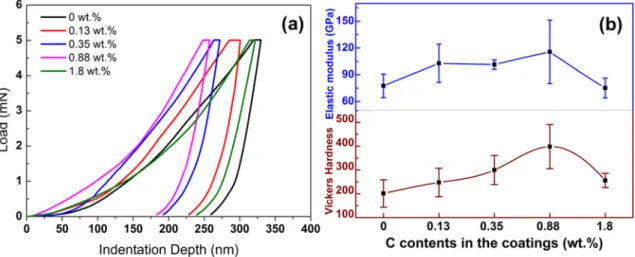
C atoms play an important role in improving the hardness of the Au Ni coating because all Au Ni/a C coatings with different C contents were observed to be harder than the Au Ni reference coating. From 0.13 wt% to 0.88 wt%, the residual indentation depth of the composite coating decreased with an increase in the C content, and the hardness of the Au Ni/a C composite coating with C content of 0.88 wt% reached 400 HV. However, the tendency of the coating hardness variation was reversed when the C content exceeded 0.88 wt%. Based on the Raman results, embedded in the Au Ni crystal lattice and accumulated as a C clusters are the two forms of C atoms in the composite coatings. As impurities, C atoms which are interstitially doped in the Au Ni crystal lattice can induce lattice strains, and as a result, a significant solid so lution strengthening effect was induced in the Au Ni coating. In addi tion, as confirmed by the TEM results, the crystal defects induced by the embedding of C clusters improved the hardness (dispersion strength ening). After reaching a plateau, the hardness of the Au Ni/a C com posite coating decreased with a further increase in C content. This phenomenon could be explained by the cluster size increase of the a C in the composite coatings that weakened the dispersion strengthening effect. A similar variation tendency of the elastic modulus as a function of C contents was also observed. In Au Ni/a C coatings, the residual stresses are compressive stresses, which decrease the interatomic dis tance and increase the stiffness of the interatomic bonding accordingly [44]. Therefore, compared to the Au Ni coating, the elastic modulus of Au Ni/a C (with C content of 0.88 wt%) increased from 77 GPa to 115 GPa. Again, the sudden decrease in the elastic modulus of the coating with C content of 1.8 wt% was due to the high volume content of a C phase.
Besides the residual stress and hardness, the adhesion performance of the Au Ni/a C coating on the CuCrZr substrate is also an essential factor for coating durability. As shown in Fig. 9, based on the SEM observation of the scratch tracks, all the Au Ni and Au Ni/a C coatings showed the typical ductile failure mode without the occurrence of chipping [45]. Three typical stages occurred on the scratch track on the Au Ni/a C composite coatings with C contents of 0.35 wt%, 0.88 wt%,
Fig. 7. Results of the coating residual stress measurement on the Si (100) wafer: (a). The curvature of the Si substrates. (b). Residual stresses of the deposited coatings with different C contents. (c). Schematic diagram of Ni atom-induced intrinsic tensile stress in the Au-Ni coating. (d). Schematic diagram of C atom-induced intrinsic compressive stress in the Au-Ni/a-C composite coatings.
and 1.8 wt%, which include a small plastic deformation stage, a transverse cracking stage, and a buckling and spallation stage. For the coatings without C and with a low C (0.13 wt%), no transverse cracking stages were observed, indicating that the cohesive strength of the Au Ni/a C coating decreased with increasing C content, i.e., the C con stituent decreased the toughness of the composite coating. However, all the coatings showed a high adhesive strength on CuCrZr substrates, and no distinct differences in their adhesive strengths were observed. The scratch critical loads of the coatings were approximately 30 N.
3.4. Electrical performance
For the electrical resistivity, a sudden increase of 1.7μΩ/cm oc curred on the Au Ni/a C coating with C content of 0.13 wt%, compared with the Au Ni reference (Fig. 10). Based on Raman analysis, in the Au
Ni/a C coating with C content of 0.13 wt%, C atoms were mainly al loyed in the Au Ni lattice. The lattice distortion caused by the embed ding of the C atoms could be the reason for the sudden increase in the electrical resistivity. With higher C contents, the generated a C nano clusters had a small effect on the electrical resistivity of the coating. These Au Ni/a C composite coatings have electrical resistivities ap proximately 8.2μΩ/cm, which are comparable to the electrical re sistivity of the magnetron sputtered pure Au coating (3.2μΩ/cm).
3.5. Tribological performance
Besides in typical atmospheric working environments, many sliding electrical contacts are applied under particular conditions, such as in a high vacuum. To evaluate the feasibility of applying the Au Ni/a C coatings developed as electrical/tribological functional coatings,
Fig. 8. Nanoindentation measurement results: (a). Load–displacement curves. (b). Vickers hardness and elastic modulus.
Fig. 9. Scratch test results: (a). Optical microscope image of the full scratch track on the coating sample with C content of 1.8 wt%. (b–f). SEM images of the scratch tracks from the coating samples with C contents of 0 wt%, 0.13 wt%, 0.35 wt%, 0.88 wt% and 1.8 wt%, respectively. (g). Critical loads of the coatings.
tribological tests were performed both under atmospheric and high vacuum (10−3Pa) conditions. As shown inFig. 11, under atmospheric conditions, without compounding a C, the Au Ni coating exhibits a large CoFfluctuation and the peak for CoF is approximately 0.3. As the carbon content increased from 0.13 wt% to 1.8 wt% in the composite coatings, CoF showed a slight downward trend owing to the solid lu bricating effect. The CoF of the coating containing 1.8 wt% C varied slightly, and its value was approximately 0.2. Although the differences in the CoF of the coatings with and without a C composites were low, the Au Ni/a C composite coatings, especially those with a high C con tent had a higher wear resistance. The wear rate of the Au Ni coating was 5.2 × 10⁻⁶mm3/N·m, and this value was minimized to
Fig. 10. Electrical resistivities of the deposited coatings.
Fig. 11. Tribological performance of the deposited coatings: (a, b). CoF and wear rate under atmospheric conditions. (c, d). CoF and wear rate at 10−3Pa vacuum.
2.2 × 10⁻⁶ mm3/N·m on the coating sample with C content of 1.8 wt%.
The lubricating function of a C is the dominant factor which minimizing the wear rate.
Because water vapor is a necessary component for reducing the bonding energy between the hexagonal planes of the graphite, the lu bricating efficiency of a C is low in high vacuum condition. As a result, the CoFs of all the coatings increased two times higher than in atmo sphere. The coating sample containing 1.8 wt% C still had a slight self lubricating function below 5500 cycles with a CoF of 0.4. However, in vacuum, the minimum wear rate was 4.5 × 10⁻⁶ mm3/N·m, which
occurred on the coating sample with C content of 0.35 wt%. In this case, lubrication was not the main factor determining the wear rate; the comprehensive effects of the coating hardness, residual stress, and toughness on the wear rate were more important.
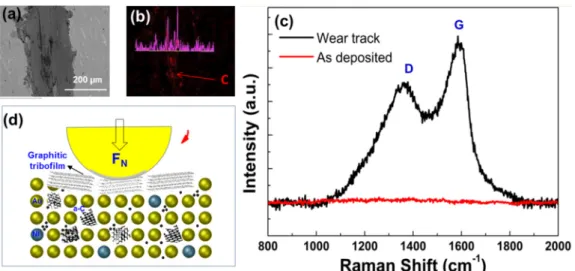
To understand the lubricating mechanism of the Au Ni/a C coating, the coating sample containing 0.13 wt% C was selected and wear track characterizations were conducted. As shown in Fig. 12 (b), C accumu lation in the wear track was verified through EDS mapping after sliding. Compared with the Raman spectrum of the coating as deposited, two pronounced peaks corresponding to the D and G peaks were observed at 1369 cm−1 and 1588 cm−1, respectively. The I
D/IG ratio was calculated
to be 0.83. This indicates that agglomeration of sp2 bond rich C oc
curred during sliding, i.e., a graphitic C tribolayer was generated and covered the wear track. As the schematic diagram shows in Fig. 12 (d), originally, C atoms distributed in the Au Ni/a C coating uniformly as free atoms in the Au Ni lattice or in the a C nanocrystallite with a high content of sp3 bonds. During sliding, accompanied by wear, C clusters
accumulated and possibly transferred between the ball and the coating. The pressure owing to the normal contact force and the annealing owing to friction could induce the graphitization process at local con tact areas [46]. The graphitic layer that developed between the two
original coating, the graphitization process was more significant, and as a result, the CoF was lowered.
4. Conclusion
In this study, Au Ni/a C coatings produced with different RF sput tering powers for the graphite target from 0 W to 400 W were deposited on CuCrZr substrates using the magnetron sputtering method. The coatings have a typical columnar structure and the smallest columnar size was achieved at 200 W. The highest content of C in the composite coating was approximately 1.8 wt%. We confirmed from the XPS and Raman results that the C clusters in the composite coatings are a C, and with an increase in the RF sputtering power, graphitization of C clusters was observed. Unlike electrodeposition, the magnetron sputtered Au Ni and Au Ni/a C coatings contain both fcc and hcp stacking structures, and more stacking faults were generated in the coating produced at the higher RF sputtering power. Compounding C in Au Ni significantly improved the mechanical performance. The coating sample containing 0.88 wt% C had the largest hardness, elastic modulus, and critical load, which were 400 HV, 115 GPa and 41.7 N, respectively. The toughness of the composite coatings decreased with an increase in the RF sput tering power; however, the electrical resistivity was not distinctly af fected, and the values were approximately 8μΩ/cm. The Au Ni/a C composite coatings show good wear resistance compared with the Au Ni coating under atmospheric conditions. For the composite coating containing 1.8 wt% C, the wear rate was 2.2 × 10⁻⁶mm3/N·m (less
than 50% of the Au Ni wear rate). However, in high vacuum, the ad vantages of composite a C in Au Ni were not distinct.
Acknowledgment
Part of this work was set up with funding support from National Magnetic Confinement Fusion Program of China under Contract No. 2014GB101000.
References
[1] L. Chalumeau, M. Wery, H. Ayedi, M. Chabouni, C. Leclere, Development of a new electroplating solution for electrodeposition of Au–Co alloys, Surf. Coat. Technol. 201 (2006) 1363–1372.
[2] T. Osaka, Y. Okinaka, J. Sasano, M. Kato, Development of new electrolytic and electroless gold plating processes for electronics applications, Sci. Technol. Adv. Mater. 7 (2006) 425–437.
[3] M. Hosseini, S. Ebrahimi, The effect of Tl (I) on the hard gold alloy electro-deposition of Au–Co from acid baths, J. Electroanal. Chem. 645 (2010) 109–114. [4] A. Shugurov, A. Panin, A. Lyazgin, E. Shesterikov, Fractal analysis of the evolution
of friction surfaces of galvanic AuNi coatings, Tech. Phys. Lett. 38 (2012) 484–487.
[5] G. Holmbom, B. Jacobson, J. Sundgren, Composition, Structure & Hardness of pulse-plated nickel-hardened goldfilms, Proc. of the AESF Annual Technical Conference. Baltimore, 1995.
[6] L. Chalumeau, M. Wery, H. Ayedi, M. Chabouni, C. Leclere, Application of a Doehlert experimental design to the optimization of an Au–Co plating electrolyte, J. Appl. Electrochem. 34 (2004) 1177–1184.
[7] Y. Wang, Y. Ju, S. Wei, W. Lu, B. Yan, W. Gao, Mechanical properties and micro-structure of Au–Ni–TiO2nano-composite coatings, Mater. Charact. 102 (2015)
189–194.
[8] Z. Chen, J. Hillairet, V. Turq, Y. Song, R. Laloo, J. Bernard, et al., Characterizations of thermal stability and electrical performance of Au-Ni coating on CuCrZr substrate for high vacuum radio-frequency contact application, Thin Solid Films 659 (2018) 81–88.
[9] A. Dolati, M. Ghorbani, M. Ahmadi, An electrochemical study of Au–Ni alloy electrodeposition from cyanide–citrate electrolytes, J. Electroanal. Chem. 577 (2005) 1–8.
[10] N. Yamachika, Y. Musha, J. Sasano, K. Senda, M. Kato, Y. Okinaka, et al., Electrodeposition of amorphous Au–Ni alloy film, Electrochim. Acta 53 (2008) 4520–4527.
[11] T. Yokoshima, A. Takanaka, T. Hachisu, A. Sugiyama, Y. Okinaka, T. Osaka, Mechanical and electrical properties of Au-Ni-C alloyfilms produced by pulsed current electrodeposition, J. Electrochem. Soc. 160 (2013) D513–D518. [12] P. Cavallotti, P. Cojocaru, L. Magagnin, Soft gold coatings: influence of additives
and pulse plating, Trans. IMF 90 (2012) 246–251.
[13] M. Alishahi, S.M. Monirvaghefi, A. Saatchi, S.M. Hosseini, The effect of carbon nanotubes on the corrosion and tribological behavior of electroless Ni–P–CNT composite coating, Appl. Surf. Sci. 258 (2012) 2439–2446.
[14] Y. Jeon, J. Byun, T. Oh, Electrodeposition and mechanical properties of Ni–carbon nanotube nanocomposite coatings, J. Phys. Chem. Solids 69 (2008) 1391–1394. [15] C.P. Kumar, T. Venkatesha, R. Shabadi, Preparation and corrosion behavior of Ni
and Ni–graphene composite coatings, Mater. Res. Bull. 48 (2013) 1477–1483. [16] S. Arai, M. Endo, Carbon nanofiber-copper composites fabricated by electroplating,
Electrochem. Solid-State Lett. 7 (2004) C25–C26.
[17] Y. Yang, M. Yan, Y. Zhang, C. Zhang, X. Wang, Self-lubricating and anti-corrosion amorphous carbon/Fe3C composite coating on M50NiL steel by low temperature plasma carburizing, Surf. Coat. Technol. 304 (2016) 142–149.
[18] S. Dub, Y. Pauleau, F. Thiery, Mechanical properties of nanostructured copper-hy-drogenated amorphous carbon compositefilms studied by nanoindentation, Surf. Coat. Technol. 180 (2004) 551–555.
[19] W. Gulbiński, S. Mathur, H. Shen, T. Suszko, A. Gilewicz, B. Warcholiński, Evaluation of phase, composition, microstructure and properties in TiC/aC:H thin films deposited by magnetron sputtering, Appl. Surf. Sci. 239 (2005) 302–310. [20] J. Sánchez-López, D. Martínez-Martínez, C. Lopez-Cartes, A. Fernández,
Tribological behaviour of titanium carbide/amorphous carbon nanocomposite coatings: from macro to the micro-scale, Surf. Coat. Technol. 202 (2008) 4011–4018.
[21] J. Sánchez-López, D. Martínez-Martínez, M. Abad, A. Fernández, Metal carbide/ amorphous C-based nanocomposite coatings for tribological applications, Surf. Coat. Technol. 204 (2009) 947–954.
[22] D. Liu, L. Zheng, Y. Liang, H. Li, J. Liu, L. Luo, et al., Preparation, biocompatibility, and biotribological properties of TiN-incorporated graphite-like amorphous carbon bio-ceramic compositefilms, Ceram. Int. 44 (2018) 6810–6816.
[23] D. Batory, M. Czerniak-Reczulska, L. Kolodziejczyk, W. Szymanski, Gradient tita-nium and silver based carbon coatings deposited on AISI316L, Appl. Surf. Sci. 275 (2013) 303–310.
[24] C. Corbella, E. Bertran, M. Polo, E. Pascual, J. Andújar, Structural effects of nano-compositefilms of amorphous carbon and metal deposited by pulsed-DC reactive magnetron sputtering, Diam. Relat. Mater. 16 (2007) 1828–1834.
Fig. 12. Wear track characterizations of the Au-Ni/a-C coating with C content of 0.13 wt%: (a). SEM image of the wear track. (b). EDS mapping of C in the area of (a). (c). Raman spectra in the wear track. (d). Schematic diagram of C lubricant tribofilm generation.
[25] M.Čekada, P. Panjan, D. Kek-Merl, M. Panjan, G. Kapun, SEM study of defects in PVD hard coatings, Vacuum 82 (2007) 252–256.
[26] P.E. Hovsepian, A. Ehiasarian, Y. Purandare, B. Biswas, F. Pérez, M. Lasanta, et al., Performance of HIPIMS deposited CrN/NbN nanostructured coatings exposed to 650 °C in pure steam environment, Mater. Chem. Phys. 179 (2016) 110–119. [27] E.O. Arregui, M. Caro, A. Caro, Numerical evaluation of the exact phase diagram of
an empirical Hamiltonian: embedded atom model for the Au-Ni system, Phys. Rev. B 66 (2002) 054201.
[28] Z. Yang, D.J. Lichtenwalner, A.S. Morris, J. Krim, A.I. Kingon, Comparison of Au and Au–Ni alloys as contact materials for MEMS switches, J. Microelectromech. Syst. 18 (2009) 287–295.
[29] H.-S. Zhang, J.L. Endrino, A. Anders, Comparative surface and nano-tribological characteristics of nanocomposite diamond-like carbon thinfilms doped by silver, Appl. Surf. Sci. 255 (2008) 2551–2556.
[30] L. Dubrovinsky, N. Dubrovinskaia, W. Crichton, A.S. Mikhaylushkin, S. Simak, I. Abrikosov, et al., Noblest of all metals is structurally unstable at high pressure, Phys. Rev. Lett. 98 (2007) 045503.
[31] X. Huang, S. Li, Y. Huang, S. Wu, X. Zhou, S. Li, et al., Synthesis of hexagonal close-packed gold nanostructures, Nat. Commun. 2 (2011) 292.
[32] A. Monshi, M.R. Foroughi, M.R. Monshi, Modified Scherrer equation to estimate more accurately nano-crystallite size using XRD, World J. Nano Sci. Eng. 2 (2012) 154–160.
[33] B.R. Jany, N. Gauquelin, T. Willhammar, M. Nikiel, K. Van den Bos, A. Janas, et al., Controlled growth of hexagonal gold nanostructures during thermally induced self-assembling on Ge (001) surface, Sci. Rep. 7 (2017) 42420.
[34] R.J. Yeo, Overview of Amorphous Carbon Films, Springer, Singapore, 2017. [35] L. Gu, P. Ke, Y. Zou, X. Li, A. Wang, Amorphous self-lubricant MoS2-C sputtered
coating with high hardness, Appl. Surf. Sci. 331 (2015) 66–71.
[36] P.K. Chu, L. Li, Characterization of amorphous and nanocrystalline carbonfilms,
Mater. Chem. Phys. 96 (2006) 253–277.
[37] P. Mandal, A.P. Ehiasarian, P.E. Hovsepian, Lubricated sliding wear mechanism of chromium-doped graphite-like carbon coating, Tribol. Int. 77 (2014) 186–195. [38] A.C. Ferrari, J. Robertson, Interpretation of Raman spectra of disordered and
amorphous carbon, Phys. Rev. B 61 (2000) 14095.
[39] F. Zhou, K. Fu, B. Liao, J. Yu, C. Yang, X. Zhang, Effect of carbon content on na-nostructural, mechanical and electrochemical characteristics of self-organized nc-ZrCN/a-CN × nanocompositefilms, Appl. Surf. Sci. 327 (2015) 350–357. [40] V. Teixeira, Residual stress and cracking in thin PVD coatings, Vacuum 64 (2002)
393–399.
[41] T.C. Totemeier, J. Wright, Residual stress determination in thermally sprayed coatings—a comparison of curvature models and X-ray techniques, Surf. Coat. Technol. 200 (2006) 3955–3962.
[42] P. Kadolkar, T.R. Watkins, J.T.M. De Hosson, B. Kooi, N.B. Dahotre, State of re-sidual stress in laser-deposited ceramic composite coatings on aluminum alloys, Acta Mater. 55 (2007) 1203–1214.
[43] F. Mao, M. Taher, O. Kryshtal, A. Kruk, A. Czyrska-Filemonowicz, M. Ottosson, et al., Combinatorial study of gradient Ag–Al thin films: microstructure, phase formation, mechanical and electrical properties, ACS Appl. Mater. Interfaces 8 (2016) 30635–30643.
[44] Y.-C. Huang, S.-Y. Chang, C.-H. Chang, Effect of residual stresses on mechanical properties and interface adhesion strength of SiN thinfilms, Thin Solid Films 517 (2009) 4857–4861.
[45] S. Bull, Failure modes in scratch adhesion testing, Surf. Coat. Technol. 50 (1991) 25–32.
[46] Z. Zhou, K. Li, I. Bello, C. Lee, S. Lee, Study of tribological performance of ECR–CVD diamond-like carbon coatings on steel substrates: part 2. The analysis of wear mechanism, Wear 258 (2005) 1589–1599.