HAL Id: tel-03191339
https://pastel.archives-ouvertes.fr/tel-03191339
Submitted on 7 Apr 2021HAL is a multi-disciplinary open access archive for the deposit and dissemination of sci-entific research documents, whether they are pub-lished or not. The documents may come from teaching and research institutions in France or abroad, or from public or private research centers.
L’archive ouverte pluridisciplinaire HAL, est destinée au dépôt et à la diffusion de documents scientifiques de niveau recherche, publiés ou non, émanant des établissements d’enseignement et de recherche français ou étrangers, des laboratoires publics ou privés.
Engineering and optimization of electrode/electrolyte
interfaces to increase solid oxide fuel cell (SOFC)
performances
Rossen Tchakalov
To cite this version:
Rossen Tchakalov. Engineering and optimization of electrode/electrolyte interfaces to increase solid oxide fuel cell (SOFC) performances. Materials. Université Paris sciences et lettres, 2021. English. �NNT : 2021UPSLM001�. �tel-03191339�
Préparée à MINES ParisTech
Engineering and optimization of electrode/electrolyte
interfaces to increase solid oxide fuel cell (SOFC)
performances
--
Ingénierie et optimisation des interfaces
électrode/électrolyte pour augmenter les performances de
piles à combustible à oxyde solide (SOFC)
Soutenue par
Rossen TCHAKALOV
Le 29 janvier 2021
Ecole doctorale n° 621
Ingénierie des Systèmes,
Matériaux, Mécanique,
Énergétique
Spécialité
Sciences et génie des
matériaux
Composition du jury :
Daria VLADIKOVA Présidente
Professeur,
Bulgarian Academy of Sciences
Jean-Claude GRENIER Rapporteur
Directeur de recherche émérite, ICMCB-CNRS
Paolo PICCARDO Rapporteur
Professeur, University of Genova
Marjorie CAVARROC Examinateur
Ingénieur Docteur, SAFRAN Tech
Anthony CHESNAUD Examinateur
Chargé de recherches, MINES ParisTech
Guilhem DEZANNEAU Co-Directeur de thèse Directeur de recherche, SPMS – CNRS
Alain THOREL Directeur de thèse
3 Thank you…
Many thanks to everybody who has made this work possible. Thanks to the great scientists for the basis of this wonderful and complex subject. Thanks to homo-sapiens for starting to work with ceramics almost 30 000 years ago, and making me feel like a monkey when I did not understand why the cells break.
I would like to humbly thank the members of the jury for their implication in my work, their time, their instructions and the discussion during the defense. Daria, thank you for your continuous encouragement and for being the best president. Paolo, thank you for the fun times but also for your serious work as rapporteur. Jean-Claude, thank you for accepting to be a part of my thesis even though my 250 pages almost scared you. I hope there was not too much “blabla”. Marjorie, thank you for your everlasting enthusiasm and your pieces of advice to improve my work. My thanks are extended to the other actors without who the defense would have been far more difficult, thank you Anne Françoise, Marie-Helene, Claudine Veronique, Lucien, Jerome, for your assistance and most of all for your patience.
My supervisors, my teachers, my guides, thank you from the bottom of my heart for your teachings. I have learned so much from you in both science but also human relations. You have always believed in me and coped with my “strong personality”. Alain, I was so happy to go to Bulgaria with you. You have been a bottomless well of knowledge and I am proud to have been your student. Anthony, you were the first pillar at the CdM and I will always cherish our coffees and discussions. Guilhem, you are one of the first to have believed in me and without you, I would not be writing this right now. You have been more than a teacher, you have been a friend and a father figure on so many occasions.
Thank you Jean-François and thank you Francesco for your help whenever it was needed and for your good mood. Thanks to all the wonderful people at Centre des matériaux to have made my work place a cozy place (Sylvain, Catherine, Zak, Yann, Vladimir, Vincent, Frank, Fabrice, Maria, Jean-Chris, Antoine, Kevin, Gérard, Lynh Thy Patrice, Greg, René, Vasco, Fred, Julie, Stephanie, Régis, Michel,…)
Thanks to all the wonderful people at Centrale who have accepted me as one of their own ever since my first day of internship before my thesis. Thank you for making me feel like at home
4 whenever I came to Centrale (Thierry, Christine V, Christine B, Pascale G, Pascale S, Pierre, Agnes, Brahim, Pierre Eymeric, Nicolas, Hubert, Charles, Raphaël, the late JMK, Vincent, Franz, Fabienne, Claire…)
Thanks to my PhD Buddies you have all been so great and I have grown so much with you. Thank you Sebo, Alex, Bastien, Jonathan, Jean-Mich, Patrizio, David, Hugo D, Ben, Amar, Chiraz, Vitoria, Chenyi, Milad, Henry… So much have been discussed, so many opinions have been shared, so much coffee has been drunk.
A special thanks to the BFF, Chloé and Lenny as well as Clément I would like to present to you my special thanks. Seeing you was one of the reasons to go to work with positive thinking. Thanks, friends.
Another special thanks to Hugo, the second-best co-bureau one may want ;). You were also one of my pillars during my thesis. We have followed each other’s Dunning–Kruger effect curves and we have evolved together. I hope we can both achieve our Ikagi and talk about it.
Thank you Erwan (Ewané), thank you for being my friend ever since the first year of University (It has been a while…) but particularly thank you for being there during the redaction, during the defense preparation, and finally during the presentation with me.
All my love and thanks to my new families. Christian, Corrine, Lucie, Quentin thank you for your interest in my work, your continuous support and your trust in me. Cedric, Naemi, Yoyo thank you for your love, and the happy times we have together. I am so happy that all our clans have merged.
To my Mom, my Bro and my Dad I can hardly express all my limitless gratitude. Your unconditional love, support, and trust are the only reason I am here today. I could always count on you have always made me feel special. Thank you…
To my muse, the love of my life, my partner, my better half. You have been next to me for every moment and I know now that we can confront every difficulty together. Every day is a blessing as long as I am with you. And thanks to your little C3 for the trips to work together.
6
Contents
General introduction ... 13
I. Sustainable development context ... 13
II. Energy and fuel cells ... 14
III. Project ... 16
Chapter I SOFC state of the art ... 22
I. Introduction ... 26
II. SOFC overview ... 26
II.A. Theoretical overview... 28
II.A.1. Free Gibbs energy and reversible potential ... 28
II.A.2. Irreversibilities and actual cell potential ... 29
II.B. SOFC composition ... 31
II.B.1. Electrolyte ... 31
II.B.2. Anode ... 34
II.B.3. Cathode ... 36
III. Bibliographic survey on performance enhancement for SOFCs ... 38
III.A. Materials and microstructure ... 39
III.A.1. Electrolyte ... 39
III.A.2. Anode ... 42
III.A.3. Cathode ... 47
III.B. Cell design ... 50
III.B.1. DM-Cell ... 50
III.B.2. Interfaces active surface area extension ... 51
IV. Objectives ... 52
IV.A. Fabrication ... 54
7
IV.C. Modeling ... 55
IV.D. Results and discussion ... 55
CHAPTER II Fabrication of planar and architectured SOFCs ... 67
I. Introduction ... 75
II. Raw materials ... 78
II.A. Powders ... 78 II.A.1. NiO ... 79 II.A.2. YSZ ... 82 II.A.3. CGO ... 85 II.A.4. LSM ... 86 II.A.5. LSCF ... 88
II.A.6. Pore former ... 89
II.B. Solvent and additives ... 90
II.B.1. Solvent ... 90
II.B.2. Dispersant ... 91
II.B.3. Binder ... 91
II.B.4. Plasticizer ... 92
III. Cell fabrication ... 92
III.A. Slurry ... 92
III.A.1. Preparation ... 92
III.A.2. Characterization ... 93
III.B. Tape casting ... 95
III.B.1. Equipment ... 96
III.B.2. Preliminary considerations – drying, shrinkage ... 96
8
III.B.4. Cathode casting ... 99
III.C. Architecturing and shaping ... 99
III.C.1. Laser engraving ... 100
III.C.2. Soft template architecturing ... 101
III.C.3. Tapes cutting ... 102
III.D. Thermal treatment ... 102
III.D.1. Additives elimination ... 102
III.D.2. Sintering ... 104
III.E. Cathode deposition ... 107
IV. Protocol validation and discussion ... 108
IV.A. Cell integrity ... 108
IV.A.1. Surface control ... 108
IV.A.2. Layer cohesion ... 109
IV.B. Functionality ... 111
V. Conclusion ... 113
VI. Bibliography ... 114
CHAPTER III Components characterization and architecture analysis ... 117
I. Introduction ... 125
II. Component characterization ... 126
II.A. Method ... 126
II.A.1. Layer thickness measurement ... 126
II.A.2. Average grain size assessment ... 126
II.A.3. Porosity characterization ... 127
II.A.4. Chemical distribution ... 128
9 II.B.1. Electrolyte ... 130 II.B.2. Anode ... 132 II.B.3. Cathode ... 134 II.B.4. Overview ... 136 II.C. Type II ... 137
II.C.1. Electrolyte and barrier layer ... 138
II.C.2. Anode ... 142
II.C.3. Cathode ... 144
II.C.4. Overview ... 146
III. Interface characterization ... 146
III.A. Method ... 146
III.B. Results ... 149
III.B.1. Soft template architecturing ... 149
III.B.2. Laser engraving of green tapes ... 160
IV. Conclusion and discussion ... 162
IV.A. Components ... 162
IV.A.1. Type I cells ... 163
IV.B. Type II cells ... 164
IV.C. Architecturation ... 164
CHAPTER IV – SOFC characterization and performance analysis ... 168
I. Introduction ... 178
II. Analysis methods and set-up ... 178
II.A. I/V ... 178
II.B. Electrochemical Impedance Spectroscopy (EIS) ... 179
10
II.B.2. Relative Gap method (R.G.) – a simplified comparison technique... 183
II.C. Measurement set-up ... 186
III. Results ... 187
III.A. Type I ... 188
III.A.1. Components reminder ... 188
III.A.2. I/V ... 190
III.A.3. EIS ... 196
III.B. Type II ... 206
III.B.1. Components reminder ... 206
III.B.2. I/V ... 208
III.B.3. EIS ... 213
IV. Overview, conclusion and perspectives ... 223
IV.A. Analysis methodology ... 223
IV.B. Type I cells ... 224
IV.C. Type II cells ... 224
IV.D. Conclusion ... 225
IV.E. Perspectives ... 225
CHAPTER V ... 229
Overview, Conclusion and perspectives ... 229
I. Introduction ... 234
II. Fabrication protocol and characterization ... 234
II.A. Fabrication protocol ... 234
II.B. Architecturing ... 236
II.C. Type I cells ... 240
11
II.E. Conclusion ... 243
III. Electrochemical analysis ... 244
III.A. Method ... 244
III.B. Type I cells ... 245
III.C. Type II ... 247
IV. General conclusion ... 249
V. Perspectives ... 250
V.A. Complementary experiments ... 250
V.B. Durability test ... 250
V.C. Ideal cell/ Rigel application ... 251
V.D. Modeling ... 251
I. Fuel Cell types ... 254
II. SOFC configurations ... 255
III. Slurries composition ... 257
III.A. Anode ... 257
III.B. Electrolyte and barrier ... 257
12
Abbreviations
AEC Area Expansion Coefficient MEK MethylEthylKetone
AFC Alkaline fuel cell MEKET MEK+EtOH
AS Anode Support MeOH Methanol
ASR Area Specific Resistance MIEC mixed ionic and electric conductor ATPB Active Triple Phase Boundary OCV Open circuit voltage
BM Ball milling ORR oxygen reduction reaction
B-V. Buttler Volmer PAFC Phosphoric acid fuel cell
cermet Ceramic-metallic composite PCFC Proton Conducting Fuel Cell
CGO Gadolinium doped ceria PEG PolyEthileneGlicol
DGM Dusty gas model PEMFC Proton exchange membrane fuel cell
DMFC Direct methanol fuel cell PET PolyEthileneTaftalate EDS Energy Dispersive X-ray Spectroscopy PVB PolyvinylButiral EFCF European Fuel Cell Forum R.G. Relative Gap
EIS Electrochemical impedance spectroscopy SDC Scandium Doped Ceria
EMF Electromotive force SEM Scanning electron microscopy
EtOH Ethanol SOFC Solid oxide fuel cell
HT High Temperature TEC Thermal expansion coefficient
IPCC Intergovernmental Panel on Climate
Change TEM Transmission electron microscopy
IT Intermediate Temperature TGA ThermoGravimetric Analysis LSCF Lanthanum strontium cobalt ferrite TPB Triple Phase Boundary LSM Lanthanum strontium manganite UNEP United Nations Environment
Program
LST Lanthanum strontium titanate YST Yttrium strontium titanate
LT Low Temperature YSZ Yttrium stabilized zirconia
13
General introduction
Contents
I. Sustainable development context ... 13 II. Energy and fuel cells ... 14 III. Project ... 16
I.
Sustainable development context
In the past five decades, researchers have widely studied the impact of human activity on the environment and in particular on climate change which has been a global concern since the first world summit. This concern has resulted in the creation of the United Nations Environment Program (UNEP) in 1972 establishing laws and guidelines to tackle the pollution caused by the industrialization of the 20th century [1]. Another important milestone reflecting the will to limit the impact of human activity on the environment is the creation of the Intergovernmental Panel on Climate Change (IPCC - United Nations body for assessing the science related to climate change) in the late 80s [2], providing regular scientific assessments as well as adaptations and mitigation options. Those organisms are some of the numerous initiatives taken in order to control the human and limit footprint on the environment [3] [4] [5] [6].
However, the recent climate predictions [7] reveal that even further changes must be made. Several scenarii have been developed, anticipating the consequences of a global temperature increase and any rising above 1,5°C would have a dramatic impact on a planetary scale. Desertification, ice melting, and species extinction are some of the already observed phenomena [8] [9] [10].
With the world population growth [11] as well as the improvement of the global standards of living, the energy demand is increasing at a dramatic rate. The worldwide global energy consumption has increased by more than 70% in less than 30 years (120% increase worldwide electricity consumption) [12]. Despite the strive to reduce carbon dioxide and the emission of
14 other, the energy mix remains still highly dependent on fossil resources like coal, oil, or gas as well as uranium for nuclear energy. The dependency on fossil fuels or uranium also creates potential geopolitical tensions due to their uneven distribution. This context reveals the unprecedented urgency for green sustainable energy production, storage, and distribution.
In this context, the “power to gas” concept and more precisely the utilization of hydrogen gas as an energy vector is receiving a lot of interest in nowadays society. The development of fuel cell and electrolyzer technology has been strongly supported by governmental and private aids around the world in order to promote renewable energy storage and hydrogen-fueled mobility. Companies such as McPhy have seen their stock price multiplied in several months in 2020 and have attracted a multitude of contracts for hydrogen mobility [13] and green hydrogen production [14], despite the global economic crisis due to the Covid19 pandemic. Air Liquide has stared in 2016 their program Blue Hydrogen “whose goal is to gradually decarbonize its production of hydrogen dedicated to energy applications” [15] and have ever since participated in the development of hydrogen mobility [16] [17].
II.
Energy and fuel cells
As mentioned in the previous paragraph, the production of green hydrogen and its utilization as fuel requires electrochemical devices such as electrolyzers and fuel cells. In this work, we will concentrate on fuel cell operation, but it is interesting to note that an electrolyzer can be compared to a fuel cell functioning in reverse.
A fuel cell is an electrochemical device allowing the direct conversion of electrochemical energy, provided from the oxidation of a reacting compound used as fuel into electrical energy and heat. Because there is no combustion process involved, fuel cells are not limited by Carnot efficiency and can reach higher efficiency values than thermal engines. Furthermore, the electrical work is directly converted from the reaction enthalpy, thus reducing the number of transformations and consequently reducing energy losses.
Sir William Robert Grove, is one of the first scientists to study the chemistry behind fuel cells functioning by demonstrating water dissociation and formation in his “gas voltaic battery” (Figure 1). In the first half of the 19th century, Grove showed that steam can be dissociated into
15 Hydrogen and Oxygen by electrolysis and that this process is reversible. Ever since fuel cell technology has attracted considerable interest [18].
Figure 1 Sir William Robert Grove's "gas voltaic battery" [23]
High power fuel cell systems and stacks have been built in the 1920s by William W. Jacques and Emil Baur reaching 30 kW [19]. Practical applications development started in the 30s by Thomas Francis Bacon whose fuel cells were to be used in the Royal Navy’s submarines during the second world war. In 1958, Bacon presented his alkaline fuel cells which, thanks to their reliability, attracted the attention of the company Pratt and Whitney and were installed aboard the Apollo spacecraft. It was at the same time that GE also developed fuel cell technology for NASA and McDonnell Aircraft during the GEMINI program. They also provided the fuel cell for one of the first fuel cell-powered vehicles: a 15 kW tractor from Allis Chalmers (figure 2 and [20]). In the 60s different types of fuel cells, such as solid oxide fuel cells (SOFC) [21] (cf. ANNEX - I) have started to emerge changing the operating temperature, component materials, and fuel. Since then development has continued taking into account an increase in power density and durability, as well as lowering costs. In the 21st-century fuel cells have been integrated into numerous domains, especially in transportation (automobiles, buses, tractors, trains, and ships) and stationary use (homes, hospitals, schools, etc.) [22].
16 Figure 2 Allis Chalmers fuel cell tractor (source image: Smithsonian institute [24])
In this study, we will focus on SOFC technology which attracts a lot of interest due to several advantages compared to other types of fuel cells. The use of oxide ceramic materials reduces drastically corrosion issues and inconveniences linked to the management of liquid electrolytes. The high temperature boosts electrode kinetics, thus allowing to achieve high power densities with low to none use of noble catalysts such as Pt. Moreover the high-quality heat allows to perform internal reforming making the utilization of carbon-based gases as fuel possible and highly efficient compared to their use in thermal engines. The heat can also be coupled with other technologies, thus increasing the efficiency of the fuel cells by cogeneration. However, SOFC presents some important disadvantages such as relatively low durability (several tens of thousands of hours) induced by the high-temperature operation as well as electrode material alteration or poisoning.
III.
Project
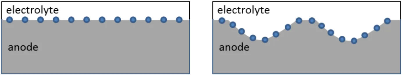
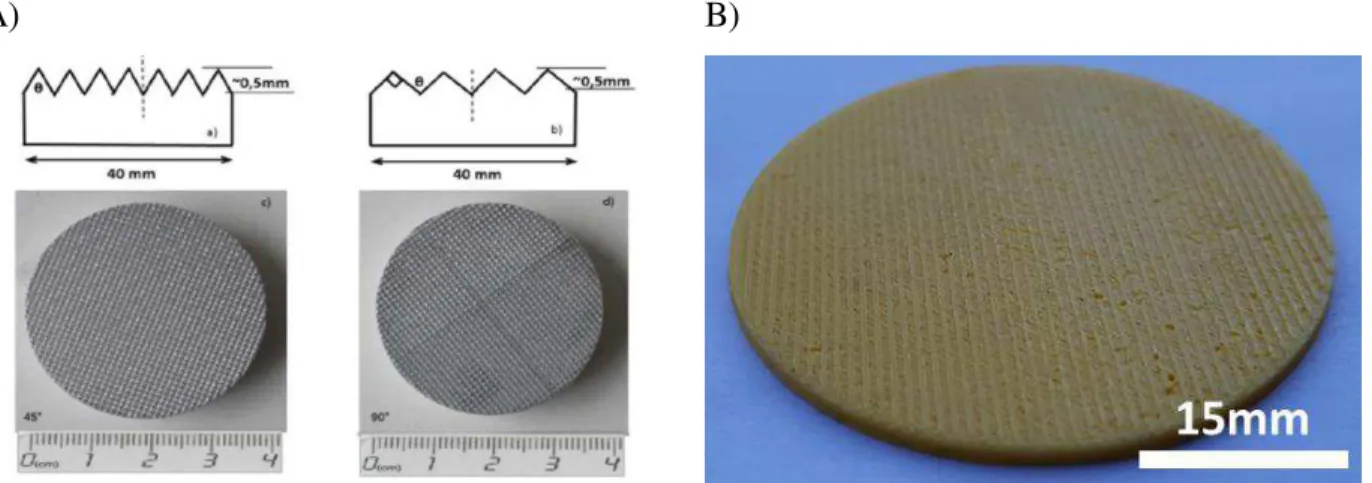
Our general objective is to enhance the electrochemical performances (current and power density) of a single solid oxide fuel cell by engineering geometrically macroscale architectured electrode/electrolyte interfaces (fig 2), thus expanding the equivalent exchange surface area. This expansion should develop a larger number of active triple phase boundaries (ATPB), allowing to sustain more simultaneous electrochemical reactions, resulting in an increase in power density. A
17 previous study confronts experimental data with numerical simulation and brings forward an underestimation of the power increase calculated by the numerical model [28] [29].
Figure 3 Concept
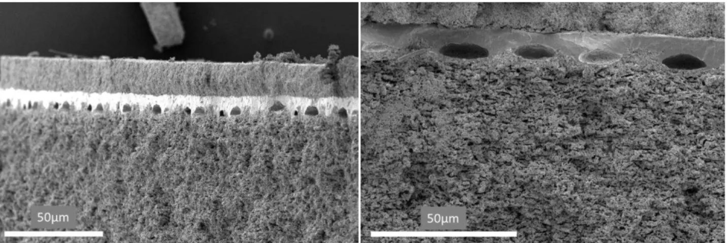
This work is conducted following three axes: fabrication, structural characterization. A low cost and reproducible fabrication protocol for anode supported button cells with planar or architectured electrode/electrolyte interfaces are established using common ceramics engineering techniques such as tape casting. Structural analyses are performed using scanning electron microscopy (SEM), using secondary and backscattered electrons for the microstructural assessments as well as the measurement of the layers thicknesses and integrity observations, and dispersive X-ray spectroscopy for the chemical distribution and singularity analysis. Electrochemical measurements like electrochemical impedance spectroscopy (EIS) and polarization curves analysis are conducted to control the performances and compare the architectured cells to equivalent planar ones.
In the first chapter of this document, some general information such as basic fuel cell principles, types, and materials are reviewed. This is followed by a discussion on different potential pathways to increase SOFC performances such as interface architecting, supported by a brief bibliographic survey on the subject. In this chapter, a technical discussion on the project objectives will be conducted. The second chapter offers a detailed presentation of the fabrication protocol, as well as its validation. The third chapter is dedicated to the structural and microstructural analysis of the cells including porosity and layer thickness. The fourth chapter is focused on electrochemical measurements in order to characterize the fabricated fuel cells. Here fuel cells with architectured electrode/electrolyte interfaces are compared to equivalent planar cells and a discussion on the influence of the architecture is proposed. Finally, a discussion on the obtained results as well as the perspectives will be carried out.
18 References
[1] U. N. E i o e t, UNEP , UN Environment. http://www.unenvironment.org/node (accessed Aug. 20, 2019).
[2] IPCC — I te go e e tal Pa el o Cli ate Cha ge . https://www.ipcc.ch/ (accessed Aug. 20, 2019).
[3] What is the K oto P oto ol? | UNFCCC . https://u f .i t/k oto_p oto ol a essed Aug. , 2019).
[4] COP , Gouvernement.fr. https://www.gouvernement.fr/en/cop21 (accessed Aug. 20, 2019). [5] UNITED NATIONS Cli ate Cha ge Su it . https:// .u .o g/e / li ate ha ge/ a essed Aug. 20, 2019).
[6] Cli ate ha ge i itiati es a d pa t e ships , UNEP. http://www.unenvironment.org/explore-topics/climate-change/about-climate-change/climate-change-initiatives-and-partnerships (accessed Aug. 21, 2019).
[7] Glo al Wa i g of .5 oC — . https:// .ip . h/s 5/ a essed Aug. , 9 .
[8] Ma ti , UN Repo t: Natu e s Da ge ous De li e U p e ede ted ; Spe ies E ti tio Rates A ele ati g , United Nations Sustainable Development, May 06, 2019. https://www.un.org/sustainabledevelopment/blog/2019/05/nature-decline-unprecedented-report (accessed Aug. 20, 2019).
[9] A ti Sea I e Ne s a d A al sis | Sea i e data updated dail ith o e-da lag . https://nsidc.org/arcticseaicenews/ (accessed Aug. 20, 2019).
[10] La d a d D ought | UNCCD . https:// .u d.i t/issues/la d-and-drought (accessed Aug. 20, 2019).
[11] Wo ld Populatio P ospe ts - Population Division - U ited Natio s . https://population.un.org/wpp/Graphs/Probabilistic/POP/TOT/900 (accessed Aug. 20, 2019).
19
[12] Wo ld E e g Co su ptio Statisti s | E e data . https:// ea ook.e e data. et/total-energy/world-consumption-statistics.html (accessed Aug. 20, 2019).
[13] Nou eau o t at - Mobilité hydrog e , McPhy, Jul. 30, 2020. https://mcphy.com/fr/communiques/nouveau-contrat-mobilite-hydrogene/ (accessed Aug. 24, 2020).
[14] Nou eau o t at | Statio s et le t ol seu g a de apa it , McPhy, Aug. 03, 2020. https://mcphy.com/fr/communiques/nouveau-contrat-stations-et-electrolyseur-grande-capacite/ (accessed Aug. 24, 2020).
[15] H d oge e e g , Air Liquide, Apr. 28, 2016. https://www.airliquide.com/science-new-energies/hydrogen-energy (accessed Aug. 24, 2020).
[16] L e gie h d og e pou les hi ules , Air Liquide Energies, Dec. 12, 2016. https://energies.airliquide.com/fr/transport-propre-transport-passagers/lenergie-hydrogene-vehicules (accessed Aug. 24, 2020).
[17] Ai Li uide a o st ui e la p e i e statio h d og e haute p essio desti ... https://fr.media.airliquide.com/actualites/air-liquide-va-construire-la-premiere-station-hydrogene-haute-pression-destinee-aux-camions-longue-distance-en-europe-6776-1ba6d.html (accessed Aug. 25, 2020).
[18] J. M. Andúja a d F. Segu a, Fuel ells: Histo a d updati g. A alk alo g t o e tu ies , Renewable and Sustainable Energy Reviews, vol. 13, no. 9, pp. 2309–2322, Dec. 2009, doi: 10.1016/j.rser.2009.03.015.
[19] C. Sto e a d A. E. Mo iso , F o u iosit to po e to ha ge the o ld® , Solid State Ionics, vol. 152–153, pp. 1–13, Dec. 2002, doi: 10.1016/S0167-2738(02)00315-6.
[20] Allis-Chal e s Fuel Cell T a to , National Museum of American History. https://americanhistory.si.edu/collections/search/object/nmah_687671 (accessed Aug. 22, 2019). [21] J. Weiss a t a d R. Ruka, A Solid Ele t ol te Fuel Cell , J. Electrochem. Soc., vol. 109, no. 8, pp. 723–726, Jan. 1962, doi: 10.1149/1.2425537.
[22] Fuel Cell Appli atio s - a o e ie | S ie eDi e t Topi s . https://www.sciencedirect.com/topics/engineering/fuel-cell-applications (accessed Aug. 22, 2019).
20
[23] P. G. G i es, Histo i al path a s fo fuel ells , IEEE Aerospace and Electronic Systems Magazine, vol. 15, no. 12, pp. 7–10, Dec. 2000, doi: 10.1109/62.891972.
[24] Ho e , Smithsonian Institution. https://www.si.edu/home (accessed Aug. 22, 2019).
[25] O. Z. Sha af a d M. F. O ha , A o e ie of fuel ell te h olog : Fu da e tals a d appli atio s , Renewable and Sustainable Energy Reviews, vol. 32, pp. 810–853, Apr. 2014, doi: 10.1016/j.rser.2014.01.012.
[26] G. Che , Y. Gao, Y. Luo, a d R. Guo, Effe t of A site defi ie of LSM athode o the ele t o he i al pe fo a e of SOFCs ith sta ilized zi o ia ele t ol te , Ceramics International, vol. 43, no. 1, Part B, pp. 1304–1309, Jan. 2017, doi: 10.1016/j.ceramint.2016.10.082.
[27] S. C. Si ghal, Solid O ide Fuel Cells: Past, P ese t a d Futu e , i Solid Oxide Fuels Cells: Facts and Figures: Past Present and Future Perspectives for SOFC Technologies, J. T. S. Irvine and P. Connor, Eds. London: Springer London, 2013, pp. 1–23.
[28] M. Geagea, Nou elles a hite tu es de su fa es d ha ges de piles à o usti le de t pe SOFC pou l a lio atio de l effi a it le t o hi i ue , Ap . 7, A essed: Aug. 23, 2019. [Online]. Available: https://pastel.archives-ouvertes.fr/tel-01901236.
[29] F. Dello o a d M. Vi ia i, Si ulatio stud a out the geo et of ele t ode-electrolyte contact i a SOFC , Journal of Electroceramics, vol. 29, no. 3, pp. 216–224, Nov. 2012, doi: 10.1007/s10832-012-9766-8.
22
Chapter I
23
Chapter I abstract
The first chapter of this document is dedicated to a bibliographic study of the results of theoretical and experimental research on SOFCs' operation, of interest for the present study. In the first part, the basic principles of the fuel cells are presented including thermodynamics and electrochemistry overview. A simplified schematics of a SOFC allows visualizing the global cell operation, displaying the electrochemical reactions in each electrode, the gas diffusion, and charge transport directions (figure I – abstract – 1). In the second and the third part of the chapter, we present a brief literature review on the used materials and microstructures as well as on the different possibilities to increase the electrochemical performances of SOFC.
In the present work we propose a geometrical modification of the electrode/electrolyte interfaces to extend the apparent exchange surface and by doing so to increase the number and length of active triple phase boundaries as shown in Figure I – abstract - 2. There is also a potential activation of previously nonpercolating paths, therefore increasing the further the TPB density and length. Thus, the catalytic properties of the interface are modified (compared to a planar interface) and the activation losses, as well as the ohmic losses, should decrease.
Chapitre I re sume
Le premier chapitre de ce document est consacré à une étude bibliographique des résultats de la recherche théorique et expérimentale concernant le fonctionnement des SOFC, d'intérêt pour la réalisation de l'étude.
Dans la première partie, les principes de base des piles à combustible sont présentés, y compris relevant de la thermodynamique et de l'électrochimie. Un schéma simplifié d'une SOFC permet de visualiser le fonctionnement global de la pile, en affichant les réactions électrochimiques dans chaque électrode, la diffusion des gaz et les directions de transport de la charge (figure I - abstract - 1). Dans les deuxième et troisième parties du chapitre, nous présentons une brève revue de la littérature sur les matériaux utilisés et les microstructures, ainsi que sur les différentes possibilités d'augmenter les performances électrochimiques des SOFC.
24 Dans le présent travail, nous proposons une modification géométrique des interfaces électrode/électrolyte afin d'étendre la surface d'échange apparente et, ce faisant, d'augmenter le nombre et la longueur de frontières de triple phase actives, comme le montre la figure I - abstract - 2. Il y a également une activation potentielle de chemins précédemment non percolants, augmentant ainsi d'autant la densité et la longueur des TPB. Ainsi, les propriétés catalytiques de l'interface sont modifiées (par rapport à une interface plane) et les pertes d'activation, ainsi que les pertes ohmiques, devraient diminuer.
Figure I – abstract – 1 SOFC concept
25
Chapter I SOFC state of the art
Contents
I. Introduction ... 26 II. SOFC overview ... 26 II.A. Theoretical overview... 28 II.A.1. Free Gibbs energy and reversible potential ... 28 II.A.2. Irreversibilities and actual cell potential ... 29 II.B. SOFC composition ... 31 II.B.1. Electrolyte ... 31 II.B.2. Anode ... 34 II.B.3. Cathode ... 36 III. Bibliographic survey on performance enhancement for SOFCs ... 38 III.A. Materials and microstructure ... 39 III.A.1. Electrolyte ... 39 III.A.2. Anode ... 42 III.A.3. Cathode ... 47 III.B. Cell design ... 50 III.B.1. DM-Cell ... 50 III.B.2. Interfaces active surface area extension ... 51 IV. Objectives ... 52 IV.A. Fabrication ... 54 IV.B. Cell characterization and electrochemical testing ... 54 IV.C. Modeling ... 55 IV.D. Results and discussion ... 55
26
I.
Introduction
In this chapter, we will review some general information such as basic fuel cell principles, types and materials as well as different potential pathways to increase SOFC performances. A condensed bibliographic survey will accompany the latter. SOFC are a type of cells composed entirely of solid materials and which operate at high temperatures (600°C -1000°C). This technology has attracted significant interest over the past few decades, due to its elevated current and power densities, superior efficiency thanks to the cogeneration of electricity and high-quality heat, as well as its capacity to internally reform methane and other carbon-based fuels. Those are some of the reasons for which SOFC presents an ideal candidate for high energy output needs as in industry or housing application as well as heavy transportation.
The development of SOFC technology debuted in the late 1930s with the work on ion-conducting oxides of Emil Bauer and Hans Preis. Their work was based on earlier studies made by Walther Nernst on ceramics material composed of 85% ZrO2 and 15% Y2O3 also called “Nernst Mass”.
Since then the subject has known moderate advancement, but the high electrical resistance of the used materials, as well as the mechanical and the thermal-induced complications, have limited the research and development expansion. The Westinghouse’s cathode-supported tubular SOFC became one of the first SOFC power systems in the 80s and 90s. Since the SOFC development and commercialization has gained considerable attention. The research and application progress has been covered on multiple occasions in books and publications [1], and conferences, symposia, and conferences such as the European Fuel Cell Forum (EFCF [2]).
II.
SOFC overview
The functioning of a solid oxide fuel cell is equivalent to that of other types of fuel cells where the electrochemical energy from fuel oxidation (equation I-1) is directly transformed into electrical current. A single cell is composed of three principal compartments: two porous electrodes in which the redox reactions occur (equations I-2 and I-3), separated by a dense, ion-conducting electrolyte (figure I-3). The high operating temperature is necessary to activate the ion conduction of the electrolyte. The latter is dense and electrically insulating, to avoid gas and electronic short circuit. Thus the electrons are exchanged through an external circuit which results in an electrical current generation.
27 Figure I - 3 SOFC concept
One of the SOFC advantages is the capacity to use carbon-based gases as fuel (eq I-2 b and d). The reaction with methane is particularly efficient because of the intern reforming (eq. I-2c) producing in situ two supplementary fuels. Using fuel cells to generate electricity from methane has a notable advantage over combustion-based technologies as mentioned earlier, due to the lack of Carnot efficiency limitation. Its use, however, is associated with greenhouse gas emissions (CO2) and it can provoke carbon coking which is one of the principal anode degradations
mechanisms. + ↔ (I-1) + −↔ + − (I-2a) 𝐶 + − ↔ 𝐶 + + − (I-2b) 𝐶 + ↔ 𝐶 + (I-2c) {𝐶 + − ↔ 𝐶 + − + − ↔ + − (I-2d)
28
+ − ↔ − (I-3)
In this work, we will focus on the utilization of hydrogen gas as a fuel.
II.A. Theoretical overview
II.A.1. Free Gibbs energy and reversible potential
As the basic principle of operation is the transformation of internal electrochemical energy, a focus on the thermodynamic aspect is necessary. Every chemical reaction is associated with a free Gibbs energy depending on the chemical activities of the components as well as their chemical bond energy, and the operation conditions (eq I-4).
∆ = ∆ + × ( 𝑥) (I-4) Where ∆ is the standard Gibbs energy calculated by using the gas formation energy at atmospheric pressure, R is the gas constant, T is the operating temperature, 𝑥 and are respectively the oxidant and reducer activities.
The electrical potential of the reaction is proportional to the free Gibbs energy and depends on the number of exchanged electrons (eq I-5). By developing this expression, we obtain the Nernst relation, which allows expressing the system's electrical potential or its electromotive force as a function of the gas concentration i.e. partial pressure (eq I-6).
= −∆ (I-5)
= + × ( 𝐻
𝐻 , ) (I-6)
Where Erev is the reversible potential E°rev is the standard reversible potential, Pi is the partial
29 In the case of water vapor formation the reversible potential is: = . 𝑉 at 800°C with the use of humidified hydrogen as a fuel (pH2=0.97 bar, pH2O=0.03 bar) and air as oxygen source
(pO2=0.2 bar).
II.A.2. Irreversibilities and actual cell potential
Thermodynamics provides an insight into the behavior of a system in an equilibrium state. Within the fuel cell, a multitude of electrical, chemical, and diffusion processes occur while it is operating. Each of them influences the global electrical generation impacting the cell voltage by inducing irreversibility causing it to decline as the current increases. Outside the equilibrium, the notion of overpotential η is introduced (Equation I-7) to characterize the potential losses in the fuel cell.
𝜂 = − (I-7)
Those losses can be resumed in four principal categories which allow establishing the polarization equation (eq I-8) :
- Fuel cross-over and internal currents - Activation losses
- Ohmic losses
- Concentration losses
= − 𝜂 , − 𝜂 , − 𝜂 − 𝜂 , − 𝜂 , (I-8)
Where E is the actual cell voltage, 𝜂 , is the anode activation overpotential, 𝜂 , is the
cathode activation overpotential, 𝜂 is the polarization overpotential, 𝜂 , is the anode
concentration overpotential and 𝜂 , is the cathode concentration overpotential.
II.A.2.a) Activation losses
The activation overpotential is caused by the energy requirements to initiate the electrochemical reactions and more precisely, by the reduction kinetics at the anode and the sluggishness of the ORR at the cathode. At low current density, it is the predominant factor for voltage losses and it follows the Butler-Volmer equation (equations I-9 and I-10).
30 = , ∗ [
𝛼
𝐹 𝜂𝑎𝑐𝑡,𝑒 + − −𝛼𝐹 𝜂𝑎𝑐𝑡,𝑒] (I-9)
𝜂 , = −𝛼 ∗ ∗ ln∗ ( , ) +𝛼 ∗ ∗ ln∗ (I-10)
Where j0 is the exchange current density rate, j is the current density, α is the charge transfer
coefficient. The subscript “el” designates the considered electrode and j0, as well as α, depend on
the electrode material, microstructure, and chemical activity.
II.A.2.b) Ohmic losses
Provoked by internal resistance majorly due to the electrolyte ionic transportation resistance, as well as interface contact resistance and also hindered electronic conductivity in the electrodes. Thus, an equivalent series resistance is considered and used in ohmic low as shown in equation I-11.
𝜂 = ℎ × (I-11)
Where ℎ is the total cell resistance including ionic resistance of the electrolyte but also of the electrodes, electronic, and contact resistance.
II.A.2.c) Concentration losses
Concentration losses are caused by the decrease in the concentration of the reacting gasses, due to an insufficient gas supply rate in respect to their consumption. Hence, concentration losses are predominant at high current densities and it is possible to define a limiting current corresponding to the supply rate.
𝜂 , = − ∗ ln∗ ( − ) I-12
Where is the limiting current defined as the current where the partial pressure of the considered gas becomes zero as in equation I-14:
31
II.A.2.d) Polarization curve
Combining equations I- (8,9,11 and 12) we can plot the polarization curve of the fuel cell as shown in figure I – 4. We distinguish three domains on the curve where one of the overpotentials is predominant.
Figure I - 4 Typical polarization curve with the contributions corresponding to the activation, ohmic and concentration overpotentials
II.B. SOFC composition
As mentioned previously, a single fuel cell is generally composed of a porous anode and cathode separated by a dense electrolyte. Each component has a different role and its materials and microstructure must be adapted to ensure an optimal cell operation.
In this work, two types of fuel cells (Type I and type II cells) are fabricated differentiated by their electrolyte and electrode compositions.
II.B.1. Electrolyte
II.B.1.a) Definition
The term “Solid Oxide Fuel Cell” is derived from the utilization of a solid oxide material for the electrolyte. This component ensures the gas and electronic separation of the electrodes as well as
32 the ionic transfer necessary to preserve the electroneutrality of the cell. Its position in contact with both a reducible atmosphere at the anode side and an oxidizing atmosphere at the cathode side imposes excellent chemical stability. Thus, the electrolyte has very strict requirement specifications:
- Thermal and chemical stability in reducing and oxidizing atmospheres - Good ionic conductivity and negligible electronic conductivity
- Dense microstructure
- Thermal and chemical compatibility with both electrodes
Oxygen ion transport in most oxide electrolyte materials is carried out through lattice oxygen vacancies. The specific ion conductivity (S/cm) is influenced by the concentration of those vacancies. Generally fluorite or perovskite oxides with low valence element substitution (also called doping), present increased vacancy concentration due to the Van der Waals potential mismatch between the cations (Figure I - 5).
Figure I - 5 Doped fluorite oxide structure [3]
The vacancy creation can be represented with the Kroger Vink notation illustrated here by the example of Yttria Stabilized Zirconia – YSZ (equation I-15). This example is particularly relevant as YSZ is the state of the art electrolyte material for SOFC technology and is used in this project.
33
II.B.1.b) Electrolyte Materials
Zirconia and its stabilized form.
Thanks to its chemical stability as well as its mechanical and thermal properties, zirconium oxide is a material of choice in multiple domains. It is widely used in the biomedical field as prosthesis material for dental prosthesis, hip replacement or coating, etc. It can be found in chemistry as sintering supports, in high energetic grinding devices such as ball-milling jars and balls, as raw material for jewelry and other crystal applications with eventually a monocrystalline transformation (crystal growth). Its application can stretch from mechanical utilizations such as valves, seal rings, cutters, etc, to high precision functional electronic components such as oxygen detectors.
Material doping is necessary for certain applications. Yttria doping has a dual effect on the zirconia structure. As mentioned it enhances the ionic conductivity but also stabilizes the cubic crystalline structure of the material. The latter is necessary because ZrO2 displays martensitic
allotropic transformation in the temperature interval from 700°C to 1100°C [4]. The monoclinic form (P21/c space group, figure I - 6), stable at ambient temperature, is transformed into a
quadratic or cubic fluorite form at high temperature. This transformation is accompanied by a sudden volume variation which can be problematic during cell operation or sintering. Substitution of some zirconium sites with yttrium cations induces a structural relaxation that allows stabilizing the cubic form at ambient temperature, avoiding any volume variations with the temperature other than thermal expansion.
34 In this study, for all types of cells, dense YSZ is used as electrolyte material.
Doped Ceria (CGO).
Doped ceria is considered one of the most promising alternatives of YSZ as electrolyte material due to its high ionic conductivity (as shown later in figure I – 10) at lower temperatures. It is also compatible with electrode materials such as LSCF and Ni which will be reviewed later on. However, its utilization remains relatively limited for high-temperature SOFC, because of its alteration in reducing atmosphere, leading to slight electron conductivity [6].
In our case, a dense CGO layer is deployed as a barrier layer between YSZ and LSCF based cathode in the type II cells, to prolong the fuel cell durability.
II.B.2. Anode
In most cases, a SOFC is based on a thick anode supporting a thin electrolyte and cathode. This geometry allows optimizing the internal resistance, without hindering much the durability.
In the anode supported configuration, two parts of the electrode can be identified: the supporting anode and the functional layer. Both of these parts need to exhibit excellent electronic conductivity to transport the produced electrons towards the current collector and since it is the fuel electrode, the anode must be stable in reducing atmosphere.
II.B.2.a) Functional layer
The anode function is to provide an excellent catalytic environment for the fuel oxidation reaction ( + − ↔ + −). As we study the oxidation reaction, one can note that three
substances of different nature (electrons, O2- ions, gas molecules) are involved. Each of them is conducted by percolating adequate media and the reactions may occur at the crossing of these three conductors. These reactional sites are called triple-phase boundaries (TPB illustrated in figure I – 7) and their density is crucial for the efficiency of the functional electrode. Thus, the requirements for the anode are:
- Chemical affinity towards the fuel
- Thermal and chemical stability at reducing atmosphere - Good electron conductivity
35 - Thermal and chemical compatibility with the electrolyte
Historically, the electrode materials were either precious metals such as Au, Pt, or Pd or transition metals such as Ni, Fe, or Cu [7]. Although they are ideal electronic conductors and some of them excellent catalysts towards hydrogen oxidation, their TEC often mismatches with that of the electrolyte material. Their utilization also limits the TPB distribution uniquely at the electrode/electrolyte interface. Moreover, precious metals are expensive and rare, whereas one of the advantages to work at high temperature is the better reactional kinetics and thus they may be substituted by less expensive materials. Hence, porous ceramic-metallic composites (cermet) have been introduced as anode material, using a metal with excellent catalytic properties and oxygen conducting ceramics, often of the same material as the electrolyte. One of the main advantages of such materials is the volumetric distribution of the TPBs, thus increasing drastically their density. The presence of the electrolyte material in the anode allows modifying the cermet TEC bringing it closer to the one of the electrolyte.
Figure I - 7 Anode triple-phase boundary
The state of the art anode material is a cermet, composed of Ni and YSZ, corresponding to the YSZ electrolyte. Nickel is an excellent catalyst for hydrogen oxidation as well as steam reforming of methane and its ideal electronic conductivity allows it to act as a current collector. However, its TEC is relatively high compared to this of YSZ ( 𝐶 𝑖= . × − − ; 𝐶 = . × − − ) and it exhibits microstructure
36 anode allows coping with the above-mentioned hindrances. It allows decreasing the anode mean TEC converging towards the one of the electrolyte and it improves the electrode-electrolyte adhesion. A YSZ matrix strengthens the structure, limits the Ni particle aggregation, and provides the needed extension of the active TPB concentrated layer. Hence, the composition of the cermet needs to be carefully adjusted to maintain the nickel percolation, profit from properties of the YSZ matrix, and maximize the TPB concentration. Some research is conducted to find new oxide materials which are briefly reviewed in the next subchapter, although Ni-YSZ remains the most commonly used material.
II.B.2.b) Supporting Anode
The supporting anode provides the mechanical strength to the fuel cell. Due to its relatively important thickness (100 - 1000μm), an optimal porosity is crucial the avoid limitation of the gas diffusion towards the functional layer as it is described in part III.A.2.b of this chapter concerning the microstructure optimization of the anode.
Here, for both layers and in both types of cells, we use a Ni:YSZ cermet with carefully controlled microstructure and porosity.
II.B.3. Cathode
The cathode is where the oxygen reduction reaction (ORR) occurs ( + − ↔ −). Thus, it
has a similar requirement to those of the anode. - Chemical affinity towards oxygen
- Thermal and chemical stability at reducing atmosphere - Good electron conductivity
- Porous microstructure
- Thermal and chemical compatibility with the electrolyte
The cathode needs to maintain good compatibility with the electrolyte taking into account the thermal expansion coefficient and the interfacial adhesion. It needs to have good thermal stability to avoid alterations in the microstructure (coarsening, fractures) and should enable adequate gas diffusion. Another crucial parameter is the chemical stability towards the electrolyte material and the oxidizing atmosphere considering that the oxygen reduction reaction (ORR) occurs in this
37 electrode. The cathode must exhibit an excellent electronic conductivity to distribute the incoming electrons towards the triple-phase boundaries. Identical to the anode functional layer, in this electrode, the concentration of TPB is also a major parameter to be considered. Even more so, as the ORR is sluggish and is often the limiting factor for SOFC efficiency.
Anew, noble metals can be used as electrode materials, especially Pt which is a good catalyst for oxygen reduction, ideal electrical conductor, and chemically stable at the operating temperature. However, as it is for the anode, an increase of the TPB density and a cost reduction are aimed and thus alternative materials have been introduced. Usually, perovskite materials (Figure I – 8) with good electronic conductivity and ion conductivity such as lanthanum manganite (La1-xMxMnO3
where M = Sr, Ca) are used. The substitution of the A site with a lower valence element (La3+ with Sr2+ in this case) forces a charge compensation from the B site element (Mn3+ becomes Mn4+) thus increasing drastically the electronic conductivity of the material. The state of the art material is an LSM-YSZ mixed conducting composite presenting high TPB density, an adequate mean TEC, and good electrode-electrolyte compatibility.
Figure I - 8 Perovskite structure [8]
Mixed ion-electron conducting (MIEC) perovskites, such as La1-xSrxCo1-yFeyO3 (LSCF) are also
developed to promote larger reacting surfaces, especially for intermediate temperature SOFC. Thanks to the ionic conductivity, those materials exhibit a faster ORR kinetics compared to LSM,
38 especially in a composite with an ionic conducting material, but usually have lesser chemical and microstructural stability. For example, a chemical reaction between LSCF and YSZ is observed at high temperature (above 800°C) producing an insulating phase ZrSrO3 (Figure I – 9 [9]). This
reaction can be limited by the presence of an intermediate CGO layer. However, this requires supplementary fabrication steps and materials, which can increase the fabrication price. Nevertheless, in some cases, the gain in performances outweighs the cost increase.
Figure I - 9 XRD LSCF/YSZ contact SrZrO3 formation [9]
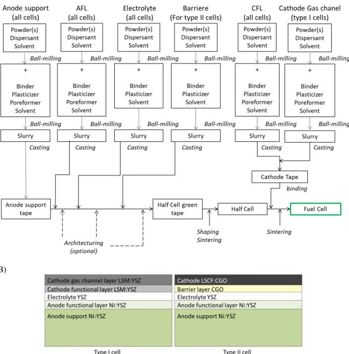
As mentioned, in this study we fabricated two types of cells differentiated by their cathode composition. For type I cells, an LSM:YSZ composite is used, and for type II cells, a LSCF:CGO composite is applied.
III.
Bibliographic survey on performance enhancement for SOFCs
Several paths of SOFC, amelioration are studied in ordered to contribute to SOFC attractiveness: 1) lifespan, 2) pollution resistance, 3) catalytic activity, 4) thermal, mechanical, chemical compatibility and stability, and 5) electrochemical performances. Numerous pathways are currently investigated by the research community starting on a single cell level (new materials, microstructure, geometry, or design) way up to complex hybrid systems involving the synergy of numerous technologies [10] [11] [12] [13].
39 In this chapter, some single solid oxide fuel enhancement techniques are reviewed. They are coarsely categorized in terms of the scale of modification from the conventional design. Many of the modifications can be considered as multiscale, but for the sake of simplicity, only three sections are considered here. In the first part, nanoscale alterations are considered such as alternative materials and/or TPB concentration increase. The two electrode and electrolytes are considered separately, although usually, the use of alternative materials concern the entire cell (ex: use of CGO as intermediate temperature electrolyte, CGO:Ni cermets and CGO:LSCF composites). The second part of this subchapter will concern microscale modification. Here some electrochemical enhancement techniques such as infiltration, exsolution, and impregnation are mentioned as well as the impact on performances of microstructure variations (ex: pore and grain size). The last part will focus on “macroscale” engineering such as electrode-electrolyte interface architecting, layer optimization, and pore structure as well as cell design.
III.A. Materials and microstructure
Adapting the material composition of the elements of the cell is crucial to assure first-rate performances including power density, lifespan, fuel flexibility, and in some cases functioning reversibility. As mentioned previously, the most commonly used materials are Ni:YSZ cermets for the anode, YSZ or CGO for the electrolyte, and perovskite mixed conductors or composites for the cathode such as LSM or LSM:CGO. Although those materials have been proven to have good electrochemical and catalytic performances, they are potential subjects to composition alteration, poisoning, mechanical or microstructural degradation. Ni:YSZ cermets have several well-known deteriorations processes such as sulfur poisoning, carbon coking, Ni grain growth at sintering, and redox cycling [14]. YSZ has excellent chemical, mechanical and thermal stability, and a good pure ionic conductivity at high temperature (> 700°C) [15],[16]. The exponential decrease of this conductivity with the temperature requires either a high-temperature functioning or the use of thin electrolyte layers (~10 µm). One of the YSZ compatible cathode materials is LSM which exhibits a good mixed conductivity and chemical stability, but a low catalytic activity towards oxygen reduction reaction (ORR).
III.A.1. Electrolyte
The ohmic losses in the fuel cell voltage are mainly caused by the electrolyte resistivity. Thus, to increase the electrochemical performance of a single fuel cell, the resistivity needs to be lowered.
40 An enhancement of the global efficiency of the cell can also be considered, by lowering the operating temperature. Two pathways can be explored: 1) increasing the conductivity by either increasing the operating temperature or by using more performant materials, or 2) decrease the thickness of the electrolyte layer thus reducing the transport distance of the ions.
In the late 80s, Steele [17] has presented a practical comparison method of ion-conducting materials by specific conductivity as a function of reciprocal temperature. This method consists of fixing a target-specific resistivity and determine the maximum electrolyte layer thickness to meet this resistivity (figure I – 10). This study has been a guide towards electrolyte development for the last 30 years, promoting material and design innovations.
Figure I - 10 Oxygen transport conduction of oxide materials Steele et al. [17]
III.A.1.a) Materials
Based on figure I – 10, numerous studies on oxides with high ionic conductivity have been carried out, revealing some potential alternatives to YSZ. Sc-doped zirconia exhibits a higher ion conductivity than YZS, but the cost and aging of the material present drawbacks to its use for SOFC technology
41 Bismuth-based electrolyte materials have the highest ion conductivity but their decomposition above 800°C and in reducing atmosphere is problematic for the fabrication and the functioning of HT-SOFC. Doped lanthanum gallium perovskite materials (LGSM) have been considered as an alternative material for LT-SOFC. Despite their good ionic conductivity (0.14 Ω-1.cm-1 at 800°C),
chemical instability, and incompatibility with perovskite or metallic electrodes as well as poor sinterability restrain their use. However, some advances in its stabilization have been reported and its use as electrolyte-supported cells remains interesting [18]. LGSM has been used in a Ni:LDC anode supported cell as an electrolyte film by Bozza et al. [19], exhibiting good electrochemical performances (maximum power density of 0.79 W.cm-2 at 700°C).
The most popular electrolyte alternative for intermediate and low-temperature SOFC are doped ceria based materials. Gadolinium-doped ceria (CGO or GDC) has usually a higher ion conductivity than YSZ at intermediate temperature (σ (Ce0,9Gd0,1O1,95) = 0.025 Ω-1.cm-1
compared to σ (YSZ) =0.005 Ω-1.cm-1 at 600°C), thus being an excellent candidate. Its main
drawback is a reduction of Ce4+ to Ce3+ in reducing atmosphere, causing electronic conductivity and lattice expansion potentially resulting in microcracks. A detailed description of the reducing process is reviewed by Mogensen et al. [6], providing also practical application information for SOFC devices. They review some studies of compatibility between CGO and other SOFC materials such as the works of Tompsett et al. [20] and Sammes et al. [21] which reveal a chemical reaction between CGO or CeO2 and YSZ at prolonged high-temperature thermal
treatment. An insulating cubic phase is formed in YSZ:CGO composites which might hinder the electrochemical properties of the material. Nevertheless, the phase creation is observed after treatment of 72h at 1300°C which is by far longer than any sintering duration of those materials. Furthermore, CGO presents good chemical stability in an oxidizing atmosphere and compatibility with cathode materials such as LSCF (cf. Chap 1 - I.B.3). Thus, one may consider a bilayered CGO/YSZ electrolyte as is the case of Brahim et al. [22] where the researchers studied the electrochemical performances of a thin bilayered electrolyte elaborated by a sputtering technique. A thin CGO barrier layer between the YSZ electrolyte and LSCF based cathode is very commonly used by cell manufacturers such as Forschungszentrum Jülich [23], Fiaxell SOFC Technologies [24], SOFCMAN [25], and many others to promote durability, cathode adhesion, and electrochemical performances.
42
III.A.1.b) Microstructure
Studies of bi-layered electrolytes to improve IT-SOFC performances are reviewed by Shri Prakash et al. [26], considering several material couples other than CGO/YSZ. Extremely high performances bilayer electrolytes with erbium stabilized bismuth oxide (ESB) have been reported by several teams. Joh et al. [27] obtained a maximum power density of 2.1 W.cm-2 at 700°C and 1.6 W.cm-2 at 650°C with ESB/YSZ bilayers and Wachsman et al. [28] as well as Ahn et al. [29] demonstrate a maximum power density close to 2 W.cm-2 at 650°C using ESB/CGO bilayers. A maximum power density of 3.27 W.cm-2 was registered by Ishihara et al. [30] with a modified Ni(Fe) alloy-SDC anode and an LGSM/SDC bilayer electrolyte. The strategy of using a bilayer electrolyte shows a lot of encouraging results and, as mentioned, it is vastly used in the industry (especially CGO/YSZ).
Electrolyte thickness and design are predominant factors for SOFC performances enhancement. The oxygen ion transportation is an energy activated process which is principally responsible for the polarization overpotential of a cell. Thus the correlation between the layer quality (microstructure, thickness, interfaces) and the electrochemical performances needs to be to evaluate its influence on the effect of the architecturation.
III.A.1.c) In this work
Based on the literature review, two types of electrolytes are used. - Simple 8YSZ layer type I cells
- 8YSZ electrolyte layer followed by a CGO10 barrier layer
III.A.2. Anode
Electrode optimization is crucial for overall SOFC efficiency amelioration. This may be achieved by: 1) enhancing the durability of the anode which is prompt to microstructural or chemical degradation, thus lowering increasing the global rentability of the cell, 2) enhancing the catalytic properties by which the electrochemical performances can be increased and eventually the operating temperature may be decreased. The utilization of composite materials is already an optimization of the electrodes by transforming the reactional zone from a 2D surface at the electrolyte/electrode interface to a 3D volume called Anode Functional Layer (AFL). Thus, a decrease in the activation can be achieved by offering a superior number of active sites.
43 To improve SOFC lifespan and fuel flexibility, anode degradation by carbon deposition (coking) or other poisonings (sulfur) as well as microstructural alterations caused by the reducing atmosphere or the high operating and sintering temperature, alternative anode materials are widely studied. Their use to replace the conventional Ni-YSZ cermet can cope with some of the issues enhancing the overall SOFC performances. Additionally, fabrication technics such as infiltration, exsolution, and impregnation are developed to enhance the electrochemical performances by modifying the nano or microstructure of the electrode.
III.A.2.a) Materials
One of the strategies is to use poison-resisting mixed ion electron-conducting oxides (MIEC) anodes which have also the advantage to present extended TPB, passing from 1D TPB to a 2D surface TPB which increases drastically number of reactional sites. Some researchers used doped titanate perovskites, due to their stability in redox conditions and their good electronic conductivity. Strontium titanate (SrTiO3) is one of the most popular examples which is frequently
doped with elements such as La, Cr, Fe, Mn, Cu, Sc, etc in order to increase its conductivity (from 10-5 – 10-1 Ω-1.cm-1 to 1 – 103 Ω-1.cm-1). Flores et al. [31] review the latest advances in this
field and provide an exhaustive list of titanates along with their electrical conductivity and temperature of application. Some lanthanum-doped strontium titanates (LaxSr1-xTiO3) stand out
with high electric conductivity (100 S.cm-1 at 1200 °C and 600 S.cm-1 at 600 °C). Ma and Tietz [32] present a comparison between La and Y doping for SrTiO3 (LST and YST respectively) in
which their conductivity and their thermal and chemical compatibility with YSZ are tested. LST exhibits better conductivity, whereas YST has better chemical compatibility with YSZ and both of the materials are suitable candidates for alternative anode material. YST-YSZ composites have also been studied and characterized by He et al. and by Marina et al [33], showing that LST has adequate thermal, electric and electrocatalytic properties for SOFC electrode use. Miller and Irvine [34] focused on doping the B site of LST by various compounds (La0.33Sr0.67Ti0.92X0.08O3+δ
where X = Al3+, Ga3+, Fen+, Mg2+, Mnn+, and Sc3+) altering the electrocatalytic activity as well as
the conductivity. Numerous related studies have been conducted supporting the potential benefit of titanates usage [35], [36], [37], [38], [39], [40]. Although the titanate perovskites show good chemical stability towards anode degradations, they are yet to achieve the electrochemical performances of Ni:YSZ cermets.
44 Other materials have been considered as Ni:YSZ substitutes such as Cu:CeO2 cermets as well as
Cu with Sm-doped ceria [41]. In their work, Costa-Nunes and al. [42] demonstrated excellent performances of Cu-CeO2 or Cu–Co–CeO2–YSZ anodes for H2, CO, and syngas. Ceria-based
anodes with Cu exhibited very high resistance to sulfur poisoning as shown by He, Gorte et Vohs [43] who did not observe any degradation when introducing up to 450 ppm of H2S. Huang and
Goodenough studied the electronic conductivity and anode performance in H2, H2 containing 5%
H2S and CH4 of the double perovskite Sr2MgMnO6-δ. They demonstrated good electrochemical
performances and stability (over Pmax=0,8 W.cm-² in H2 and H2/H2S and Pmax=0,44 W.cm-² in
CH4) [44], [45].
Although some alternative materials offer good resistance to poisoning, they rarely can match Ni catalytic activity towards H2 and its excellent conductivity. Thus, to maintain electrochemical
performances, the transition metal remains an important element for SOFC functioning. Some authors put forward the use of rare earth doped ceria as a substitute for YSZ in Ni-based cermets especially for low-temperature SOFC due to its good ionic conductivity. For example, nickel and gadolinium doped ceria cermets (Ni:CGO) have exhibited coke resistance with CH4 on several
occasions [46], [47] and potential use to increase triple-phase boundary concentration by infiltration or impregnation.
III.A.2.b) Microstructure
A multitude of papers has been published on electrode microstructure optimization based on either experimental data, analytical calculations, or numerical simulations demonstrating a considerable influence on SOFC performances. The dominating parameters are usually equivalent to the anode and the cathode such as porosity, pore size, grain size, TPB concentration, and accessibility.
Porosity optimization
Jo et al. [48] conduct a study on the physical parameters of a single cell using an electrochemical model. They determine that in a non-graded electrode, the optimum porosity is 42 %vol and the optimum pore radius is 2.4 μm. In the case of a graded electrode, the optimum porosity and pore size are 30 % and 2.2 μm respectively. In their work, the authors demonstrate that grading the porosity of the anode has a consequent effect on the maximum power density, achieving