Science Arts & Métiers (SAM)
is an open access repository that collects the work of Arts et Métiers Institute of Technology researchers and makes it freely available over the web where possible.
This is an author-deposited version published in: https://sam.ensam.eu
Handle ID: .http://hdl.handle.net/10985/8864
To cite this version :
Sofiane DJEBARRI, JeanFrederic CHARPENTIER, Franck SCUILLER, Mohamed BENBOUZID -A Systemic Design Methodology of PM Generators for Fixed-Pitch Marine Current Turbines - In: Green Energy, 2014 International Conference on, Tunisia, 2014-03 - Green Energy, 2014 International Conference on - 2014
Any correspondence concerning this service should be sent to the repository Administrator : [email protected]
978-1-4799-3602-1/14/.00 ©2014 IEEE
A Systemic Design Methodology of PM Generators
for Fixed-Pitch Marine Current Turbines
Sofiane Djebarri1,2, Jean Frédéric Charpentier1, Franck Scuiller1
1
French Naval Academy, EA 3634 IRENav, Brest, France Email: [email protected] Mohamed Benbouzid2 2 University of Brest, EA 4325 LBMS, Brest, France Email: [email protected]
Abstract—This paper deals with the systemic design of
permanent magnet (PM) generator associated with fixed-pitch turbine for tidal energy generation. The main problem with marine current turbines systems are the maintenance requirements of the drive-train. It is known that the blade pitch system increases the complexity, cost, and the maintenance requirements of the drive-train. In offshore energy generation, the maintenance should be minimized as much as possible. For that purpose direct-drive permanent-magnet machines associated with fixed-pitch marine turbines can be an attractive solution. The main challenge with fixed-pitch blades is to ensure the power limitation of the turbine at high speed without using variable pitch system. As solution, we propose a systemic design approach of the generator that takes into account the power limitation requirement. In addition, this methodology takes into account the tidal site energy potential, the turbine characteristic, the control strategy, the generator specifications and the power converter constraints. The obtained results show the feasibility of our approach to satisfy the control strategy requirements.
Keywords—Marine current turbine, fixed-pitch turbine, direct-drive, permanent magnet generator, systemic design.
I. INTRODUCTION
Tidal energy is a renewable source of energy; its potential is easily predictable many years in advance. This energy is generated by the ocean current that results from the contribution of the gravitational forces of the moon and the sun on the oceans (tides) [1]. The total potential of this energy resource is estimated to 450TWh/year, with about 24TWh/year on the European coasts. This resource is distributed mainly among UK with 48 %, France 42% and Ireland 8% of the European potential [2]. Therefore, it constitutes a good alternative to complete the other renewable energy resources for power generation. In addition, the predictable nature of this energy resource is highly interesting for electrical grid connection of marine current turbines. This aspect facilitates the management of the produced electricity. Other advantages can make this energy resource interesting to be exploited, such as reduced environmental impact, low visual pollution and noise exposure for the population [3].
This work is funded by the French Navy and is supported by ECA-EN Company.
Marine current turbines (MCTs) are submerged under seawater and intended to produce energy from tidal currents [1]. The MCTs systems can be similar in principle to the drive-train systems used in wind turbines generation, it can include the following elements: 1) The turbine: According to [4], horizontal axis turbines where mainly used for the first industrial MCT prototypes. It can include variable or fixed-pitch blades. The blades orientation mechanism allows the control of the turbine power by varying the blades pitch angle. However, this mechanical control system increases the complexity of the tidal generation system and increases the MCTs failure probability. It should be noted that for an offshore application and particularly for tidal power generation, enhancing reliability and reducing maintenance are key futures for sustainable and cost-attractive exploitation of marine currents [3]. 2) The gearbox: it can be used to increase the drive speed of the generator. Nonetheless, this element causes a major part of failures and maintenance needs. In the case of a direct-drive system, the generator is directly driven by the turbine without using gearbox. 3) The generator: it is an important element in the drive-train as it realizes the energy conversion from mechanical to electrical energy. In direct-drive direct-drive-train, low speed permanent-magnet (PM) machines are mainly used. In this case, the rotational generator speed is typically below 50 rpm for high power turbines (MCTs). 4) The power converter: it allows the control of the generator and the power regulation before its injection into the electrical grid. Several architectures of power converters are possible for MCTs [5]. A Back-to-back double-bridge IGBT converter is considered in this work. 6) The storage system: it can be used in particular configurations for smoothing the electrical power before being injected into the electrical grid [6].
Referring to [7], the gearbox and the blades variable pitch systems are the main sources of failure and maintenance in wind turbine applications. With tidal power generation the maintenance is a key future because it is really difficult to ensure maintenance operations on immersed seawater MCTs. In addition the maintenance adds significant additional costs. In order to reduce maintenance requirements, a simple architecture of the drive-train is proposed in this study (Fig. 1). A direct-drive PM generator is considered for a fixed-pitch blade turbine.
Power limitation strategy is interesting to a cost-attractive sizing of electrical energy conversion chain.
Fig. 1. Marine current turbine drive-train, with direct-drive generator and fixed-pitch blades.
It avoids a significant oversizing of the electrical elements. When the turbine has variable-pitch blades, the power limitation strategy is achieved mechanically by varying the blades pitch angle. For fixed-pitch turbines, the power limitation control can be electrically carried out by torque and speed control of the generator considering over speed flux-weakening operations [8]. In this paper, we propose a specific design methodology of a Radial Flux Permanent Magnet (RFPM) generator to perform power limitation control strategy only through the RFPM generator control. For that purpose, a systemic design approach of the PM generator is proposed. It takes into account the control strategy, the generator specifications, the energy resource characteristic, the turbine power coefficient (Cp) law and the converter voltage and current constraints. This systemic design methodology is described in the second part of the paper. In the third part, a design is achieved according to the given methodology and the results are discussed.
II. DESIGN METHODOLOGY A. Tidal Resource Modeling and Analysis
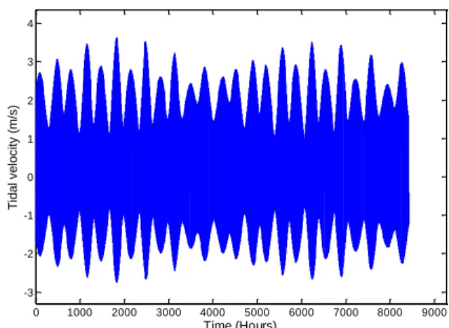
In this study, Raz de Sein tidal site, France, is considered thanks to its high tidal current velocity and favorable location near the coasts. The GPS coordinates of the studied site are (φB = 48°02’42’’, GB=4°45’45’’). The used data consist of the velocity values for each hour during a tidal period of 8424hours [1]. The tidal velocity is here varying between -2.75m/s to 3.63m/s. Figure 2 show the velocity variation during the considered period.
If the tidal speed range is divided by n interval and the speed in the ith interval is vi, Fig. 3 represents the occurrences OCCi (number of hours) corresponding to the ith tidal speed interval in the considered tidal period. OCCi corresponds to the number of hours in the ith tidal interval around the speed vi. Knowing the occurrence of the tidal velocity, it is possible to calculate the corresponding energy potential density (Wh/m2) by the following formula.
1 3
2 i p i water i i i E OCC Where Eipis the energy potential given in (Wh/m
2), ρ
water is
the water density, vi is the tidal speed ,and OCCi is the occurrences at speed vi. 0 1000 2000 3000 4000 5000 6000 7000 8000 9000 -3 -2 -1 0 1 2 3 4 Time (Hours) T id a l ve lo ci ty (m /s)
Fig. 2. Tidal velocity in Raz de Sein site, France.
-3 -2 -1 0 1 2 3 4 200 400 600 800 1000 1200 Tidal speed (m/s) O ccu rr e n ce s (H o u rs)
Fig. 3. Occurrences (OCCi) versus tidal velocity (vi).
Figure 4 illustrates the energy density potential distribution deduced from (1). It can observe that the energy potential distribution at Raz de Sein tidal site follows a Gaussian law distribution. This law is constituted by two normal laws, one for the positive values of tidal speed and the other one for the negative values. This analytical interpolation law can be modeled by -3 -2 -1 0 1 2 3 4 0.5 1 1.5 2 2.5 3 3.5
Marine current velocity (m/s)
E n e rg y d e n si ty (M W h /m 2 )
Energy potential distribution
Analytical law of energy potential distribution
2 1.8622 0.6888 2.426 0.8915 1 57.09 31.068 i i i p i E e e n Where n is the sample number of tidal velocity.
If the energy potential of the tidal site is known for each speed value, it is possible to calculate the turbine extractable energy by
i i i p i turbine p i E E S C Where 2 4 turbine turbineS D is the turbine blade swept area and
Cp ((vi)) is the power coefficient given for a Tip-Speed-Ratio (TSR) (vi) which is determined for each speed value vi. B. Turbine Modeling
The turbine is characterized by the Cp (power coefficient) law. For a fixed-pitch turbine this factor is given as a function of . The TSR is defined as the ratio between the blades peripheral speed to the tidal current speed.
2
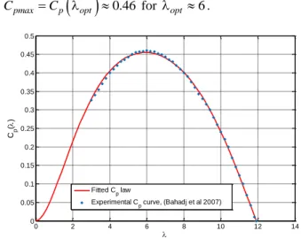
turbine D Where Ω (rad/s) is the generator rotational speed, Dturbine (m) is the turbine diameter and v (m/s) is the tidal current speed. In this study, Cp data of an experimental underwater turbine prototype is used [9]. These experimental data are fitted by an analytical law as
0.3958 1.539 2 0.0195 1.3172 0.0867 cos 0.4019 5.6931 0 11.8 p C e As shown in Fig. 5, the Cp curve calculated with the proposed analytical law matches the experimental one given in [9].
We assume in this work that the considered turbine has a diameter of 12m and it operates at a tidal speed of 1m/s. It has a CpmaxCp
opt 0.46 for opt 6.0 2 4 6 8 10 12 14 0 0.05 0.1 0.15 0.2 0.25 0.3 0.35 0.4 0.45 0.5 Cp ( ) Fitted C p law
Experimental Cp curve, (Bahadj et al 2007)
Fig. 5. Cp law of the considered turbine.
C. Control Strategy Description
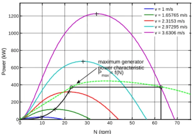
In this section, we define the turbine control strategy from the tidal speed characteristic and the turbine specifications. For a given value of and v the turbine extracted power is calculated by (Fig. 6)
2 3
8
turbine water turbine p
P D C In Fig. 4, it can be seen that the tidal current energy potential is very low at high tidal speed. It is then obvious that the limitation power strategy is interesting to avoid a power oversizing of the electrical conversion chain. Figure 6, particularly illustrates P* that denotes the turbine reference operating power (control strategy). It is calculated by
2 3
if 8
if
water turbine pmax Lim
Lim Lim D C P P
PLim is the limitation value of the turbine power. If PLim is known, it is obviously possible to determine the limit tidal speed vLim where the limitation power strategy is applied. It is calculated by
3 2
8
Lim Lim
water turbine pmax
P D C
The base rotation speed Ωb (rad/s) of the generator is then deduced as below
2
opt Lim b turbine D Then the base rotational speed in rpm is: 60
2
b b
N
The maximal speed (given at the limit operating point of Fig. 6) is defined by 0 10 20 30 40 50 60 70 0 200 400 600 800 1000 1200 N (rpm) P o w e r (kW ) v = 1 m/s v = 1.65765 m/s v = 2.3153 m/s v = 2.97295 m/s v = 3.6306 m/s base point (N b, PLim) Control strategy limit point (N Lim, PLim) MPPT power limitation to P Lim
2
Lim Lim Lim turbine D and 60 2 Lim Lim N Where Lim is calculated by solving the following equation.
Limp
2 3
water turbine max P C 0 D 8
Equation (14) gives the extracted energy by the turbine considering the chosen tidal site and adopting the described limitation power strategy.
1 n extracted i i i i E P OCC
Figure 7 gives the extracted energy when the limitation power rate is varying. PLim is varying from 5% to 100% of the maximum power that can be extracted by the considered turbine (Pmax = P(Cpmax,vmax) = 1245kW in the studied case). It clearly shows that limiting the power at high tidal speed to 30% of the maximum turbine power is enough to extract 87.5% of the total extractible energy. Then the limitation power is set to PLim = 374kW. According to this control strategy the turbine operates until 7864hours with MPPT control and 560hours in power limitation mode. Therefore 75% (656MWh) from the total extracted energy (884MWh) is extracted during the MPPT control mode and 25% (228MWh) during the limitation power mode.
The torque setpoint characteristic that the generator-drive should develop during an operating rotational speed cycle is deduced from
2 60
P N 10 20 30 40 50 60 70 80 90 100 110 30 40 50 60 70 80 90 100 Power Limitation % E xt ra ct e d E n e rg y % E % = 87.5 % P Lim = 30%Fig. 7. Extracted energy rate versus power limitation rate.
Figure 8 gives the torque characteristic that the generator should be able to develop. This characteristic is then introduced as a specification to design the PM generator. It can be observed from this figure that the design torque characteristic can be introduced as two design points. The first one is the base point where the machine must develop the base torque Γb (it corresponds to the maximum torque) at base speed Nb. The second one is an over speed limit point, this point is introduced as a constraints in the generator design specifications. It traduces the torque ΓLim that the generator should be able to produce at the maximum rotational speed NLim of the turbine during an operating cycle.
D. Power Converter Limits
In our methodology the power converter constraints are taken into account. The converter is considered as a double bridge IGBT back-to-back one [5]. The grid side converter voltage is set to Vgrid = 690V (rms). This voltage corresponds to a typical output voltage of offshore wind turbines [10]. Then the maximum generator phase voltage allowed by the power converter is here set to Vmax = Vgrid. Vmax corresponds to the power converter input voltage.
E. Generator Calculation
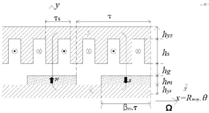
1) Generator modeling. The generator is a radial flux permanent magnet machine and it is modeled considering the geometry illustrated in Fig. 9. The used models consist mainly on electromagnetic model coupled with a thermal one as described in [11-12]. These models allow calculating the electromagnetic torque, the electrical power, the electrical losses and the thermal behavior over the speed range operating cycle.
2) Optimization problem formulation. The generator design is formulated as an optimization problem that consists on minimizing the active parts costs function C(x) under linear and nonlinear constraints. This mono-objective function takes into account the magnets, copper, and iron sheets costs. x is here the geometry variables. The constraints consist of:
Equality constraint on the generator torque at the base speed Γb(x,Ωb). 0 10 20 30 40 50 60 0 20 40 60 80 100 120 140 160 N (rpm) T o rq u e ( kN m ) Limit point (N Lim,Lim) Base point (N b,b)
Fig. 9. Geometry of the RFPM generator: hyr is the rotor yoke height, hm is the magnet height, hg is the air gap height, hs is the slot height, hys is the stator yoke height, βm is the magnet-to-pole width ratio, τs is the slot pitch width, βt is the tooth-to-slot width ratio.
Equality constraint on the generator phase voltage V(x,ΩLim). This constraint is introduced by the power converter input voltage.
Inequality constraint on the generator torque at the limit operating speed. Thereby the generator torque ΓLim(x,ΩLim) at maximum speed ΩLim must be higher than the required torque at this speed.
Inequality constraint on the power factor FP. The power factor FP(x,Ωb) at base speed must be higher than a fixed minimal power factor value FPmin This constraint is introduced to avoid a very low power factor at low speed.
Inequality constraint on the electrical efficiency. The generator electrical efficiency ηelec(x,Ωb) must be higher than a minimal set value ηelec,min. This constraint is defined to avoid very low generator electrical efficiency.
Inequality constraint on the maximum generator temperature. This constraint ensures the thermal feasibility of the generator. It is defined as the maximum temperature T(x,Ωb) in conductors at base speed. The temperature T(x,Ωb) should be lower than the maximum temperature Tmax allowed by the conductors class thermal insulation.
Inequality constraint on the maximum magnetic field Hmax(x) in the magnets. The magnetic field in magnets is calculated by considering the worst case where the field created by stator currents is in phase with the magnets field. Therefore to avoid the magnets demagnetization, the value of magnetic field should be lower than the magnets coercive field Hcj.
Linear inequality constraints on the generator geometry variables. They are introduced in the optimization problem to ensure the a PM generator feasible geometry.
Then the optimization problem is summarized (16). III. DESIGN RESULTS AND ANALYSIS A. Electromagnetic Design and Analysis
The optimization process illustrated by (16) is performed under the Matlab optimization toolbox with the fmincon algorithm. To achieve this optimization a set of constraint parameters used in this study are given in Table I. According to the described methodology the generator is designed and the obtained generator geometry parameters are given in Table II.
min * Lim min , 0 , 0 , 0 ( , ) 0 ( , ) 0 ( , ) 0 ( , ) 0 b b b max Lim b min b max max b cj elec b elec C V V PF PF T T H H LB UB x X x x x x x x x x x x Table III gives the electrical parameters and the main performances of the designed generator according to the developed methodology. The generator geometry is illustrated by Fig. 10.
B. Generator Ability in a Speed Cycle Range
Figures 11 and 12 show that the torque/speed and power/speed characteristics of the generator are over the specified torque/speed and power/speed characteristics (same curves as in Fig. 6 and 8).
TABLE I. GENERATOR SPECIFICATIONS.
Generator external diameter Dgenerator 3 m
Turbine torque at base speed Γb 155.6 kNm
Turbine base speed Nb 22.35 rpm
Turbine torque at maximum speed ΓLim 57 kNm
Turbine limit speed NLim 62.7 rpm
Tidal speed at base point vLim 2.5 m/s
Power converter input voltage Vmax 690 V(rms)
Generator power factor at base speed PF 0.82 -
Minimal generator electrical
efficiency ηelecmin 0.95 -
Maximum generator temperature Tmax 100 °C
Magnets coercive field Hcj 106 A/m
TABLE II. DESIGNED GENERATOR.
J Current density 3.38 A/mm2
AL Electrical load 52735 A/m
B1 First harmonic of the Air gap flux density 0.89 T
p Pair pole number 39 -
ncd Number of conductors in series per slot per
phase 9 -
m Phase number 3 -
Spp Slot number per pole per phase 1 -
kf Slot fill factor 0.5 -
kb1 Winding coefficient given at first harmonic 1 -
Ri Inner radius 1.32 m
Re Outer radius 1.486 m
Rs Stator bore radius 1.362 m
Lm Active length 40.3 cm
βm Magnet to pole width ratio 66 %
βt Teeth pitch ratio 68.5 %
hys Stator yoke thickness 2.5 cm
hyr Rotor yoke thickness 2.5 cm
hs Slot height 10 cm
hm Magnet height 1.15 cm
TABLE III. GENERATOR CHARACTERISTICS.
E1 Phase electromotive force (emf) 582 V (rms)
V Phase voltage 690 V (rms)
Xs Synchronous reactance 1.9
rs Phase resistance 0.107
Cosφ Power factor at base speed 0.82 -
ηelec Generator efficiency 95.3 %
Tcoils Maximum temperature in coils 54 °C
Hmax Maximum magnetic field in magnets 0.47 MA/m
Pj Joule losses at base speed 15.4 kW
Pfer Iron losses at base speed 2.04 kW
D = 2.972 m , Lm = 40.3 cm
(b) (b)
Fig. 10. View of the generator active parts section (a), Zoom on the generator active parts (b). 0 10 20 30 40 50 60 0 20 40 60 80 100 120 140 160 N (tr/min) T o rq u e ( kN m )
Specified Torque/Speed characteristic Generator Torque/Speed characteristic
Base point (Nb,b)
Limit point (NLim,Lim)
Fig. 11. Required torque/speed specification and generator torque/speed characteristic. 0 10 20 30 40 50 60 70 0 200 400 600 800 1000 1200 N (rpm) P o w e r (kW ) v = 1 m/s v = 1.65765 m/s v = 2.3153 m/s v = 2.97295 m/s v = 3.6306 m/s maximum generator power characteristic Pmax = f(N)
Fig. 12. Power control strategy and developable generator power.
This result implies that the electrical power limitation strategy at high tidal speed can be performed only by controlling the designed generator according to the developed methodology.
IV. CONCLUSION
In this paper a systemic design methodology of direct-drive permanent magnet generator associated with a fixed-pitch turbine for tidal generation has been proposed. The used control strategy is based on the power limitation at high tidal currents speed without blade pitching. This strategy is only based on the generator control adopting a flux weakening approach. The developed design methodology takes into account the main elements of the conversion chain as the resource characteristic, the turbine law, the generator specifications, the control strategy and the converter constraints. It allows determining the torque/speed characteristic as a design specification of the generator. The obtained results show that the designed generator fulfills the required torque characteristic over the speed range that confirms the relevance of our methodology. Therefore the limitation power at high tidal speed can be achieved without using variable pitch system.
REFERENCES
[1] S. Benelghali, R. Balme, K. Le Saux, M.E.H. Benbouzid, J.F. Charpentier and F. Hauville, “A simulation model for the evaluation of the electrical power potential harnessed by a marine current turbine,” IEEE Journal on
Oceanic Engineering, vol. 32, n°4, pp. 786-797, October 2007.
[2] Technical Report, Groupe 12A, Les Hydroliennes, Projet ADEM1 (in French): http://www.heliciel.com/Library/Rapport%20hydrolienne.pdf, 2005.
[3] M. Leijon, H. Bernhoff, M. Berg and O. Ågren, “Economical considerations of renewable electric energy production—especially development of wave energy,” Renewable Energy, vol. 28, n°8, p. 1201-1209, 2003.
[4] S. Djebarri, J.F. Charpentier, F. Scuiller and M.E.H. Benbouzid, “Génératrice à aimants permanents à flux axial à grand diamètre avec entrefer immerge – Eléments de conception et analyse des performances pour un cahier des charges d’hydrolienne,” European Journal of Electrical
Engineering, vol. 16, n°2, pp. 145-176, 2013.
[5] J.A. Baroudi, V. Dinavahi and A.M. Knight, “A review of power converter topologies for wind generators,” Renewable Energy, vol. 32, n°14, p. 2369-2385, 2007.
[6] Z. Zhou, M.E.H. Benbouzid, J.F. Charpentier, F. Scuiller and T. Tang, “A review of energy storage technologies for marine current energy systems,”
Renewable & Sustainable Energy Reviews, vol. 18, pp. 390-400, February
2013.
[7] Y. Amirat, M.E.H. Benbouzid, E. Al-Ahmar, B. Bensaker and S. Turri, “A brief status on condition monitoring and fault diagnosis in wind energy conversion systems,” Renewable & Sustainable Energy Reviews, vol. 3, n°9, pp. 2629-2636, December 2009.
[8] Z. Zhou, F. Scuiller, J.F. Charpentier, M.E.H. Benbouzid and T. Tang, “Power limitation control for a PMSG-based marine current turbine at high tidal speed and strong sea state,” in Proceedings of the 2013 IEEE IEMDC, Chicago (USA), pp. 75-80, May 2013.
[9] A.S. Bahaj, A.F. Molland, J.R. Chaplin and W.M. J. Batten, “Power and thrust measurements of marine current turbines under various hydrodynamic flow conditions in a cavitation tunnel and a towing tank,”
Renewable Energy,, vol. 32, n°3, p. 407-426, 2007.
[10] Siemens SWT-6.0-154 6MW, Technical Report. available at http://www.swe.siemens.com/spain/web/es/energy/energias_renovables/eol ica/Documents/6MW_direct_drive_offshore_wind_turbine.pdf (last acceced: December 2013).
[11] S. Djebarri, J.F. Charpentier, F. Scuiller, M.E.H. Benbouzid and S. Guemard, “Rough design of a double-stator axial flux permanent magnet generator for a rim-driven marine current turbine,” in Proceedings of the
2012 IEEE ISIE, Hangzhou (China), pp. 1450-1455, May 2012.
[12] L. Drouen, J. F. Charpentier, E. Semail and S. Clenet, “Study of an innovative electrical machine fitted to marine current turbines,” in
Proceedings of the 2007 IEEE OCEANS, Aberdeen (Scotland), pp. 1-6,