Science Arts & Métiers (SAM)
is an open access repository that collects the work of Arts et Métiers Institute of
Technology researchers and makes it freely available over the web where possible.
This is an author-deposited version published in: https://sam.ensam.eu
Handle ID: .http://hdl.handle.net/10985/10027
To cite this version :
Germanico GONZALEZ-BADILLO, Hugo MEDELLIN-CASTILLO, Theodore LIM, James M.
RITCHIE, Raymond C.W. SUNG, Samir GARBAYA - A new methodology to evaluate the
performance of physics simulation engines in haptic virtual assembly Assembly Automation
-Vol. 34, n°2, p.128-140 - 2014
Any correspondence concerning this service should be sent to the repository
Administrator : [email protected]
Assembly Automation
A new methodology to evaluate the performance of physics simulation engines in haptic virtual assembly
Germanico Gonzalez-Badillo Hugo I. Medellin-Castillo Theodore Lim James M. Ritchie Raymond C.W. Sung Samir Garbaya
Article information:
To cite this document:
Germanico Gonzalez-Badillo Hugo I. Medellin-Castillo Theodore Lim James M. Ritchie Raymond C.W. Sung Samir Garbaya ,
(2014),"A new methodology to evaluate the performance of physics simulation engines in haptic virtual assembly", Assembly
Automation, Vol. 34 Iss 2 pp. 128 - 140
Permanent link to this document:
http://dx.doi.org/10.1108/AA-05-2013-046
Downloaded on: 23 July 2015, At: 00:17 (PT)
References: this document contains references to 49 other documents.
To copy this document: [email protected]
The fulltext of this document has been downloaded 180 times since 2014*
Users who downloaded this article also downloaded:
Germanico Gonzalez-Badillo, Hugo Medellin-Castillo, Theodore Lim, James Ritchie, Samir Garbaya, (2014),"The development
of a physics and constraint-based haptic virtual assembly system", Assembly Automation, Vol. 34 Iss 1 pp. 41-55 http://
dx.doi.org/10.1108/AA-03-2013-023
Hong Xiao, Yuan Li, Jian-Feng Yu, Hui Cheng, (2014),"Dynamic assembly simplification for virtual assembly process of complex
product", Assembly Automation, Vol. 34 Iss 1 pp. 1-15 http://dx.doi.org/10.1108/AA-12-2012-093
Wanbin Pan, Yigang Wang, Peng Du, (2014),"Automatic disassembly navigation for accurate virtual assembly path planning",
Assembly Automation, Vol. 34 Iss 3 pp. 244-254 http://dx.doi.org/10.1108/AA-01-2014-008
Access to this document was granted through an Emerald subscription provided by All users group
For Authors
If you would like to write for this, or any other Emerald publication, then please use our Emerald for Authors service
information about how to choose which publication to write for and submission guidelines are available for all. Please visit
www.emeraldinsight.com/authors for more information.
About Emerald www.emeraldinsight.com
Emerald is a global publisher linking research and practice to the benefit of society. The company manages a portfolio of
more than 290 journals and over 2,350 books and book series volumes, as well as providing an extensive range of online
products and additional customer resources and services.
Emerald is both COUNTER 4 and TRANSFER compliant. The organization is a partner of the Committee on Publication Ethics
(COPE) and also works with Portico and the LOCKSS initiative for digital archive preservation.
*Related content and download information correct at time of download.
A new methodology to evaluate the
performance of physics simulation engines
in haptic virtual assembly
Germanico Gonzalez-Badillo and Hugo I. Medellin-Castillo
Facultad de Ingenierı´a, Universidad Auto´noma de San Luis Potosı´, San Luis Potosı´, Mexico
Theodore Lim, James M. Ritchie and Raymond C.W. Sung
Department of Mechanical Engineering, Heriot-Watt University, Edinburgh, UK, and
Samir Garbaya
Institut Image, Arts et Metiers ParisTech, Chalon sur Saone, France
Abstract
Purpose – In this study, a new methodology to evaluate the performance of physics simulation engines (PSEs) when used in haptic virtual assembly applications is proposed. This methodology can be used to assess the performance of any physics engine. To prove the feasibility of the proposed methodology, two-third party PSEs – Bullet and PhysXtm – were evaluated. The paper aims to discuss these issues.
Design/methodology/approach – Eight assembly tests comprising variable geometric and dynamic complexity were conducted. The strengths and weaknesses of each simulation engine for haptic virtual assembly were identified by measuring different parameters such as task completion time, influence of weight perception and force feedback.
Findings – The proposed tests have led to the development of a standard methodology by which physics engines can be compared and evaluated. The results have shown that when the assembly comprises complex shapes, Bullet has better performance than PhysX. It was also observed that the assembly time is directly affected by the weight of virtual objects.
Research limitations/implications – A more comprehensive study must be carried out in order to evaluate and compare the performance of more PSEs. The influence of collision shape representation algorithms on the performance of haptic assembly must be considered in future analysis. Originality/value – The performance of PSEs in haptic-enabled VR applications had been remained as an unknown issue. The main parameters of physics engines that affect the haptic virtual assembly process have been identified. All the tests performed in this study were carried out with the haptic rendering loop active and the objects manipulated through the haptic device.
Keywords Bullet, Haptics, Virtual assembly, Physics simulation engines, PhysX Paper type Research paper
1. Introduction
Virtual assembly platforms (VAPs) can be used as a tool to interrogate product form, fit and function even before the manufacturing of real prototypes, thereby shortening the design cycle time and improving product manufacturability while reducing assembly cost. Haptics is an evolving technology that enhances the sense of presence, realism and interaction in virtual reality applications through the sense of touch (Jayaram et al., 1997). Haptic devices are capable to render both tactile and kinematic force feedback, simulating the virtual objects’ shape, roughness, stiffness, weight, inertia, etc. Haptic devices are increasingly being chosen as interaction interfaces for VAPs, over conventional glove-based devices or 3D-mice, being the key benefit the kinaesthetic feedback that users receive while performing a virtual assembly.
Howard and Vance (2007) mentioned that a successful virtual assembly environment requires virtual parts to emulate real world parts behaviour. According to Seth et al. (2011) this can be achieved by means of physics-based modelling (PBM), which uses physics simulation engines (PSEs) to simulate real world physics properties, such as friction, gravity and contact forces to perform the assembly. The use of PBM results in better appreciation and understanding of part functionality and can also lead to improved training of manual tasks (Wang et al., 2001; Zerbato et al., 2011). However, there are several challenges when integrating haptics with PSEs, e.g. synchronization, non-effective collision detection, high computational cost and a negative impact on the performance of the application (Seugling and Ro¨ lin, 2006), mainly because simulation engines have not been developed for haptic rendering, where the update frequency is over 1 kHz while the physics simulation update rate is around 100 Hz (Ritchie et al., 2008a, b; Glondu et al., 2010). The aim of this paper is to present a methodology to evaluate the performance of PSEs by identifying their strengths, limitations and weaknesses when used in haptically
The authors acknowledge the financial support from CONACYT (National Science and Technology Council of Mexico) research grant CB-2010-01-154430 and EPSRC/IMRC grants 113946 and 112430.
enabled VAPs. The proposed methodology consists on a set of assembly tests with variable geometric and dynamic complexity. In order to validate this methodology two of the most common PSEs are evaluated, i.e. PhysX v2.8.4 and Bullet v2.81.
2. Related work
2.1 Virtual assembly systems
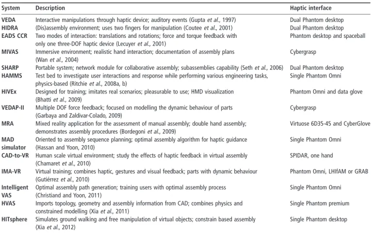
Several authors have developed VAPs using different assembly techniques, such as feature matching recognition (Iacob et al., 2011; Sato et al., 2011), constrained based modelling (Zaldivar-Colado and Garbaya, 2009; Gutie´rrez et al., 2010; Tching et al., 2010), PBM (Gupta et al., 1997; Lim et al., 2007; Garbaya and Zaldivar-Colado, 2009; Chamaret et al., 2010; Aleotti and Caselli, 2011; Xia et al., 2012), import of CAD assembly constraints (Jayaram et al., 1999; Chen et al., 2010; Cheng-jun et al., 2010), and the use of haptics (Ritchie et al., 2008b; Bordegoni et al., 2009; Ladeveze et al., 2010; Liu et al., 2010; Ji et al., 2011; Christiand and Yoon, 2011). Some of these systems are summarized in Table I. Three main applications of virtual assembly systems are identified: assembly planning, maintenance (disassembly) analysis and training. However, the effect of simulation parameters and components, such as the force feedback, PSE, collision shape representation, etc. on the haptic virtual assembly performance has not been clarified. Several systems in literature use PBM to simulate the assembly process and have reported problems regarding the collision response and interpenetration between
virtual parts; for instance Howard and Vance (2007) used triangle meshes for collision detection and reported that whereas mesh-mesh assembly enabled accurate collision detection, realistic physical response was not demonstrated, particularly when objects had continuous contact with each other.
2.2 Physics simulation engines
According to Laurell (2008) five key points are identified in any PSE: contact detection, contact resolution, force calculation, integrating motion and the impact of real time constraints (time step), where anything below 25 frames per second (fps) is perceived as slow and stammering. Moreover, Seth et al. (2011) identified three main challenges that virtual assemblies must overcome to increase the level of realism: collision detection, inter-part constraint detection and PBM.
Seugling and Ro¨lin (2006) compared three physics engines – Newton, ODE and PhysX – with the following run-time executions: friction on a sliding plane; gyroscopic forces; restitution; accuracy against real; stability of piling (pile of boxes); scalability of constraints; and complex contact between primitive, convex and mesh models. In most of the tests PhysX was the best evaluated PSE, except in the stability of piling and the mesh-mesh collision detection tests, where undesired behaviour was observed. Boeing and Bra¨unl (2007) carried out a comparative evaluation between PhysX, Bullet, JigLib, Newton, ODE, Tokamak and True Axis using PAL (Physics Abstraction Layer). Their comparison criteria
Table I Haptic virtual assembly systems reported in the literature
System Description Haptic interface
VEDA Interactive manipulations through haptic device; auditory events (Guptaet al., 1997) Dual Phantom desktop
HIDRA (Dis)assembly environment; uses two fingers for manipulation (Couteeet al., 2001) Dual Phantom desktop
EADS CCR Two modes of interaction: translations and rotations; force and torque feedback with
only one three-DOF haptic device (Lecuyeret al., 2001)
Phantom desktop and spaceball
MIVAS Immersive environment; realistic hand interaction; documentation of assembly plans
(Wanet al., 2004)
Cybergrasp
SHARP Portable system; network module for collaborative assembly; subassemblies capability (Sethet al., 2006) Dual Phantom desktop
HAMMS Test bed to investigate user interactions and response while performing various engineering tasks,
physics-based (Ritchieet al., 2008a, b)
Single Phantom Omni
HIVEx Designed for training; imitates real scenarios; pleasurable to use; HMD visualization
(Bhattiet al., 2009)
Phantom Omni and data glove
VEDAP-II Multiple DOF force feedback; focused on modelling the dynamic behaviour of parts
(Garbaya and Zaldivar-Colado, 2009)
Cybergrasp
MRA Mixed reality application for the assessment of manual assembly; double hand assembly;
demonstrates assembly procedures (Bordegoniet al., 2009)
Virtuose 6D35-45 and CyberGlove MAD
simulator
Oriented to assembly sequence planning; optimal assembly algorithm for haptic guidance (Hassan and Yoon, 2010)
Single Phantom Omni
CAD-to-VR Human scale virtual environment; study the effects of haptic feedback in virtual assembly
(Chamaretet al., 2010)
SPIDAR, one hand
IMA-VR Virtual training; combines haptic, gestures and visual feedback; parts with dynamic behaviour
(Gutie´rrezet al., 2010)
Phantom Omni, LHIfAM or GRAB Intelligent
VAS
Optimal assembly path generation; training users with optimal assembly process (Christiand and Yoon, 2011)
Single Phantom Omni
HVAS Imports topology, geometry and assembly information from CAD; combines physics and
constrained modelling (Xiaet al., 2011)
Single Phantom premium
HITsphere Simulates ground walking and free manipulation of virtual objects; constrain based assembly
(Xiaet al., 2012)
included: integrator performance, material properties, friction, constraint stability, collision detection system and a stacking test. They concluded that PhysX had the best integrator method, whereas Bullet provided the most robust collision system. Moreover, Coumans and Victor (2007) made a comparison analysis of PhysX, Havok, ODE and Bullet. Collision detection and rigid body features were used as the comparison criteria. The results suggested PhysX as the most complete PSE.
The previous comparative evaluations to investigate the performance of PSEs were carried out without considering the integration of haptic rendering. Regarding this, Glondu et al. (2010) introduced the possibilities of implementing a modular haptic display system that relies on physics simulation and haptic rendering. Four physics simulation libraries were evaluated: Havok, PhysX, Bullet and OpenTissue. The performance criterion was based on computation time, stability and accuracy. PhysX showed penetration in some of the tests whilst Havok showed the best average computation time, stability and friction accuracy. Although haptics was considered in this evaluation, the tests were performed without using a haptic device or a haptic rendering loop.
2.3 Contact forces
In order to provide realistic and stable reaction forces, the PSE must provide a continuous contact resolution when manipulating objects. PSEs use numerical integration to move on from a current state Y(t0) to a new state Y(t0þ Dt), where Dt
is the time step size. The collision detection component must check each new state for possible intersection between objects. If no overlapping is detected the system adopts this new state as the current state. Otherwise, the system must compute the time when the first collision occurred and move on to that state. Once all the points of contact are determined, the system must compute the constraint forces that prevent interpenetration (Baraff, 1995).
The result of a collision between two rigid bodies is a discontinuity in the objects velocity, which can be accurately modelled by applying impulsive forces to virtual objects (Baraff, 1995; Ruspini and Khatib, 1997). These impulsive forces can be computed by analytical or penalty based methods (Ruspini and Khatib, 1997). Analytical methods numerically solve for the exact contact forces and impulses required to guarantee that the simulated bodies never inter-penetrate. Penalty based methods compute restoring forces, typically proportional to the amount of penetration, only after the objects have overlapped. According to Baraff (1989), three constraints must be satisfied when a collision occurs:
1 the velocity after the collision is required to be at least – 1 times the relative velocity at the contact point, where 1 is the restitution coefficient;
2 the impulse forces at the contact point can only push but not pull objects; and
3 the contact forces occur only at contact points. 2.4 Haptic perception
Huang et al. (2002) studied the effects of haptic feedback on user performance during a dynamic task. The results showed that high feedback conditions improve user performance. In a similar work, Lim et al. (2007) investigated the impact of haptic rendering on user efficiency in assembly tasks. It was observed that small changes in shape, the use of full collision detection and the use of stereo-view, can affect assembly times in haptic
virtual assembly environments. Similar results were obtained by Garbaya and Zaldivar-Colado (2007), who observed that human operators have better performance when force feedback is provided during assembly tasks.
The previous background studies indicate that several research works have been focused on virtual assembly simulation. However, when PBM is used in haptic virtual assembly, the PSE exhibited certain problems, e.g. unreal collision response and low update rates. Various evaluations have been conducted to assess the performance of different PSEs, but these evaluations have not considered the effect of haptics. The proposed methodology considers the effect of haptic rendering on the performance of PSEs within a physics based virtual assembly environment. The collision detection response is also considered within this methodology. The performance of PSEs is measured in terms of the task completion time (TCT), weight perception and force feedback.
3. System overview
A haptic virtual assembly system, named as HAMS (Gonza´lez-Badillo et al., 2013), Figure 1(a), was used to validate the methodology. HAMS integrates two PSEs, PhysX v2.8.4 and Bullet v2.81. Single and dual haptic interaction is provided via two Phantom Omni haptic devices (Figure 1(b)). HAMS also includes the Gilbreth’s chronocyclegraphs (Ritchie et al., 2008a) which track all user movements and allow the graphical analysis of assembly paths. Virtual models can be imported into HAMS as STL or OBJ format files. When a model is loaded, three representations of it are generated: 1 a graphic representation, used for graphic rendering on
the screen;
2 a haptic representation, used to recognize and manipulate virtual objects using the haptic device; and
3 a physics representation (collision shape) to provide physics-based behaviour and collision detection to virtual object by means of the PSE.
4. Evaluation methodology
The proposed methodology consists of eight tests with variable levels of complexity (Table II ). These tests have been defined to broadly evaluate the performance of PSE in virtual assembly applications. Tests 1-6 evaluate individual properties of each PSE such as collision response and stability under different simulation conditions. Tests 7 and 8 comprise the virtual assembly of complex components representing real parts, the aim is to assess the PSE performance in more general assembly tasks.
4.1 Free-fall test
The objective is to assess the integrator method of each PSE, which is related to the numerical algorithms used to calculate the new position of an object at each time step during the simulation. Its performance is affected by several factors such as the simulation time step, virtual model complexity, scene complexity, the number of objects in the scene, etc. The integrator performance affects the user perception of the simulation; a bad performance may create different effects such as low gravity behaviour (moon effect), the penetration among models, instability of the assembled components, and even the discontinuity of the simulation. An adequate integrator performance will result in a fast, accurate and smooth simulation.
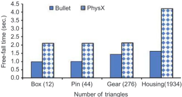
The free-fall test consists on dropping virtual objects from an elevation of 500 units and measuring the time to reach the floor (Figure 2). The free-fall time reflects how fast the integrator method works. A short free-fall time suggest a good performance of the integrator method. Two conditions were evaluated: 1 influence of shape complexity (number of triangles); and 2 influence of haptic loop on the integrator performance. Four virtual models with different complexity were selected to perform this test: a box, a pin, a gear and a housing. For each model, five tests were performed.
4.2 Balancing test
The objective of this test is to evaluate the collision response accuracy. The test comprises a set of experiments based on a virtual balance and two spheres of the same size (Figure 3).
At the beginning of the test the balance is static and horizontal, and then the two spheres are placed into two boxes located at each end of the balance. Each box contains the sphere tightly to restrict its movement. Once the two spheres are placed within the boxes the balance’s status is changed to dynamic. In theory, the balance should remain in equilibrium, but if the collision response of one sphere is different to the other, then the balance will tilt to one side meaning that the collision response is not accurate. Regarding to virtual assembly, inaccurate collision response may result in inter-penetration among virtual objects or unreal force feedback, affecting the performance and results of the simulation.
The balance is created using a triangular mesh. The two spheres are created using different collision shape representation algorithms, i.e. primitives, GIMPACT (2011), HACD (Mamou and Ghorbel, 2009), and ConvexFT (Gonzalez et al., 2012). Figure 1 HAMS
(a) (b)
Notes: (a) Graphic user interface; (b) system hardware Table II Performance evaluation tests for PSEs
Test Objective Properties to be assessed Evaluation parameter
1. Free-fall Assess the integrator method of each
PSE
Simulation speed and stability, influence of shape complexity, haptic loop influence
Free-fall time
2. Balancing Assess the precision of collision
response
Accuracy of collision response, shape representation influence
Tilt angle
3. Pile of boxes Evaluate the performance of
accumulative contacts in planar surfaces
Behaviour of accumulative contacts, collision response and stability
TCT and number of piled boxed
4. Packing box Evaluate collision response and
stability of multiple contacts in different directions
Behaviour of multi-directional contact, collision response and stability
TCT and stability
5. Weight perception Assess the influence of virtual
object’s weight
Virtual objects manipulability, weight influence
TCT and object manipulability (chronocyclegraphs)
6. Size test Evaluate performance of the PSE
when using small size meshes
Influence of size TCT and physics simulation
time
7. Bearing puller Evaluate the performance of PSE
when carrying out virtual assemblies of real objects with conventional features
Performance in real applications TCT, forces and physics
simulation time
8. Bench vice Evaluate the performance when
performing assemblies of real objects with complex features
Performance in real applications TCT, forces and physics
When using primitives, the collision shape of the spheres is created by specifying only its diameter. If the spheres are created using GIMPACT, HACD or ConvexFT, the collision shape is generated by a triangular mesh.
4.3 Pile of boxes test
This test comprises 15 flat boxes that must be stacked using the haptic device (Figure 4). During this task the PSE must solve the collision response for accumulative contacts of planar surfaces. A low performance of the PSE will result in a poor stability of the pile, difficulty to build the pile and
longer TCT. This test is intended to evaluate the ability of the PSE for handling accumulative contacts between planar surfaces, which is a common condition in assembly tasks. 4.4 Packing box assembly test
The objective of this test is to evaluate the PSE collision response and stability when multiple contacts in different directions occur. The test consists of packing eight boxes into a container using the haptic device (Figure 5). The first box must be placed at the bottom left corner of the container, the second at the bottom right, the third at the top left corner, the fourth in the top right corner. The second layer of boxes follows a similar assembly sequence. Once the eight boxes are inside the container the assembly is completed. In this task the PSE must compute collision response in multiple directions, e.g. collisions between the manipulated box and the floor, the left wall and the front wall at the same time. A low PSE performance will cause the manipulated part to shiver and interpenetration between objects, resulting in longer TCT.
4.5 Weight perception test
The objective of this test is to evaluate the influence of virtual object’s weight on the PSE and assembly performance. The weight of virtual objects can be computed by the PSE and rendered to the user by means of the haptic device. The gear oil pump assembly (Figure 6), was selected as the test model (Ritchie et al., 2008a). Eight weight levels, L1-L8, were defined for each pump component (Table III ). The virtual weights were generated by scaling the density of virtual objects. The maximum force supported by the Phantom Omni Device (3.3 N) was considered when assigning the weight to the heaviest manipulated object, the large gear at level L8. The housing is considered as the base part and remains static. The assembly of the real component (Figure 7), was also used for comparison purposes. TCT and chronocyclegraphs were used as the performance evaluation parameters.
4.6 Size test
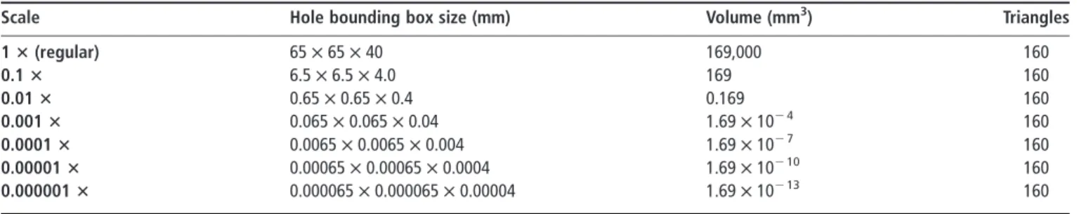
VAPs are particularly useful in the assembly planning of small and micro-components. However, each PSE has a minimum object’s size where the collision detection is accurate. Small objects may produce unreal collision responses leading to virtual assembly process difficult to be completed. Thus, the objective of this test is to evaluate the PSE performance when carrying out haptic virtual assemblies of small and very small size components. In this test the peg-in-hole assembly task is performed using seven levels of scale (Table IV ). A graphic comparison of the first four scales can be observed in Figure 8. TCTand physics simulation time (PST) are the evaluation parameters.
Figure 3 Balancing test
Figure 4 Pile of boxes assembly test Figure 2 Free-fall test
4.7 Bearing puller assembly test
The assembly analysis of real complex components is the main purpose of any VAP. Therefore, the objective of this test is to evaluate the overall PSE performance when carrying out haptic virtual assemblies representing real complex components. Thus, the assembly of a bearing puller is considered and comprises six
parts with cylindrical features: puller base, puller screw, two arms and two pins (Figure 9(a)). The puller base is defined as the base part and remains static during the assembly process (Figure 9(b)). TCT, force feedback and physics simulation time are considered as the evaluation parameters. The real assembly was also performed for comparison purposes (Figure 9(c)).
4.8 Bench vice assembly test
The objective of this test is to evaluate the PSE performance when carrying out virtual assemblies representing real components with complex features. For this, the bench vice assembly that comprises four parts: a large jaw, a short jaw, a screw and a pin, was considered (Figure 10(a)). The large jaw comprises a slider where the short jaw must be slipped on. This imposes different simulation conditions than cylindrical features, resulting in a multidirectional collision response. If the PSE is not effective in handling this condition the collision response may be excessive impeding the assembly. The large jaw is defined as the base part and remains static during the assembly process (Figure 10(b)). TCT, force feedback and physics simulation time are considered as the evaluation parameters. The real assembly of the bench vice was also considered (Figure 10(c)).
5. Results and discussion
5.1 Free-fall test resultsThe results regarding to the influence of the number of triangles (shape complexity) on the integrator performance are shown in Figure 11. It can be observed that when the number of triangles of the model is less than 300, e.g. box, pin and gear, the integrator performance of PhysX is not affected, whereas in the case of Bullet an increase of up to 43 per cent in the gear free-fall time is observed with respect to the pin test. However, when the Figure 5 Packing box assembly test
Figure 6 Gear oil pump virtual assembly task
Table III Levels and weights (N) of pump components
Level Housing (N) Large gear (N) Short gear (N) Bearings (N)
L1 0.02 0.02 0.02 0.02 L2 1.3 0.17 0.13 0.1 L3 3.3 0.41 0.34 0.29 L4 .4 0.82 0.66 0.51 L5 .4 1.11 0.9 0.69 L6 .4 1.64 1.31 1.01 L7 .4 2.23 1.81 1.34 L8 .4 3.24 2.71 1.47 Real 16.7 6.7 5.2 1.6
Figure 8 Scaled hole: 1 £ , 0.1 £ , 0.01 £ and 0.001 £ Table IV Scale levels
Scale Hole bounding box size (mm) Volume (mm3) Triangles
1 3 (regular) 65 £ 65 £ 40 169,000 160 0.1 3 6.5 £ 6.5 £ 4.0 169 160 0.01 3 0.65 £ 0.65 £ 0.4 0.169 160 0.001 3 0.065 £ 0.065 £ 0.04 1.69 £ 1024 160 0.0001 3 0.0065 £ 0.0065 £ 0.004 1.69 £ 1027 160 0.00001 3 0.00065 £ 0.00065 £ 0.0004 1.69 £ 10210 160 0.000001 3 0.000065 £ 0.000065 £ 0.00004 1.69 £ 10213 160
Figure 9 Bearing puller
(a) (b) (c)
Notes: (a) Virtual parts; (b) virtual assembly; (c) real assembly Figure 10 Bench vice assembly
(a) (b) (c)
object comprises around 2,000 triangles, i.e. the pump housing, the integrator performance is greatly affected. An increase of about 60 per cent in the free-fall time is observed when using Bullet and 100 per cent when using PhysX, with respect to the gear test. The maximum standard deviation (SD) obtained with Bullet was 0.059 s, indicating that all the tests have excellent repeatability. The maximum SD obtained with PhysX was 0.293 s, corresponding to the housing test. These results indicate that PhysX is greatly affected by shape complexity. Moreover, the free-fall times values are smaller and closer to the theoretical time (0.316 s) using Bullet than PhysX. It is important to mention that although the falling time is affected by several parameters such as simulation time step, CPU characteristics, system configuration, etc. the previous tests were performed in equal conditions for both PSEs, i.e. same CPU, same time step, etc.
In order to quantify the influence of the haptic loop on the integrator performance, a second set of tests were carried out. In these experiments, the free-fall tests were first performed without the haptic rendering loop, i.e. only physics þ graphics, and afterwards the tests were repeated with the haptic rendering loop running, i.e. haptics þ physics þ graphics. Table V shows the percentage increase in the free-fall time when the haptic rendering loop is active. Bullet exhibited a time increment of up to 50 per cent, while PhysX showed a maximum time increment of 2 per cent. This suggests that the integrator method of PhysX is more suitable to be used with haptics.
5.2 Balancing test results
The balance tilt angle was measured over one minute after the release of the two spheres. If the tilt angle at the end of a test was smaller than 18, then the system was considered to be balanced. When the angle was larger than 18 but smaller than 58, the reaction forces tend to be slightly different on each side of the balance and the system tilts to one side. In this case the result is expressed as “left” or “right”, depending on the inclination of the balance. Finally if the tilt angle was larger than 58, then the system was considered unbalanced and the result is expressed as “left þ ” or “right þ ”. Each test was performed five times for
each PSE and each collision shape representation algorithm. In order to validate the results, the positions of the spheres were exchanged from the left side to the right side and vice versa.
Table VI shows the results of the balancing test. It can be observed that when primitives are used in both PSEs, Bullet and PhysX, the balance remained in equilibrium (horizontal) for all the repetitions. This suggests that the reaction force and collision response when using primitives is stable and precise. When using GIMPACT, ConvexFT or HACD the balance tilted to both sides, indicating that the collision response is not very precise. This is caused by the different number and characteristics of contact points. A contact point produces a force or impulse with a defined magnitude and direction. Two objects with the same shape can have different contact points defined by the object’s triangular mesh, position and orientation.
5.3 Pile of boxes results
Two collision shape representation algorithms were used for each PSE: GIMPACT for Bullet, ConvexFT for PhysX and HACD for both. Five repetitions were performed for each collision shape and each PSE; the results are shown in Table VII. It was observed that when Bullet-HACD was used and the boxes had dynamic behaviour, the collision response showed low stability, allowing the piling of only ten boxes. In the case of Bullet-GIMPACT, it was not possible to perform the task because the collision response was excessive, producing instabilities that prevented placing a box on the top of another. PhysX showed better stability even when the assembled boxes had dynamic behaviour. In this case the 15 boxes could be piled using both representations.
5.4 Packing box test results
In this test the HACD representation algorithm was used to create the collision shapes. Five repetitions were performed for each PSE. PhysX led to the minimum TCT, 2:09.7 min (3.8 s SD), whilst Bullet posted 4:17.4 min (16.2 s SD). Collision response and assembly stability were qualitatively evaluated according to Table VIII. The best stability of the final assembly was observed when using PhysX, but the best collision response of manipulated objects was observed when using Bullet.
5.5 Weight perception test results
The collision shapes were created using triangular mesh representation algorithms, i.e. GIMPACT for Bullet and ConvexFT for PhysX. Five repetitions were carried out for
Table V Percentage increase of the free-fall time
Object Bullet (%) PhysX (%)
Box 3.65 0.195
Cylinder 3.8 0.139
Gear 50.42 2.16
Table VII Pile of boxes assembly, TCT results
Representation/PSE Bullet (min) PhysX (min)
HACD 02:47.2 (35.2 s SD) 1:57.3 (0.3 s SD)
GIMPACT/ConvexFT Not feasible 1:54.3 (13.6 s SD)
Table VI Balancing test results using Bullet physics
PSE Collision shape Left 1 Left Balanced Right Right 1
Bullet Primitive 0 0 5 0 0 PhysX Primitive 0 0 5 0 0 Bullet GIMPACT 2 0 1 1 1 PhysX ConvexFT 4 0 0 0 1 Bullet HACD 3 0 2 0 1 PhysX HACD 3 1 0 0 0
Figure 11 Free-fall time with respect to shape complexity (number of triangles) 4.5 4.0 Bullet PhysX 3.5 3.0 2.5 2.0 1.0 1.5 0.5 0.0
Box (12) Pin (44) Gear (276)
Number of triangles
Housing(1934)
F
ree-fall time (sec
each PSE. The results are shown in Figure 12, where the mean TCT using PhysX is shown as a red dashed line whereas the mean TCT using Bullet is shown as a green dotted line.
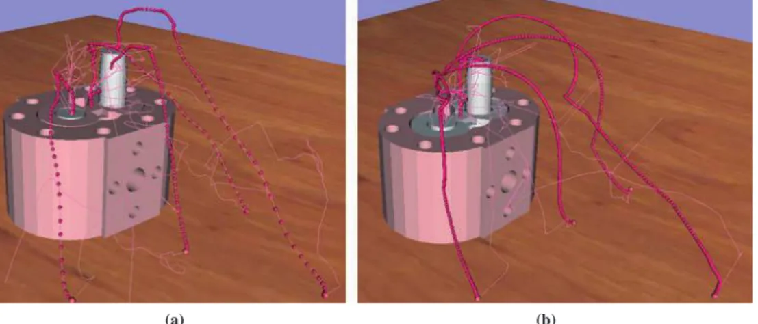
The maximum TCT value, 2:09.7 min (41.7 s SD), corresponds to the use of PhysX and weight level L8, whereas the minimum TCT value, 49.7 s (7.3 s SD), corresponds to the use of Bullet and weight level L1. The average TCT of the real assembly process is 37 s (12.79 s SD). The chronocyclegraphs of the pump assembly test using weight levels L1 and L8 are shown in Figure 13(a) and (b), respectively. The red spheres represent the manipulation path of the virtual objects and the distance between each sphere represents the motion speed. Weight level L8 exhibited a lower speed than weight level L1. Thus, it can be said that as the inertia of virtual objects increases, the manipulation speed decreases and therefore the TCT increases, just as it happens in the real world.
5.6 Size test results
Two kinematics configurations were evaluated: 1 dynamic; and
2 static behaviour of the box (i.e. base part).
Five repetitions were performed for each scale, each PSE and each kinematic configuration. The results are shown in Table IX. The data marked with*indicate that the collision detection was not accurate and a light penetration between models was observed. “NP” indicates that the assembly was not possible due to excessive penetration between models.
When using Bullet with dynamic behaviour the assembly could be performed using all sizes, even for the smallest scale of 0.0000001 £ . However, a satisfactory performance of this configuration was observed only at scale of 0.001 £ or larger, for smaller scales the PST increases. In the case of PhysX with dynamic behaviour, the minimum scale for a satisfactory performance was 0.1 £ . At 0.01 £ scale the collision detection was not accurate and the PST increased. In the case of Bullet
with static behaviour, the assembly could be performed with a satisfactory performance at scales of 0.001 £ or larger; smaller scales resulted in the lack of collision detection and response. When using PhysX with static behaviour, the assembly could be carried out with a satisfactory performance using a 0.0001 £ scale or larger.
5.7 Bearing puller assembly results
Triangular mesh representation algorithms – GIMPACT and ConvexFT – were used to create the collision shapes. Six repetitions were carried out for each PSE using a one handed configuration for virtual object manipulation. The results are shown in Table X.
It can be observed that the smallest TCT was obtained when using Bullet. The mean and maximum forces are smaller when using Bullet than when using PhysX. This suggests that Bullet offers a more stable collision response and object manipulation than PhysX. The PST is a measure of the PSE update rate, both Bullet and PhysX exhibited similar simulation times, around 4.5 ms. The assembly of the real component took an average TCT of 17.5 s (2 s SD), smaller than the virtual TCT. 5.8 Bench vice assembly results
In the case of the bench vice assembly, the collision shapes were created using the ConvexFT algorithm in PhysX, but very strong collision responses between the short jaw and the large jaw were produced and the assembly of the two components was impossible. To overcome this problem, the collision shapes in PhysX were created using the HACD algorithm for dynamic objects, and static triangular meshes for static parts. Six repetitions were carried out for each PSE using a one handed configuration for virtual objects manipulation. The results are shown in Table XI.
The results show that TCT, mean force and maximum force are smaller when using Bullet. This suggests that a better manipulation of objects and more stable collision response can be obtained with Bullet. The use of static objects in PhysX led to a significantly smaller PST (0.93 ms) than in Bullet (4.37 ms). However, although PhysX offers a better simulation update rate, the collision detection and collision shape representation algorithms must be improved. The assembly of the real component was also performed, resulting in a TCT of 10.9 s (1.0 s SD), smaller than the TCT of the virtual assembly. 5.9 Results summary
A summary of results is presented in Table XII. From this table it is notable that PhysX displayed better performance than Bullet in simple assembly tasks such as the pile of boxes or the packing box, where simple, non-convex models, were used. However, for more complex models or assembly tasks – such as the gear oil pump, bearing puller or bench vice assembly – Bullet showed better performance, TCT and collision responses, than PhysX. It can also be seen that in the free-fall test the integrator method of Bullet is less sensitive to complex Table VIII Qualitative evaluation parameters
Value Collision response Assembly stability
3 The response is similar to real world The objects remain static in the assembly position
2 Strong responses or penetration, occasionally The objects shiver in the assembly position
1 Excessive response, objects are launched away Some objects drop out of assembly position
0 No collision response, excessive penetration The assembly explodes
Figure 12 Oil pump assembly with different weight levels
0:00.0 0 1 2 3 4 weight level 5 6 7 8 0:17.3 0:34.6 0:51.8 1:09.1 1:26.4 1:43.7 2:01.0 2:18.2 Real 1Hand Bullet Physx
models than the integrator of PhysX. However, PhysX is more independent of the haptic rendering loop. From the balancing test it can be concluded that only the primitive collision shape representation methods resulted in a good performance for both
Bullet and PhysX. The rest of the collision shape representation algorithms, i.e. HACD, GIMPACT and ConvexFT, showed different collision responses in each test.
6. Conclusion
A new methodology to evaluate the performance of PSEs in haptic virtual assembly environments has been proposed. This methodology comprises eight tests with variable geometric and dynamic complexity to assess the performance of any PSE. The proposed methodology was implemented and validated by assessing the performance of Bullet v2.81 and PhysX v2.8.4. In all the tests the haptic device and/or haptic rendering loop was activated in order to analyse its effect on the PSE performance. The results of the validation suggested that for simple assembly tasks that involve non-complex geometries, PhysX offers a better performance than Bullet. Nevertheless, when the assembly comprises more complex shapes, e.g. non-convex objects, Bullet has better performance. PhysX offers a better simulation update rate and final assembly stability than Bullet. It was also observed that the TCT is directly affected by the weight of virtual objects; as the inertia of virtual objects increases, the manipulability and assembly performance decrease. Regarding objects’ size, Bullet offers the ability to handle collisions for smaller dynamic components than PhysX. Finally it can be concluded that the PSE greatly affects the performance and accuracy of virtual assembly systems. However, by using the proposed methodology the strengths and limitations of PSEs used in VAPs can be identified. The characterization or evaluation of PSEs will lead to the design of faster and more reliable systems which can be used in real applications.
Future work considers a more comprehensive study to use the proposed methodology in others VAPs and to evaluate other PSEs. Also the influence of collision shape representation algorithms on the performance of haptic virtual assembly tasks must be considered. In some of the tests performed during this evaluation, strong collision responses were produced occasionally when virtual objects had contact. In order to evaluate these strange responses, a study to find a way to measure the fluctuations in the excitation functions of dissipative collisions is currently under development.
Figure 13 Oil pump assembly chronocyclegraphs
(a) (b)
Notes: (a) Weight L1; (b) weight L8 Table IX Size test results
Bullet – dynamic PhysX – dynamic Bullet – static PhysX – static Scale TCT (s) PST (ms) TCT (s) PST (ms) TCT (s) PST (ms) TCT (s) PST (ms) 1 3 6.1 1.80 12.7 16.46 11.2 2.36 5.2 0.67 0.1 3 5.4 1.84 6.2 11.02 9.1 2.40 5.2 0.59 0.01 3 5.1 1.80 11.0* 20.12 12.0 3.44 5.5 0.52 0.001 3 4.4 1.96 NP NP 7.7 2.72 5.7 0.54 0.0001 3 4.0 5.05 NP NP NP NP 8.0 0.54 0.00001 3 4.7 5.24 NP NP NP NP 6.3* 1.05 0.000001 3 4.9* 4.85 NP NP NP NP NP NP 0.0000001 3 6.1* 6.30 NP NP NP NP NP NP
Table X Measured parameters in the bearing puller assembly simulation
Bullet PhysX
Parameter Value SD Value SD
Assembly time, TCT (min) 01:19.3 00:11.8 03:38.7 00:31.5
Mean force feedback (N) 0.55 0.098 0.62 0.097
Max force feedback (N) 1.88 0.16 3.55 0.34
Physics simulation time, PST (ms) 4.65 0.97 4.43 0.35
Table XI Bench vice assembly simulation results
Bullet PhysX
Parameter Value SD Value SD
Assembly time (min) 01:15.3 00:09.5 01:18.2 00:21.6
Mean force (N) 0.46 0.084 0.58 0.044
Max force (N) 1.89 0.24 2.76 1.14
References
Aleotti, J. and Caselli, S. (2011), “Physics based virtual reality for task learning and intelligent disassembly planning”, Virtual Reality, Vol. 15, pp. 41-54.
Baraff, D. (1989), “Analytical methods for dynamic simulation of non-penetrating rigid bodies”, Computer Graphics, Vol. 23, pp. 223-232.
Baraff, D. (1995), “Interactive simulation of solid rigid bodies”, IEEE Computer Graphics and Applications, Vol. 15 No. 3, pp. 63-75.
Bhatti, A., Nahavandi, S., Khoo, Y.B., Creighton, D., Anticev, J. and Zhou, M. (2009), “Haptically enable interactive virtual assembly training system development and evaluation”, SIMTECT 2009: Proceedings of the 2009 International Design Engineering Technical Conferences & Computers and Information in Engineering Conference, SIMTECT, Adelaide, South, pp. 1-6.
Boeing, A. and Bra¨unl, T. (2007), “Evaluation of real-time physics simulation systems”, Graphite’07 Proc. of the 5th Int. Conf. on Comp. Graph. and Int. Tech., Australia and SW Asia, pp. 281-288.
Bordegoni, M., Cugini, U., Belluco, P. and Aliverti, M. (2009), “Evaluation of a haptic-based interaction system for virtual manual assembly”, Virtual and Mixed Reality, LNCS 5622, Springer, Berlin, pp. 303-312.
Chamaret, D., Ullah, S. and Naud, P.M.R. (2010), “Integration and evaluation of haptic feedbacks: from CAD models to virtual prototyping”, International Journal on Interactive Design and Manufacturing (IJIDeM), Vol. 4, pp. 87-94.
Chen, C.J., Ong, S.K., Nee, A.Y.C. and Zhou, Y.Q. (2010), “Haptic-based interactive path planning for a virtual robot arm”, International Journal on Interactive Design and Manufacturing (IJIDeM ), Vol. 4, pp. 113-123.
Cheng-Jun, C., Yun-feng, W. and Niu, L. (2010), “Research on interaction for virtual assembly system with force feedback”, ICIC’10 Proceedings of the 2010 Third International Conference on Information and Computing, Vol. 2, pp. 147-150.
Christiand and Yoon, J. (2011), “Assembly simulations in virtual environments with optimized haptic path and sequence”, Robotics & Computer-Integrated Manufacturing, Vol. 27, pp. 306-317.
Coumans, E. and Victor, K. (2007), “COLLADA physics”, Web3D’07 Proceedings of the Twelfth International Conference on 3D Web Technology, pp. 101-104.
Coutee, A.S., McDermott, S.D. and Bras, B. (2001), “A haptic assembly and disassembly simulation environment and associated computational load optimization techniques”, Journal of Computing and Information Science in Engineering, Vol. 1, pp. 113-122. Garbaya, S. and Zaldivar-Colado, U. (2007), “The affect
of contact force sensations on user performance in virtual assembly tasks”, Virtual Reality, Vol. 11, pp. 287-299.
Garbaya, S. and Zaldivar-Colado, U. (2009), “Modeling dynamic behavior of parts in virtual assembly environment”, Proceedings of the ASME/AFM 2009 World Conference on Innovative Virtual Reality WINVR2009, Chalon-sur-Saoˆne, France, 25-26 February.
GIMPACT (2011), “GIMPACT: Geometric Tools for VR”, available at: http://gimpact.sourceforge.net/reference_html/ features.html
Glondu, L., Marchal, M. and Dumont, G. (2010), “Evaluation of physical simulation libraries for haptic rendering of contacts between rigid bodies”, Proceedings of ASME, WINVR 2010, Ames, IA, USA, WINVR201-3726, pp. 41-49, 12-14 May.
Gonzalez, G., Medellin, H.I., Lim, T. and Ritchie, J.M. (2012), “3D object representation for physics simulation engines and its effect on virtual assembly tasks”, Proceedings of the ASME 2012 IDETC/CIE, Chicago, IL, USA, 12-15 August.
Gonza´lez-Badillo, G., Medellı´n Castillo, H.I. and Lim, T. (2013), “Development of a haptic virtual reality system for assembly planning and evaluation”, 3rd Iberoamerican Conference on Electronics Engineering and Computer Science, CIIECC2013, Procedia Technology, Vol. 7, Elsevier, Amsterdam, pp. 265-272.
Table XII Summarized results of the evaluation tests
Test Bullet v2.81 PhysX v2.8.4 Evaluation parameter
Free-fall, shape complexity 60% 100% Percentage of increase on falling time
Free-fall, haptic rendering loop 50.42% 2.16% Percentage of increase on falling time
Balancing Only stable for primitives Stability of the balance, tilt angle
Pile of boxes (HACD) 02:47.2 min 01:57.3 min Assembly time (TCT), convex collision shape
Pile of boxes (triangular mesh) Not possible 01:54.3 min Assembly time (TCT), triangular mesh
Packing box 04:17.4 min 02:09.7 min Assembly time (TCT)
Packing box, stability 2 3 Qualitative value of final assembly stability
Packing box, collision response 3 2 Qualitative value of collision response
Weight perception 0:49.7 min 01:04.2 min Minimum TCT at weight level L1 (min)
Size test dynamic 0.065 £ 0.065 £ 0.04 mm 6.5 £ 6.5 £ 4.0 mm Minimum size of hole bounding box
Size test static 0.065 £ 0.065 £ 0.04 mm 0.0065 £ 0.0065 £ 0.004 mm Minimum size of hole bounding box
Bearing puller assembly 01:19.3 min 03:38.7 min TCT
Bearing puller assembly 4.65 ms 4.43 ms Physics simulation time
Bench vice assembly 01:15.3 min 01:18.2 min TCT
Bench vice assembly 4.37 ms 0.93 ms Physics simulation time
Note: Best performance italicised
Gupta, R., Whitney, D. and Zeltzer, D. (1997), “Prototyping and design for assembly analysis using multimodal virtual environments”, Computer-Aided Design, Vol. 29 No. 8, pp. 585-597.
Gutie´rrez, T., Rodrı´guez, J., Ve´laz, Y., Casado, S., Suescun, A. and Sa´nchez, E.J. (2010), “IMA-VR: a multimodal virtual training system for skills transfer in industrial maintenance and assembly tasks”, paper presented at 19th IEEE International Symposium on Robot and Human Interactive Communication, Principe di Piemonte, Viareggio, Italy, 12-15 September.
Hassan, S. and Yoon, J. (2010), “Haptic based optimized path planning approach to virtual maintenance assembly/ disassembly (MAD)”, paper presented at 2010 IEEE/RSJ International Conference on Intelligent Robots and Systems, Taipei, Taiwan, 18-22 October.
Howard, B.M. and Vance, J.M. (2007), “Desktop haptic virtual assembly using physically based modeling”, Virtual Reality, Vol. 11, pp. 207-215.
Huang, F., Gillespie, R.B. and Kuo, A. (2002), “Haptic feedback and human performance in a dynamic task”, Proceedings of the 10th Symposium on Haptic Interfaces for Virtual Environments and Teleoperator Systems (HAPTICS’02), IEEE, New York, NY, pp. 24-31.
Iacob, R., Mitrouchev, P. and Le´on, J. (2011), “Assembly simulation incorporating component mobility modeling”, International Journal on Interactive Design and Manufacturing (IJIDeM), Vol. 5 No. 2, pp. 119-132.
Jayaram, S., Connacher, H. and Lyons, K. (1997), “Virtual assembly using virtual reality techniques”, Computer-Aided Design, Vol. 29 No. 8, pp. 575-584.
Jayaram, S., Jayaram, U., Wang, Y., Tirumali, H., Lyons, K. and Hart, P. (1999), “VADE: a virtual assembly design environment”, Computer Graphics and Applications, IEEE, Vol. 19 No. 6, pp. 44-50.
Ji, J., Lee, K.M. and Zhang, S. (2011), “Cantilever snap-fit performance analysis for haptic evaluation”, Journal of Mechanical Design, ASME, Vol. 133 No. 12, pp. 1-8.
Ladeveze, N., Fourquet, J. and Puel, B. (2010), “Interactive path planning for haptic assistance in assembly tasks”, Computers & Graphics, Vol. 34, pp. 17-25.
Laurell, B. (2008), “The inner workings of real-time physics simulation engines”, paper presented at IRCSE’08 IDT Workshop on Interesting Results in Computer Science and Engineering, Ma¨lardalen University, Vasteras.
Lecuyer, A., Kheddar, A., Coquillart, S., Graux, L. and Coiffet, P. (2001), “A haptic prototype for the simulations of aeronautics mounting/unmounting operations”, paper presented at 10th IEEE, Robot and Human Interactive Communication.
Lim, T., Ritchie, J.M., Dewar, R.G. and Corney, J.R. (2007), “Factors affecting user performance in haptic assembly”, Virtual Reality, Vol. 11, pp. 241-252.
Liu, M., Wang, D. and Zhang, Y. (2010), “A novel haptic rendering algorithm for stable and precise 6-dof virtual assembly”, Proceedings of the ASME 2010 World Conference on Innovative Virtual Reality, Ames, IA, USA, WINVR2010-3724, 12-14 May.
Mamou, K. and Ghorbel, F. (2009), “A simple and efficient approach for 3D mesh approximate convex decomposition”, paper presented at 16th IEEE International Conference on Image Processing (ICIP’09), Cairo, 7-10 November.
Ritchie, J.M., Lim, T., Sung, R.S. and Medellin, H. (2008a), “Generation of assembly process plans and associated Gilbreth motion study data”, Proceedings of the Second Virtual Manufacturing Workshop, EU Intuition VR Network Conference Intuition, Turin, Italy, 6-8 October.
Ritchie, J.M., Lim, T., Sung, R.S., Corney, J.R. and Rea, H. (2008b), “The analysis of design and manufacturing tasks using haptics and immerse VR: some case studies”, in Doru, T. and Angelos, A. (Eds), Product Engineering: Tools and Methods Based on Virtual Reality, Springer, Dordrecht, pp. 507-522.
Ruspini, D.C. and Khatib, O. (1997), “Collision/contact models for the dynamic simulation of complex environments”, 9th International Symposium of Robotics Research (ISRR’99), Snowbird, pp. 185-195.
Sato, K., Date, H. and Onosato, M. (2011), “Fast matching, combinations extraction and configuration of mesh models using graph-based feature representation”, International Journal on Interactive Design and Manufacturing (IJIDeM), Vol. 5, pp. 133-136.
Seth, A., Su, H.J. and Vance, J.M. (2006), “SHARP: a system for haptic assembly & realistic prototyping”, paper presented at ASME Design Engineering Technical Conferences and Computers and Information in Engineering Conference, Philadelphia, PA, USA.
Seth, A., Vance, J.M. and Oliver, J.H. (2011), “Virtual reality for assembly methods prototyping: a review”, Virtual Reality, Vol. 15, pp. 5-50.
Seugling, A. and Ro¨lin, M. (2006), “Evaluation of physics engines and implementation of a physics module in a 3D authoring tool”, Master’s thesis, Computing Science, Umea University, Umea.
Tching, L., Dumont, G. and Perret, J. (2010), “Interactive simulation of CAD models assemblies using virtual constraint guidance”, International Journal on Interactive Design and Manufacturing (IJIDeM), Vol. 4 No. 2, pp. 95-102.
Wan, H., Gao, S., Peng, Q., Dai, G. and Zhang, F. (2004), “MIVAS: a multi-modal immersive virtual assembly system”, Proceedings of the ASME Design Engineering Technical Conference, Salt Lake City, UT, USA, pp. 113-122.
Wang, Y., Jayaram, S. and Jayaram, U. (2001), “Physically based modeling in virtual assembly”, Int. J. of Virtual Reality, Vol. 5 No. 1, pp. 1-14.
Xia, P., Lopes, A.M. and Restivo, M. (2011), “Design and implementation of a haptic-based virtual assembly system”, Assembly Automation, Vol. 31 No. 4, pp. 369-384.
Xia, P., Lopes, A.M., Restivo, M.T. and Yao, Y. (2012), “A new type haptics-based virtual environment system for assembly training of complex products”, The International Journal of Advanced Manufacturing Technology, Vol. 58 Nos 1/4, pp. 379-396.
Zaldivar-Colado, U. and Garbaya, S. (2009), “Virtual assembly environment modelling”, Proceedings of the ASME/AFM 2009 World Conference on Innovative Virtual Reality WINVR2009, Chalon-sur-Saoˆne, France, 25-26 February.
Zerbato, D., Baschirotto, D., Baschirotto, D., Botturi, D. and Fiorini, P. (2011), “GPU-based physical cut in interactive haptic simulations”, International Journal CARS, Vol. 6, pp. 265-272.
Further reading
Giachristis, C., Barrio, J., Ferre, M., Wing, A. and Ortego, J. (2009), “Evaluation of weight perception during unimanual and bimanual manipulation of virtual objects”, Third Joint
Eurohaptics Conference and Symposium on Haptic Interfaces for Virtual Environments and Teleoperator Systems, Salt Lake City, UT, USA, 18-20 March, pp. 629-634.
Tzafestas, C.S. (2003), “Whole hand kinesthetic feedback and haptic perception in dextrous virtual manipulation”, Transactions on Systems, Manufacturing and Cybernetics, Part A: Systems and Humans, IEEE, Vol. 33 No. 1, pp. 100-113.
Corresponding author
Germanico Gonzalez-Badillo can be contacted at: [email protected]