Science Arts & Métiers (SAM)
is an open access repository that collects the work of Arts et Métiers Institute of Technology researchers and makes it freely available over the web where possible.
This is an author-deposited version published in: https://sam.ensam.eu
Handle ID: .http://hdl.handle.net/10985/10234
To cite this version :
Frédéric DAU, Laurent MAHEO, Ba Danh LE, Jérémie GIRARDOT - A promising way to model damage in composite and dry fabrics using a Discrete Element Method (DEM) - 2014
Any correspondence concerning this service should be sent to the repository Administrator : [email protected]
COVER SHEET
Title: A promising way to model damage in composite and dry fabrics using a
Discrete Element Method (DEM)
Authors : Frédéric Dau Laurent Mahéo Ba Danh Le Jérémie Girardot
ABSTRACT
A promising way to model fracture mechanics with the use of an original Discrete Element Method (DEM) is proposed. After proving the ability of the method to capture kinetic damage induced by cracking phenomena in brittle materials such as silica [1], taking advantage of the method for composite materials applications is the main purpose of this work. This paper highlights recent developments to prove capabilities of the DEM and to give some answers to challenges : i) use the present DEM to model damage mechanisms (matrix cracking, debonding, fiber break and delamination) in a composite material ii) deal with impact applications using the DEM. All developments are made in the home made software GRANOO (GRANular Objet Oriented) [2]. The capability of the DEM to model matrix cracking, debonding and fiber break is first demonstrated on a so-called representative elementary volume (REV) made of a fiber flooded in a matrix. Modelize the REV with DEM and retrieve suitable homogenized properties is the first challenge reached. Secondly, the ability of the method to capture matrix cracking, debonding and fiber break is qualitatively demonstrated through basic static simulations performed on the REV. The ongoing developments to improve are presented. Then, the Double Cantilever Beam (DCB) test using Discrete Element (DE) is investigated. Contact cohesive laws are identified from experiments and implemented in GRANOO. Simulations of DCB test using DEM are then performed. Results are discussed and ways of improvements are proposed. Finally, the ability of the DEM to simulate impact damage on textile is pointed out. Numerical investigations are based on Ha-Minh & co. Works in [3, 4] taken for reference. The weaving is exactly reproduced with DE. The contact between yarns is naturally taken into account in the DEM. The promising results are commented and the on going developments are exposed.
_________________________________
Frederic Dau, associate professor
Laurent Maheo, graduate student researcher (during works), associate professor (now) Ba Danh Le, graduate student researcher
INTRODUCTION
The increasing market of composite in the aeronautical sector in particular imposes statutory requirements for the safety of the properties and the persons. Concerning the composite material, a major industrial stake is to propose a structural material performing against impacts such as falls of tools during the maintenance, tire debris projections or hail storm but also composite textile for the debris containment. Faced with the need to strongly reduce experiments for the benefit of numerical simulations, the issue is then to develop numerical models always more efficient. Then, the trend is to favor multiscale approaches allowing a dialogue between a local damaged zone and the global behavior of the considered structure.
Within this framework, several approaches are proposed in literature [5, 6, 7, 8, 9]. The one developed by the research team in the lab consists in a direct coupling approach between a Discrete Element Method (DEM) [10] in the process zone and a more conventional continuous method, the Constrained Natural Element Method (CNEM) beyond the process zone. This coupling, based on Arlequin technique [11] has already led to very good results in static application of glass indentation [1] and more recently, in dynamic application of a laser impact on glass [12].
The new challenge is now to use the DEM developed in the laboratory [18] to treat the damage propagation in composite material (composite textile, Composite Fiber Reinforced Polymer (CFRC), Composite Fiber Reinforced Ceramic (CFRC)) and then, to deal with the case of impact on composite structure using the arlequin coupling method.
Through this paper, our objective is precisely to prove the DEM capability and its relevance to model the damage propagation in composite, Figure 1. This paper highlights recent and current developments to give some answers to challenges : i) use the present DEM to model damage mechanisms (matrix cracking, debonding, fiber break and delamination) in a composite material ii) deal with impact applications using the DEM. All developments are made in the home made software GRANOO [2].
Figure 1 : Structural failure of the laminated composite material
The first section gives the general concepts of the DEM developed in the laboratory. The second one concerns the geometrical and mechanical modelization of a simple composite media made of a fiber flooded in a matrix, called representative elementary volume (REV), with the DEM. Tensile and shearing tests
on the REV are simulated to assess the homogenized properties. The ability of the method to capture matrix cracking, debonding and fiber break using two failure criterions is also demonstrated through the simulations. The on going developments are presented. The next section focuses on the DCB test performed with the DEM. Contact cohesive laws are identified from experiments and implemented in GRANOO. Results are discussed and the ways of improvements are notified. Finally, impact on textile using the DEM is pointed out in the last section. The way to modelize the dry textile weaving with DE is exposed. The contact between yarns is naturally taken into account in the DEM. Numerical investigations based on Ha-Minh & co. Works in [3, 4] taken for reference are performed. The promising results are commented and the on going developments are exposed. Some conclusions and perspectives complete this paper.
ABOUT THE DEM DEVELOPED IN THE LAB AND CHALLENGES IN COMPOSITE
Origin and evolution
Originally, the DEM permits to model granular medias taking into account the contact between the grains. For instance, it has been useful to treat the friction between two bodies involving a third body [13]. The method has been recently adapted [14] to model continuous media liable to crack under loading. The bet is to use the DEM as an alternative to the continuum damage mechanics and the fracture mechanics to represent damage propagations in materials. The DEM seems to be a relevant method from this point of view.
Scales addressed
The DEM can address several scales depending on the physical phenomenon to highlight. In our applications, it usually takes place at microscale involving discrete element as a cluster of one thousand atoms.
Geometrical and mechanical modeling
The shape of the discrete element (DE) can be chosen. It must be adapted to the problem to deal with. By convenience, spherical DE are employed most of the time but more complex geometries could be however envisaged by the use of Voronoi cells for instance [15, 16]. The DE are characterized by their inertial matrix necessary for dynamic applications aimed. In GRANOO software, an explicit integration scheme, Verlet [17] is used in the DEM method naturally formulated to rather deal with fast dynamic applications. To model the mechanical behavior, cohesive bonds are introduced between the DE at microscale. These bonds can be simple springs or beams [14] for more complex behaviors. The idea is to use the simplest interaction laws as much as possible sufficient to emerge macroscopic behaviors.
In brief, the DE geometry associated with the density carries the inertial quantities whereas the cohesive bonds between DE pilot the behavior.
Challenges in composite
After proving the ability of the method to capture kinetic damage induced by cracking phenomena in brittle materials such as silica [1], the motivation of authors is now to take advantage of the method for composite materials applications. Recent and current developments to face the challenges in composite are reported in the sections below.
FIRST CHALLENGE : MODEL A COMPOSITE MEDIA AND CRACKS PROPAGATIONS WITH THE DEM
Modeling a VER : fiber blooded in matrix
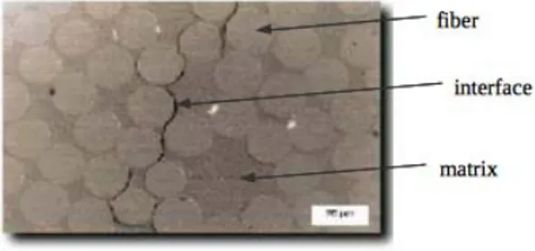
The geometrical modeling of the fiber and the matrix is guided by the following requirements and assumptions: i) use the simplest DE shape, ii) adopt a compatible DE size with the scale of mechanisms to observe, iii) adopt a radius distribution to get a correct representation of the continuous medium (compaction and isotropy), iv) use a sufficient number of DE to ensure the macroscopic results are not sensitive to the discretization.
As mentioned above, DE of spherical shape are used for efficiency reasons. The size of spheres is varying according to a Gaussian distribution. It is chosen in such a way to be able to analyse the mechanisms of degradation at the scale they occur; the matrix micro-cracking, the fiber/matrix debonding and the failure of fibers are the interesting mechanisms. Their number and their size have also to allow a good geometrical representation of the fiber/matrix interface. Practically, building the continuous medium (fiber or matrix) consists of placing at one time a set of DE whose radius has been beforehand chosen according to the required distribution. This stuffing operation is followed by a phase of relaxation to get the best cohesion of the isotropic continuous. The last is governed by two criteria : an optimal rate of compaction (ratio between the volume of spherical DE and the enveloping volume) of 6.3 and a minimal number of coordination (number of contacts by DE) of 6 [18]. Even if the objective at this stage is not to study the degradation of the fiber, its modeling uses the same distribution (casting) of DE as the matrix. This choice allows: i) to avoid prohibitive filling times due to significant differences of size, ii) to get a sufficient fine representation of both the media (fiber and matrix) and the interface. At this stage, being able to represent damage mechanisms at the fiber scale does not present any interest except for the final failure but this will be usefull in the future when intra yarn fissuring will be considered.
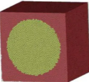
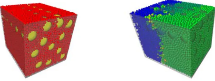
A cubic domain is considered as the representative elementary volume (REV). It is made of a cylindrical carbon fiber flooded in an epoxy matrix. Results are widely available in the literature [19] for such a REV. It also corresponds to a will to avoid too prohibitive times of simulations. The main objective at this stage is to prove the interest of the present DEM for the modeling of the damage mechanisms in composite. For the present REV, the fiber is assumed to be of a cylindrical shape. Its diameter is such as the fraction of fiber is of the order of 51.3%. This corresponds to an arbitrary fixed value. The length of the cell in the fiber direction results from an analysis of sensibility [20]. The Figure 2 presents the elementary volume by distinguishing the cylindrical volume of the fiber of that cubic of the matrix.
Figure 2 : REV discrete modelization using 80 000 DE.
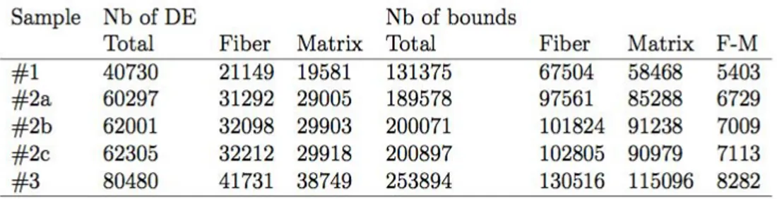
For mechanical modeling, cohesive beams are placed between the fiber DE and the matrix DE but also between the fiber/matrix DE in order to model the behavior of each continuum and the interface. For the REV in Figure 2, 130516 fiber bonds, 115096 matrix bonds and 8282 fiber-matrix bonds were generated between DEs. The beams are supposed to be brittle elastic. Their mechanical properties, introduced at the microscopic scale, are calibrated to find the elastic and failure properties observable at a superior scale. Continum fiber, matrix, and interface elastic and failure properties are mainly adressed. The REV has material properties extracted from literature [21] and listed in Table 1. Thereafter, the subscripts M and µ denote respectively the macroscopic and microscopic variables whereas the
superscripts fib, mat and f−m denote respectively a variable concerning the fiber, the matrix and the fiber-matrix. EM , ρM , νM , σfailM are respectively the macroscopic
Young modulus, the density, the Poisson ratio, the macroscopic stress failure and D, the fiber diameter. Hereafter, isotropic properties are adopted for the carbon fiber by convenience. This assumption has no consequence for primary studies presented here. The transverse isotropy of the carbon fiber will be introduced in future works. Moreover, the interface cohesive bonds are chosen identical to those of the matrix at this stage of work.
Table 1: Calibration of the discrete bounds properties of fiber and matrix.
Homogeneized elastic properties
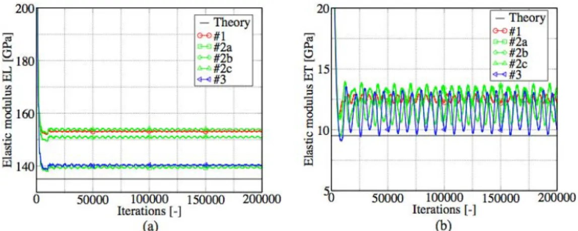
The first motivation is to see if the homogeneized elastic and failure properties are correctly evaluated with the DEM. In this purpose, longitudinal (L) and transversal (T) tensile tests but also in plane (LT) and out of plane (TT’) tests are performed on the REV. The boundary conditions are shown shematically in Figure 3. Five discrete domains, Table 2, are built for simulations to check the influence of the number of DE and the influence of the random position of the DE. A volumic
fraction of fiber of 51.3% is arbitrary chosen.
Figure 3 :Boundary conditions (displacements and loading) for elementary tests.
Table 2: Characteristics of numerical samples
A numerical sensor located at the loading face for each test has been used to measure the evolution of the force in order to calculate a macroscopic stress in the elementary cell. The time step is about 10-9 s. In this validation step, the viscous behavior of the epoxy matrix is first neglected. Only a brittle elastic behavior is taken into account. Figure 4 illustrates typical responses obtained for EL and ET with the DEM. Non-stabilized oscillations subsist due to the explicit time integration and the fact that no numerical or physical damping have been introduced.
Figure 4 : Determination of elastic moduli with elementary tests on the UD composite cell. (a) Determination of EL. (b) Determination of ET .
Table 3 summarizes both the numerical results obtained with the present DEM, analytical ones issued from literature [21, 22, 23] and numerical ones obtained with conventionnal FEM.
Table 3: Elastic properties of the UD composite obtained with the theory, the DEM and the FEM.
The value of elastic properties reported in Table 3 are finally obtained by a sliding average value calculated over several time periods excluding the 10000 first iterations of the loading ramp. Despite the assumptions made by convenience at this stage of work, the results using present DEM are in the same range with the theoretical ones. They confirm a good tendency. They could be significantly improved using more matrix DE in the narrowest area of (a D)/2 size to reduce edge effects for example. Moreover, it can be observed that elastic and shear moduli are rather influenced by the way of building discrete samples than by the number of DE. So, the filling procedure leading to different discrete domains for a same number of DE can be a natural way to take into account material variability.
Cracks propagations capabilities
The ability of the present method to capture cracks propagation is illustrated through the longitudinal tensile test. Two failure criterion based on a stress formulation have been implemented. The simplest one consists in breaking the cohesive beam between two DE when the limit tensile stress is reached in this beam. Then, the failure process is represented by the successive beam failures. It is called breakable bonds failure process (BBF). The second criterion takes into account all the cohevive beam attached to a DE by the use of a virial tensor. This
virial tensor is calculated from the generalized efforts (forces and torques) in the beam by the relation, Eq. 1 :
The failure criterion is satisfied when the microscopic failure limit σfail µ is reached.
It is evaluated for each DE ; that is to say that for a given DE, the bonds (beams) attached to this DE are deleted when the criterion is satisfied but the DE can be stored and the contact with the adjacent DE can be treated. It may be a convenient way to model debris introduced by damages in composite. This failure process is called the removed discrete element failure process (RDEF).
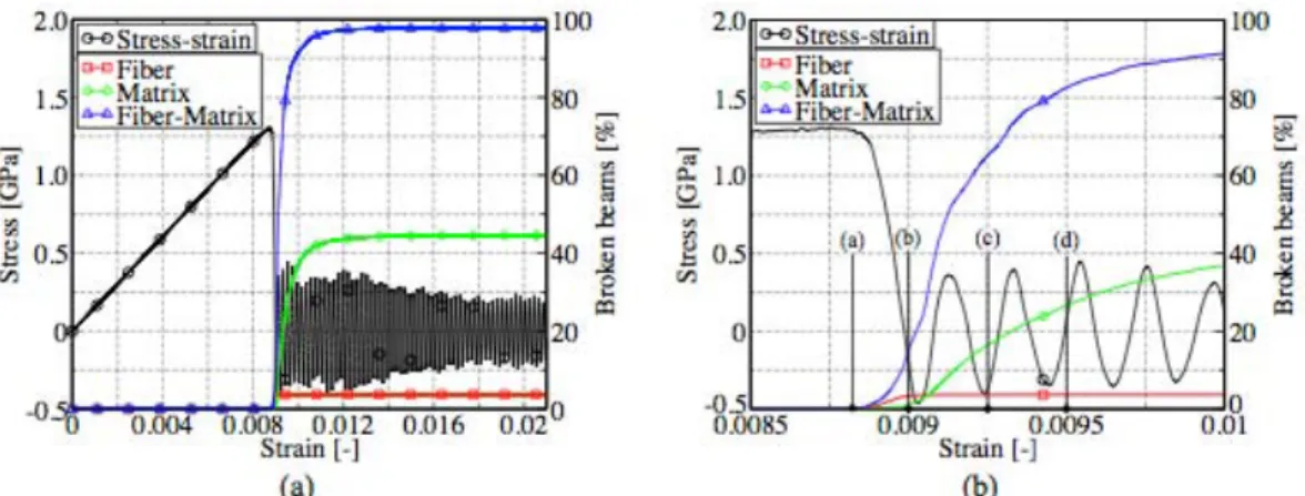
A pure qualitative comparison of the two failure criterions, BBF and RDEF, is given through the tensile test (L). Following illustrations are given using the #2b discrete domain. It is not sought specific physical interpretations at this stage but just to highlight the method capabilities. The evolutions of the broken bonds in matrix, fiber and at interface fiber-matrix are plotted on Figures 5 and 6 in relation with the macroscopic stress-strain curve for respectively BBF and RDEF criterion. The broken bonds are also displayed on Figures 7 and 8 to illustrate the propagation of the failure inside the elementary cell. For clarity, only the fiber-matrix beams and the broken beams in the REV are represented respectively in red and blue color.
Figure 5 : (a) Evolution of % broken beams in matrix, fiber and at the interface with BBF criterion. (b) Zoom of (a) for strains between 0.0085 and 0.01
Figure 6 : (a) Evolution of % broken beams in matrix, fiber and at the interface with RDEF criterion (b) Zoom of (a) for strains between 0.008 and 0.011.
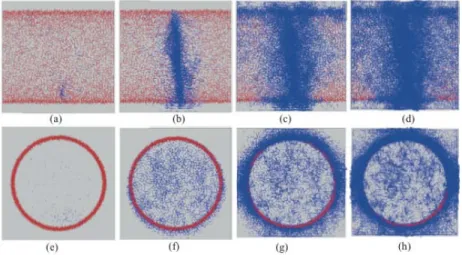
Figure 7 : Display of broken beams (in blue) using BBF criterion at different strain stages – (a,e) εM
= 8.82 · 10-3 (b,f ) εM = 9.00 · 10 -3 (c,g) ε M = 9.25 · 10 -3 (d,h) ε M = 9.50 · 10 -3 (a,b,c,d) Profile views (e,f,g,h) Face views.
Figure 8 : Display of broken beams (in blue) using RDEF criterion at different strain stages - (a,e)
εM = 10.00·10 -3 (b,f) ε M = 10.25·10 -3 (c,g) ε M = 10.50·10 -3 (d,h) ε M = 12.00 · 10 -3 (a,b,c,d) Profile views (e,f,g,h) Face views.
Some qualitative remarks can be done from this test : i) using RDEF criterion, damages appear progressively in the fiber during a longer strain duration than with using BBF criterion ; ii) cracks inititate differently using BBF or RDEF criterion. Indeed, a more local initiation can be noticed using BBF ; iii) using RDEF criterion, the crack mainly propagates through the matrix, see Figures 8(c) and 8(g), whereas it mainly propagates through the interface fiber-matrix with BBF criterion ; iv) the macroscopic failure strain εfailM is higher with the RDEF process than with BBF one.
The same test has been simulated using the other discrete domains presented in Table 2. Table 4 summarizes the macroscopic failure properties obtained. Results appear fairly dispersed. Otherwise, the use of RDEF criterion seems to led to higher values than those obtained with BBf criterion. The theorical macroscopic failure strain values for the present fiber and matrix are respectively εfib
M = 9.6·103 and εmatM = 20.3·103
Table 4 : Failure properties of the UD composite obtained with present DEM.
Current and future works on this first challenge
Developments concern the identification of the cohesive law between fiber and matrix (debonding). Pull-out tests are planned in this purpose. Then, the idea is to model a statistical elementary volume (SEV) made of a few fibers randomly distributed within an elementary volume, Figure 9, using the previous cohesive law for modeling debonding. A focus on this SEV during loading will allow to locally follow the damage evolution (debonding and matrix cracks) and then, degrated properties could be returned to a more global continuous model after homogeneization. For now, the bonds (beams) are identical for a given medium but a natural variability is envisaged in the future by simply varying the properties of these bonds.
Figure 9 : Statistical elementary volume modeled with DEM
Currently, various numerical methods from continuum mechanics have been adapted to study the delamination problems in composite material. The elastic fracture mechanics is one of the most methods used, it considers a composite structure with the pre-cracked, where strain energy release rate is normally used as a criterion for damage propagation [24]. Other studies have used the finite element method (FEM) to study this problem [25, 26, 27] implementing the cohesive zone model into FEM code. This model allows to study the delamination at the interface of the composite when the path is known. However, some difficulties like the re-meshing process during the crack propagation or the mesh sensitivity can occur. Moreover, a very few studies have been conducted concerning delamination under dynamic loading. In addition, the use of cohesive element becomes delicate when the crack path can not be predicted in advance in case of intralaminar fissuration for instance. XFEM methods can be used carefully but they can be very costly. For these reasons, we propose to apply cohesive contact laws (as a cohesive model) in the discrete element method (DEM) to study the delamination of the composite material but also the behavior at the interface fiber/matrix (debonding).
Cohesive contact laws
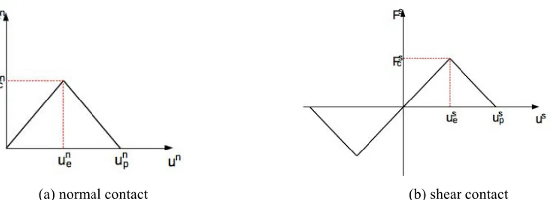
To study the mechanical behavior at interface fiber/matrix, a cohesive contact takes place between a DE belonging to the fiber and a one of the matrix. It is represented by the contact laws presented in Figure 10. A normal or shear cohesive force follows an elastic by piece law. Its value depends on the displacement between two particles in contact at the interface. This contact softening model is similar to the cohesive zone model in the continuum mechanics [28, 29].
(a) normal contact (b) shear contact
Figure 10 : Constitutive behavior of contact softening model.
It describes the behavior of contact bonds in elastic and represents a damage by linearly softening the bond after the contact force reaches the bond strength. In both tensile and shear case, the bond strength decreases to zero when the displacement reaches the maximum displacement uip , i=n or s. uip is related to the fracture energy
release rate G. The crack at interface can propagate in mode I (crack opening), mode
II or mode III (shear) and mixte-mode [30]. The fracture energy release rate for mode I and mode II is expressed by Eq. 2 :
with σi
max= Fimax/S, S=πR2, R=0,5(R1+R2) and R1,R2 are the radius of the particles in
contact, Figure 11.
Figure 11 : Cohesive contact in DEM.
Modeling the DCB test
To study and validate the cohesive contact model in mode I, a Double Cantilever Beam (DCB) test in 3D is firstly investigated. The material used is a UD composite carbon / epoxy. The usefull mechanical properties are: E11=135GPa, E22=9.0GPa,
υ12=0.24. The interface strength is σmax=5.7 MPa, and the strain energy release rate
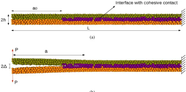
is GI=0.56 N/mm. The DE modeling of the cantilever beam is shown in Figure
12(a) with the geometrical characteristics L = 45 mm (length), b = 6 mm (width) and 2h = 3 mm (thickness). A pre-crack has length of a0 = 0.3L. The number of DE is 40000. A displacement Δ is applied at the left end of the specimen. The cohesive beam micro parameters to represent the homogeneized composite material behavior are classically obtained by a calibration procedure.
(a)
(b)
Figure 12 : Modelisation of DCB test with DEM (a) before loading (b) during loading.
For DCB test, the specimen compliance can be expressed by Eq. 3 :
where a is the crack length and EI is the flexural rigidity of the specimen, Figure 12 (b). When the crack propagates, the fracture enery can be written, Eq. 4 :
G = P2/(2b).dC/da = P2.a2/(b EI) (4) From (3) and (4), the relationship between the force P and the displacement Δ but also the relationship between the displacement Δ and the length of crack a can be deduced during the crack propagation, Eq. 5 :
Results
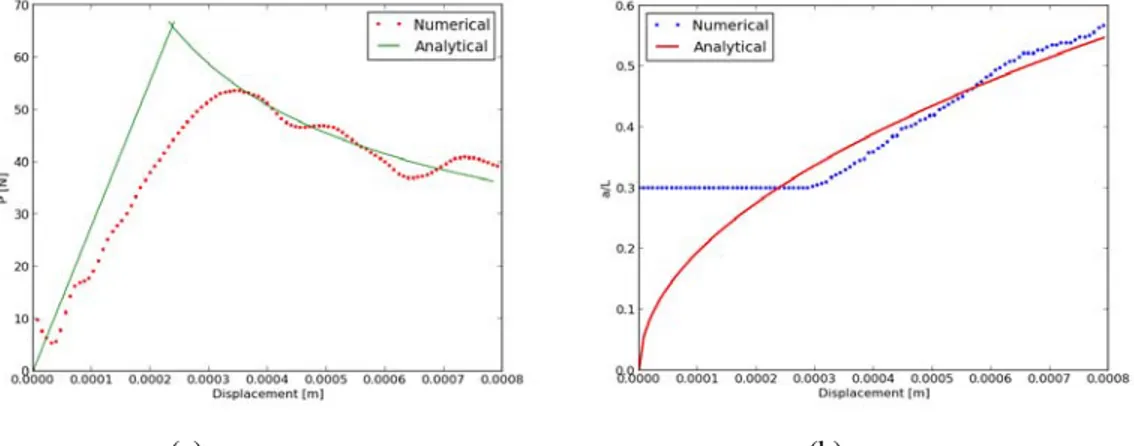
Figures 13 (a) and 13 (b) respectively give the evolution of P=P(Δ) and a/L=a/L(Δ). Analytical and numerical (with present DEM) curves are plotted.
(a) (b)
Figure 13 : (a) P=P(Δ) evolution (b) a/L=a/L(Δ) evolution
Even if improvable during the elastic stage, a good convergency to the analytical model can be observed during the damage of the interface. After the maximum value of P, the cohesive bonds behavior at the interface allow to correctly capture a progressive decrease of the force during the crack, Figure 13 (a). Moreover, the crack propagation follows quite well the theorical curve, Figure 13 (b).
As regarding microscopic behavior at the interface, three zones between the crack tip and the location where the bonds start softening can be distinguished during the mode I delamination : a bond softening zone, a bond broken zone and a damage zone (process zone), Figure 14 (a). The bond softening zone is delimitated by the initial crack tip and the location where the bonds damage (ie for which un between un
e and unp, Figure 10). Figure 14 (b) shows the evolution of the three zones in
relation with the imposed displacement Δ.
(a) (b)
Figure 14: (a) Distinction of damage zones (b) Damage zones lenght
Finally, Figure 15 presents the configuration of the crack propagation and the zone at the crack tip with the singularity stress (process zone).
Figure 15 : Propagation of crack and process zone
Current and future works on this second challenge
Experiments based on [31] are in progress to properly identify the cohesive law in mode I. At the same time, a micro bond test is implemented with DEM, Figure 16, to investigate the fiber/matrix debonding. For now, investigations are mainly numerical based on [32] but experiments are also planned.
Once the normal and cohesive laws properly identified and validated, the end-load split (ELS) test is aimed to validate the model in mode II delaminations. Then, interlaminar (mode I and mode II delaminations) and intralaminar (debonding and matrix cracks in a VES) damages could be considered with DEM.
THIRD CHALLENGE : MODEL IMPACT ON COMPOSITE USING DEM LOCALLY
Simulations of impact on woven materials are already performed using the finite element method [3, 4] and especially shell elements. The shell elements usually model a yarn at the mesoscopic scale. The aim of the present work is to model a dry fabrics with discrete elements to assess the ultimate strenght before yarns rupture but also yarns rupture mechanisms till perforation.
Modeling a dry fabrics
The final interlock 3X to be considered is composed of an interlacing of yarns, Figure 17 (a). Each yarns are composed of approximately 12000 of high resistance carbon fibers. The weft yarns are all straight and the warp yarns are either straight nor deviated through the thickness. Figure 18 shows a simple layout of spherical discrete elements to represent a yarn. All elements have the same diameter and are all in contact but without interpenetration.
(a) (b)
Figure 17 : (a) CT-scan of interlock 3X (b) interlock 3X with DE.
Figure 18 : Model of yarn using DE.
The final geometry is a combination of three different types of yarns : straight yarns in the weft and warp directions and through the thickness yarns. The through the thickness yarns are built using a periodic function ensuring no penetration occurs in the final geometric representation, Figure 17 (b).
As the mesoscopic scale, the yarn is supposed to be elastic fragile. This assumption is relevant regarding to experimental results of a static yarn tensile test [3, 4]. Then, the DE along the longitudinal direction of the yarn are bonded by simple linear breakable springs. The interaction force between two DE, 1 and 2, is expressed by Eq. 6 : F12= Kµ(O1O2 − LO n) with n = O1O2 O1O2 (6) where Kµ represents the microscopic stiffness in N/m of the spring between the two DE, O1 and O2 their gravity centers, L0 the initial distance between O1 and O2. A mesoscopic stiffness KM can be define for a yarn as, Eq. 7 :
Fr=δ⋅ Kµ⋅
n
(7)
where Ly is the yarn length, S its cross section and E the equivalent young modulus of the yarn. As the yarn is modelized by a combination of identical springs arranged in series and parallel, the relation between the mesoscopic and microscopic stiffness depending on the number of spring in series, ns, and in parallel, np can be easily established, Eq.8 : Kµ = ns np KM (8) One can notice that the calibration of the microscopic properties reduced to Kµ in this case is purely analytical. The failure criterion is based on a maximum elongation. The spring failure occurs when its elongation is greater than the one leading to the yarn failure. When it is broken, a spring is disabled for the rest of the computation.
Contact management between interlaced yarns
With present DEM, the contact between DE is naturally taken into account. When an interpenetration is detected (ie when the distance between two DE becomes lower than the sum of the radii of the two DE in contact), the reaction force Fr between the two DE is computed as, Eq. 9 :
Fr=δ⋅ Kµ⋅
n
(9)
where δ represents the interpenetration between two DE. The contact stiffness is assumed to be the same that the microscopic one by convenience. The density 𝜌ED
verifies nEDρEDVED= myarnwhere myarnis the yarn mass, nED and VED denote respectively the number and volume of DE constituting the yarn.
Impact simulation with the DEM : first results
A ballistic impact is simulated with the model defined above refering to works in [3, 4]. The weaving is a 3D interlock with only 3 weft yarns in the thickness. Yarns
are made of Kevlar fibers. The yarn density is 1310 kg/m3 and its young modulus is 62 GPa. The impactor is a rigid sphere of diameter 5,43 mm made in a standard steel of density 7530 kg/m3. It is modeled by a unique DE. The contacts between the impactor and the woven but also the contacts between yarns are taken into account in the calculation. Initial velocity impactor is set to 90 m/s. The size of the weaving is 22 mm x50 mm.
Figure 19 shows the strain evolution at different times during the impact, respectively t=0µs, t=25µs, t=50µs, t=75µs and t=100µs. The maximum
deformation is reached at about t=50 µs and a first yarn brake occurs. Then, the first failures of yarns appear.
Figure 19 : Impact simulation on textile with DEM.
Impact force and impactor velocity are plotted in Figure 20 giving a very good tendancy. Simulations are still in progress to be compared to works in [3, 4]. Results will be presented for the conference.
(a) (b)
Figure 20 : Macroscopic responses during impact (a) Impact force (b) Impactor velocity
Future works on this challenge
Next impacts simulations will be performed on the interlock 3X varying the number of DE and impact conditions to analyse the mass and velocity impactor but also the prestressed effects on global responses and failure progression in the textile. Then, coupling this DE model to a continuous one [10] is intended to be able to modelize larger woven target.
CONCLUSION
Present results clearly show the capabilities of the DEM to deal with composite material and dry fabrics at microscopic and mesoscopic scales. Even if some quantitative considerations are already feasible, qualitative results are mainly demonstrated till now. Current developments focuse on improvements to make quantitative analysis possible.
REFERENCES
[1] M. Jebahi, D. Andre, F. Dau, J.L. Charles, I. Iordanoff, ‘Simulation of Vickers indentation of silica glass’, J Non Cryst Sol 378 (2013) 15-24.
[2] D. Andre, J.L. Charles, I. Iordanoff, I. Terreros, GranOO, a discrete workbench (2013) http://www.granoo.org.
[3] C. Ha-Minh, F. Boussu, T. Kanit, D. Crépin, A. Imad, ‘Analysis on failure mechanisms of an interlock woven fabric under ballistic impact’, engineering Failure Analysis, (2013), pp 2179-2187. [4] C. Ha-Minh, A. Imad, T. Kanit, F. Boussu, ‘Numerical analysis of a ballistic impact on textile fabric’, Int. J. of Mechanical Sciences, 69 (2013), pp 32-39.
[5] F.S. Kelley, Mesh requirements for the analysis of a stress concentration by the specified boundary displacement method, ASME, Proceedings of the Second Computers In Engineering International Conference (1982).
[6] J.B. Ransom, S.L. McCleary, M.A. Aminpour, N.F. Jr. Knight, Computational methods for global/local analysis, Technical Memorandum 107591, (1992) NASA.
[7] K.M. Mao, C.T. Sun, A refined global-local finite element analysis method, Int. Jo. Numer Methods Eng 32 (1991) 29-43.
[8] J.D. Whitcomb, Iterative global/local finite element analysis, Comp. Struct 40(4) (1991) 1027-1031.
[9] K. Terada, N. Kikuchi, A class of general algorithms for multiscale analyses of heteroge- neous media, Comput Methods Appl Mech Eng 190 (2001) 5427-5464.
[10] M. Jebahi, J.L. Charles, F. Dau, L. Illoul, I. Iordanoff, ‘3D coupling approach between discrete and continuum models for dynamic simulations (DEM-CNEM)’, Comput. Methods in Appl. Mech. Eng. 255 (2012) 169-209.
[11] H.B. Dhia, G. Rateau, ‘The Arlequin method as a flexible engineering design tool’, Int. J. Numer. Methods Eng. 62(11) (2005) 1442–1462.
[12] M. Jebahi, F. Dau, J.L. Charles, I. Iordanoff, ‘Simulation of laser-induced damage in fused silica using the DEM-CNEM coupling method’, under work, (2014).
[13] I. Iordanoff and co., ‘Solid third body analysis using a discrete approach : influence of adhesion and particle size on macroscopic properties’, J. of tribology, 124(3), 530-538, 2002. [14] D. André, I. Iordanoff, JL. Charles, J. Néauport, ‘Discrete element method to simulate continuous material by using the cohesive beam model’, 213-216 (2012), pp 113–125.
[15] G. Voronoi, ‘Nouvelles applications des paramètres continus à la théorie des formes quadratiques’, Fur die Reine und Angewandte Mathematik 133 (1907) 97-178.
[16] J. Yvonnet, D. Ryckelynk, P. Lorong, P. Chinesta, ‘Interpolation naturelle sur les domaines non convexes par l’utilisation du diagramme de Voronoi contraint-Méthode des éléments C-Naturels’, Revue Europ éenne des éléments finis, 12(4) (2003) 487-509.
[17] E. Rougier, A. Munjiza, and N. W. M. John., ‘Numerical comparison of some explicit time integration schemes used in DEM, FEM/DEM and molecular dynamics.’, International journal for numerical methods in engineering, 62 (2004.), pp 856-879.
[18] D. Andre, I. Iordanoff, J.-L. Charles, J. Neauport, ‘Discrete element method to simulate continuous material by using the cohesive beam model’, Comput Methods Appl Mech Eng 213-216 (2012) 113–125.
[19] C.T. Sun, R.S. Vaidya, ‘Prediction of composite properties from a representative volume element’, Compos. Sciences Technol, 56 (1996) 171-179.
[20] R. Chermaneanu, ‘Représentation de la variabilité des propriétés mécaniques d’un CMO à l’échelle microscopique : Méthodes de construction des distributions statistiques, PhD Thesis (2012) Université de Bordeaux I, France.
[21] J.-M. Berthelot, ‘Matériaux Composites - Comportement mécanique des structures’, Masson, Second edition (1996) Paris.
[22] Z. Hashin, ‘On elastic behaviour of fibre reinforced materials of arbitrary transverse phase geometry,’ J Mech Phys Solids, 13 (1965) 119-134.
[23] R. Hill, ‘Theory of mechanical properties of fibre-strengthened materials: I. Elastic Behavior’, J Mech Phys Solids 12 (1964) 199 - 212.
[24] Z. Zou, S.R., Reid, S., Li, P.D., Soden, Application of a delamination model to laminated composite structures, Composite Structures 56 (4) 375–389, 2002.
[25] N. Hu, Y. Zemba, T. Okabe, C. Yan, H. Fukunaga, A.M. Elmarakbi, A new cohesive model for simulating delamination propagation in composite laminates under transverse loads, Mechanics of Materials 40 (11) 920–935, 2008.
[26] F. Aymerich, F. Dore, P. Priolo, Prediction of impact-induced delamination in cross-ply composite laminates using cohesive interface elements, Composites Science and Technology 68 (12) 2383–2390, 2008.
[27] M. Meo, E. Thieulot, ‘Delamination modelling in a double cantilever beam’, Composite Structures 71 (3–4)429–434, 2005.
[28] D. Xie, A.M. Waas, Discrete cohesive zone model for mixed-mode fracture using finite element analysis Engineering Fracture Mechanics 73 (13) 1783–1796, 2006.
[29] M. Nishikawa, T. Okabe, N. Takeda, Numerical simulation of interlaminar damage propagation in CFRP cross-ply laminates under transverse loading, International Journal of Solids and Structures 44 (10) 3101–3113, 2007.
[30] D. Yang, J. Ye, Y. Tan, Y. Sheng., Modeling progressive delamination of laminated composite by discrete element method, Computational Materials Science 50 (2011) 858-864.
[31] N. Ben Salem, M.K. Budzik, J. Jumel, M.E.R. Shanahan, F. Lavelle, ‘Investigation of the crack front process zone in the Double Cantilever Beam test with backface strain monitoring technique’, engineering Fracture Mechanics, 98 (2013) 272–283.
[32] Dongmin Yang, Yong Sheng, Jianqiao Ye, Yuanqiang Tan, ‘Discrete element modeling of the microbond test of fiber reinforced composite’, Comp. Mat. Sc., 49 (2010) 253–259