HAL Id: hal-01718081
https://hal.archives-ouvertes.fr/hal-01718081
Submitted on 8 Nov 2019
HAL is a multi-disciplinary open access
archive for the deposit and dissemination of
sci-entific research documents, whether they are
pub-lished or not. The documents may come from
teaching and research institutions in France or
abroad, or from public or private research centers.
L’archive ouverte pluridisciplinaire HAL, est
destinée au dépôt et à la diffusion de documents
scientifiques de niveau recherche, publiés ou non,
émanant des établissements d’enseignement et de
recherche français ou étrangers, des laboratoires
publics ou privés.
Solid transport in a pyrolysis pilot-scale rotary kiln:
preliminary results - stationary and dynamic results
N Descoins, Jean-Louis Dirion, T Howes
To cite this version:
N Descoins, Jean-Louis Dirion, T Howes. Solid transport in a pyrolysis pilot-scale rotary kiln:
pre-liminary results - stationary and dynamic results. Chemical Engineering and Processing: Process
Intensification, Elsevier, 2005, 44 (2), pp.315-321. �10.1016/j.cep.2004.02.025�. �hal-01718081�
Solid transport in a pyrolysis pilot-scale rotary kiln:
preliminary results—stationary and dynamic results
N. Descoins
a, J.-L. Dirion
a,∗, T. Howes
baUMR CNRS 2392 Laboratoire de Génie des Procédés des Solides Divisés, Centre Énergétique—Environnement,
Ecole des Mines d’Albi-Carmaux, Campus Jarlard, 81013 Albi CT Cedex 09, France
bSchool of Engineering, The University of Queensland, St. Lucia 4072, Australia
Abstract
Experiments for the investigation of the flow of granular solids in a pyrolysis pilot-scale rotary kiln are presented. These experiments consisted first in measuring the volumetric filling ratio (steady-state experiences) for several operating conditions and second in recording the exit flow rates after a positive or negative step in one of the operating parameters (dynamic experiences). A dynamical model computing the evolution of the flow rate of granular solids through the kiln has been developed based on Saeman model [Chem. Eng. Prog. 47 (1951) 508]. The simulations are compared with experimental results; the model gives good results for the rolling mode, but for the slipping mode too.
Keywords: Rotary kiln; Dynamic; Solid flow-rate; Pyrolysis
1. Introduction
The processes of pyrolysis provide a solution for the thermal treatment of solid wastes and are a complemen-tary and often advantageous technology to incineration and gasification. For example, in comparison with conventional waste incineration, pyrolysis allows waste treatment with extremely low dioxin and furan emissions, substitution of fossil fuels by process gas and pyrolysis coke, and a wide range of waste materials can be processed. Rotary kilns are well suited as pyrolysis reactors because of their good mix-ing capability, ability to use different materials and efficient heat transfer. In order to develop design tools for industrial scale pyrolysis rotary kilns adapted to various wastes or mixed waste, it is necessary to correctly understand and de-scribe the physical–chemical phenomena occurring inside the pyrolysis vessel.
Our goal is to develop a global dynamic model of pyrol-ysis rotary kilns. This global model can be viewed as three parts with coupling terms:
• a solid phase motion part,
∗Corresponding author. Tel.:+33 5 63 49 31 52;
fax:+33 5 63 49 32 43.
E-mail address: dirion@enstimac.fr (J.-L. Dirion).
• a thermal part, • a chemistry part.
The thermal part concerns the modelling of the different thermal fluxes between the solid bed, the gas phase and the kiln wall in order to determine the temperature profiles along the kiln. The three thermal transfer modes (conductive trans-fer, convective transtrans-fer, radiative transfer) generally need to be taken into account because of the experimental operating conditions, i.e. high temperatures inside the kiln, long con-tact times between the solid bed and the wall, gas flow in the kiln, etc. The chemistry part must be able to represent the kinetics and the behaviour of the solid bed. For pyrol-ysis processes, the kinetics are required for solid degrada-tion reacdegrada-tions and for secondary gas–gas reacdegrada-tions too. The behaviour of the solid bed and the transfer of the gaseous species inside the porous media must be well described dur-ing the thermal degradation. Finally, the solid phase motion part must be able to describe the solid bed profile and the solid flow rate across the length of the kiln and at the exit of the kiln. This paper is only concerned with the last point. Many theoretical and experimental studies carried out in the past deal with the study of the solid motion inside a rotary cylinder, drum or kiln [1–8]. Saeman’s model, de-veloped in 1951, is undoubtedly the first attempt for mod-elling such motion [1]: this mechanistic model is widely
used nowadays because of its good predictive ability and its simplicity. It is based on a geometrical analysis of the move-ment of one solid particle in the bed; the model assumes the bed is in rolling motion. Some authors have developed para-metric models based on the determination of experimental residence time distributions[2–4]. More recent attempts to improve the description of the solid phase motion exist but the developed models tend to be rather complex to use[5,6]. The majority of the studies conducted are concerned with steady-state studies[1–6]and there is little published work dealing with the time dependent axial flow of a granular solid through an inclined rotating cylinder[7,8].
This paper presents the first experimental results for the solid motion inside a pilot-scale rotary kiln. Such data are useful to enable efficient pyrolysis reactions inside a rotary kiln to be carried out, through the prediction of residence time and material hold-up, and the evaluation of different surfaces and temperature profiles according to the operating conditions. In the first part, the pilot-scale rotary kiln and the principle of the experiments will be described. An original dynamic solid motion model will be presented in the second part, this dynamic model is derived from the original static model of Seaman[1]. The static and dynamic experimental results are finally compared with the simulated results.
2. Experimental
2.1. Pilot-scale rotary kiln
The pilot-scale pyrolysis reactor is an externally heated rotary kiln. The kiln is an nickel–chrome hollow cylinder 4 m long with 0.21 m internal diameter. The cylinder is heated by five independent electric elements allowing a temperature profile along the kiln to be prescribed. The pilot operates under a positive working pressure of nitrogen (30 mbar) and with a maximum temperature of 1000◦C. Nitrogen is used as a carrier gas for the vapours produced by pyrolysis reactions. Nitrogen and solids can flow in counter-current or co-current way. Rotational speed is adjustable between 0.5 and 8 rpm (8.3× 10⁻³and 0.13 tr s−1)and the cylinder can be tilted at
angles of up to 7◦. The continuous feeding system consists of a 30 dm3 hopper with a vibrating cylindrical conveyor; solid feed rates are adjusted by a potentiometer between 10 and 80 kg h−1(2.8× 10⁻³and 2.2× 10⁻²kg s−1).
The inside wall of the rotating cylinder is smooth, so a metal grid (netting with 2 cm mesh) has been rolled inside the cylinder in order to artificially increase the roughness of the wall for several experiments presented later.
2.2. Materials
The experimental results concern trials at room tempera-ture with crushed rice. The physical properties of the crushed rice are given inFig. 1. These values will be necessary for the comparison between experimental measurements and the
Bulk density (kg/m3) Diameter (mm) Dynamic angle of repose (deg.) (with the grid)
Wall friction angle (deg.) (without the grid)
873 ± 1% [1 – 5] 33 ± 2 21 ± 2 Fig. 1. Physical properties of crushed rice.
model presented in the next section. The angle of repose is directly measured inside the kiln and reflects the bulk char-acteristics of solid bed in rolling mode; the rolling mode has been obtained only for the experiments with the metal grid rolled inside the rotating kiln. The wall friction angle will be used for the slipping regime (i.e. cases without the grid). The wall friction angle is measured according to this procedure: the rice is laid on a metal plate (with the same roughness of the wall kiln) and the wall friction angle is determined as the solids begin to fall along the tilted plate.
2.3. Experimental methods
Measurements of volumetric filling ratio were carried out for several operating conditions in stationary regime accord-ing to the procedure explained in the followaccord-ing. The station-ary regime was identified when the exit flow rate became constant. An electronic balance allowed to measure the flow rate; the acquisition period was fixed in order to have an ab-solute incertitude for the solid flow rate less than 2 kg h−1 (5.6× 10⁻⁴kg s−1).
The experimental method was the following one: • the rotation of kiln, the vibrating conveyor and the
elec-tronic balance were switched on,
• as soon as the exit solid flow rate was constant, the rotation of kiln and the vibrating conveyor were switched off, • the balance was replaced by an empty container and the
rotation was restarted,
• when the kiln was empty then the total mass of solid in the container was measured,
• the volumetric filling ratio was deducted from this mass (with an incertitude about 1%).
Experiments were performed to measure the transient re-sponse of the exit flow rate after a positive or negative step change in the operating parameters (only experiments with a step change in the rotation speed are presented here). The step change was applied after the stationary regime was iden-tified.
3. Modelling and experimental results
3.1. Dynamic model
The dynamic model of solid transport through the ro-tary kiln is based on the geometrical model derived by
Fig. 2. Schemes of the rotary kiln with the main variables used in the equations. Saeman[1]: Qv(z)=4 3πnR 3!tan(θ) sin(β)+ cot(β) dH(z) dz " × !2H(z) R − H(z)2 R2 "3/2 (1) This equation gives the local volumetric solid flow rate (Qv)
according to the kiln radius (R), the different operating vari-ables (θ, n), the angle of repose of materials (β) and the local depth of the solid bed (H). The spatial variable (z) is defined from the kiln end; for example, H(z= 0) corresponds to the depth of the solid bed at the exit of the kiln. Two views of the kiln are presented inFig. 2with the main variables used in the equations.
The equation is obtained by a geometrical analysis of the path that one particle follows in travelling through the rotary kiln. For this analysis, the rolling regime is assumed, i.e. particles roll down continually on the bed surface (the active layer), then they enter the passive region where they are carried upward by the rotating wall until they enter the active layer again. The angle of repose is assumed to be constant all along the kiln.
In the stationary regime and for a non-reactive solid, the volumetric solid flow rate is constant and equal to the inlet flow rate given by the vibrating feeder (QE
v). FromEq. (1),
the following ordinary differential equation is directly ob-tained and can be solved with a boundary condition (exit height fixed) in order to compute the bed profile along the kiln: dH(z) dz = 3QEvtan(β) 4πnR3 !2H(z) R − H(z)2 R2 "3/2 −cos(β)tan(θ) (2) The mass conservation equation is written for the transitory regime and for a non reactive solid:
∂Ss(z, t)
∂t =
∂Qv(z, t)
∂z (3)
Ss corresponds to the cross section of solid and can be
ex-pressed in function of the local bed height. TheEq. (1)can be inserted in the above equation and finally a partial differen-tial equation can be derived for the computation of the transi-tory profiles of bed (more details are given inAppendix A): FH1/2∂H(z, t) ∂t − UTtan(θ) sin(β) F 1/2 H (1− FH)1/2 ∂H(z, t) ∂z = ∂z∂ ! U3TRcot β FH3/2∂H(z, t) ∂z " with FH = 2H(z, t)R −H(z, t) 2 R2 and UT= 2πnR (4) Two boundary conditions are necessary. The first condition is always for the constant exit height (at z= 0) and the second one defines the continuity of the flow between the vibrating feeder and the kiln at the inlet of the kiln (at z= L):
H(z= 0, t) = HS ∂H(t) ∂z # # # #z =L = 3Q E vtan(β) 2UTR2 !2H(z = L, t) R − H(z= L, t)2 R2 "−3/2 −tan(θ) cos(β) (5) The initial profile is computed by the Saeman model (Eq. (1)). The inlet flow rate and/or the operating parame-ters can be modified during the resolution of the dynamic equation. Spurling et al.[7]give a similar equation, but the computed variable is not the local height of the bed, but the maximum half angle subtended by the bed at the cylinder axis.
The dynamic model can simulate the filling phase of the kiln, provided there are some physical considerations. In fact, the volumetric flow rate cannot be set to 0 in the Saeman’s equation because a mathematical singularity oc-curs. So the flow rate is set to a very low value, close to 0,
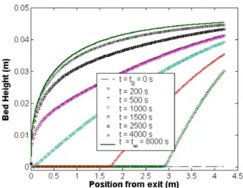
Fig. 3. Dynamic simulation: transient response for the filling phase of the kiln.
and anyway the mass flow rate will be less than one particle per second, which is the physical limit for granular matter. TheFig. 3shows an example of a filling phase simulation. The blue line represents the initial steady state profile, i.e. the kiln is “empty”. The dynamic simulation starts when the feeder volumetric flow rate is increased: the bed depth profile evolution can be seen for different times (200, 500, 1000, 1500 , 2500, 4000 and 8000 s). The bed depth pro-file converges on a new steady-state propro-file at 8000 s. This last profile can be also simulated with the Saeman’s equa-tion, the final value of flow rate being used. The dynamic model can also simulate one or several transitions occurred by a change in an operating parameter. For example,Fig. 4
presents the dynamic evolution of the bed depth profile after a change in the rotational speed. The initial bed depth pro-file is represented by the blue line. The dynamic simulation starts when the rotational speed is increased by a factor of two: the bed depth profile evolution can be seen for
differ-Fig. 4. Dynamic simulation: transient response of the exit flow rate to a step change in the rotational speed.
ent times (1600, 3200, 48,000, 6400 and 8000 s). The bed depth profile computed by the dynamic model converges on the profile computed by the steady state model with the final value of rotational speed.
3.2. Steady state results
The volumetric filling ratio, X, can be evaluated from
Eq. (2)in the steady state: the angle subtended by the bed at the cylinder axis, α(z), is computed from the local height
H(z), and the volumetric filling ratio is obtained by
numer-ical integration: α(z)= 2 cos−1 ! 1−H(z) R " X= 1 L $ z=L z=0 Vsolid(z) Vcyl(z) dz = 1 L $ z=L z=0 R2(α(z)− sin(α(z)))/2 πR2 dz = 2πL1 $ z=L z=0 (α(z)− sin(α(z)))dz (6)
The experimental and theoretical volumetric filling ratios are given inFig. 5for 12 experiments.
The bed was in slipping mode for all experiments with-out the grid inside the kiln because of the smoothness of the inside wall. So, the angle of repose of the bed mate-rial have been replaced by the wall friction angle in the
Eq. (1). However in spite of this modification, the predic-tive ability of the Seaman equation is good: the predicted volumetric filling ratios are very close to the experimental ones (results for cases 1–8). When the grid is rolled in-side the kiln, the rolling regime was observed and the com-parison between experimental and simulation results stays good.
It has been noted that the filling ratios obtained with the grid are generally larger than without; for example, the vol-umetric filling ratio values can be compared between the cases 2 and 10 because the experimental conditions are close.
3.3. Dynamic results: filling phase of the kiln
In course of the twelve previous experiments, the exit flow rate has been recorded during the filling of the kiln until the steady state regime was achieved. The transient volumetric flow rate along the kiln, and more particularly the exit flow rate, can be evaluated from the bed height profiles obtained by the integration of Eq. (4). In Figs. 6 and 7, the experimental exit flow rates without (Fig. 6) and with the grid (Fig. 7) for several different rotation speeds are compared with the theoretical ones. The inclination of kiln is fixed at 1◦.
The values of the delay, i.e. the necessary time for the first solid particles flow out of the kiln are always well
eval-Case Inlet flow rate kg.h-1 Rotation speed Rev.min-1 kiln inclination deg. Grid X exp % X theo % angle β (used in Eq. 1) deg. 1 15 1.7 1 No 11 13 21 2 23 2.9 1 No 11 12 21 3 26 4.0 1 No 10 10 21 4 35 5.2 1 No 11 10 21 5 21 1.7 2 No 11 12 21 6 34 2.9 2 No 11 11 21 7 47 4.0 2 No 10 10 21 8 62 5.2 2 No 10 11 21 9 9 1.7 1 Yes 12 12 33 10 20 2.9 1 Yes 15 16 33 11 41 4.0 1 Yes 24 23 33 12 51 5.2 1 Yes 24 24 33
Fig. 5. Experimental and theoretical volumetric filling ratio.
uated. The model gives rather good results for the simula-tion of the subsequent transient phase; however, a slightly tendency to overestimates the length of the transition phase for the cases without grid can be observed. These overesti-mations can be perhaps explained from some visual obser-vations: for the slipping regime (cases without grid), some small oscillations of the angle of repose have been observed in course of the experiments. Mellmann called this type of motion “surging”, which is characterised by periodic alter-nations between adhesive and kinetic friction of the bed on
Fig. 6. Experimental (markers) and simulated (lines) exit flow rates for a filling phase. Experiments without grid inside the kiln.
the wall[9]. An assumption of the model is to have a con-stant angle of repose.
3.4. Dynamic results: transient response to a step in operating parameters
In order to evaluate the quality of the developed model, new experiments have been carried out. These experiments consisted in fixing operating parameters (inclination angle, rotation speed, inlet flow rate), waiting for the steady state
Fig. 7. Experimental (markers) and simulated (lines) exit flow rates for a filling phase. Experiments with a grid inside the kiln.
Fig. 8. Transient responses of the exit flow rate for a positive and negative step in the rotation speed: experimental (markers) and simulated (lines) flow rates. Experiments without grid.
regime and applying a step (positive or negative) in one of the operating parameters. The response of the exit flow rate have been recorded until the new steady state was achieved. In this paper, the experimental and theoretical flow rates are compared only in the case of a positive and negative step in the rotation speed of the kiln (Figs. 8 and 9). These figures present respectively results without and with the grid.
In all presented cases, a large step is initially observed. The exit flow rate is instantaneously modified from its ini-tial value (the iniini-tial value of the flow rate is equal to the final value) as soon as the step is applied. Next, the flow rate returns slowly to its nominal value, i.e. value of the inlet flow rate. The magnitude and length of the transient phase are very well evaluated by the model in the two fig-ures. However, a difference between experimental and
the-Fig. 9. Transient responses of the exit flow rate for a positive and negative step in the rotation speed: experimental (markers) and simulated (lines) flow rates. Experiments with a grid.
oretical curves can be observed at the start of the positive steps.
4. Conclusion
The developed model for the simulation of the dynamic flow rate in a rotary kiln has been validated for varied exper-imental conditions: filling phases, transient responses after a step in the rotation speed or in the feed rate (not presented here). It is shown that this dynamic model, based on the Sae-man equation developed for rolling mode, works with the slipping mode too: the replacement of the angle of repose by the wall friction angle is sufficient.
From an industrial point of view, this model is able to predict and study the influence of the operating parameters on the filling ratios or the residence times for example. The model can be used for the design (steady state) and the control (transient phase) of rotating kilns.
The future steps of the project will be to adapt the model to the flow of reacting granular solids and to incorporate this model in a global model with thermal and chemical parts.
Appendix A. Details for the development of the dynamic equation
For one reason of simplicity, the indexes relative to the time (t) or to the axis of the kiln (z) have been omitted.
The mass conservation equation is written for the transi-tory regime and for a non reactive solid:
∂Ss ∂t = ∂Qv ∂z = ∂(SsUs) ∂z = Ss ∂Ss ∂z + Us ∂Us ∂z (A.1) where Ss and Us are, respectively, the cross-sectional area
of bed and the mean axial velocity: Ss = R2 2 (α− sin(α)) (A.2) Us= Qv Ss = 8 3πnR %tan(θ) sin(β)+ cot(β) R 2sin &α 2 '∂α ∂z ( × sin 3(α/2) α− sin(α) (A.3) The mean axial velocity is directly given by the Saeman’s equation.
If all the terms ofEq. (A.1)are replaced by theEqs. (A.2) and (A.3)and by their derivatives respective to the time and to the space, the new equation is:
(1− cos(α))∂α∂t =∂z∂ !4
3πnR
2cot(β) sin4&α 2
'∂α ∂z "
+2πnR tan(θ)sin(β) sin&α 2 '
sin(α)∂α ∂z (A.4)
The relations between α (angle subtended by the bed at the cylinder axis) and h (height of bed) are:
H = R&1− cos&α2'' (A.5)
sin&α 2 ' = !2H R − H2 R2 "1/2 (A.6)
cos(α)= 1 − 2 sin2&α2'= 1 − 2 !2H R − H2 R2 " (A.7) cos2&α 2 ' = 1 − sin2&α 2 ' = 1 −2H R + H2 R2 (A.8)
sin(α)= 2 sin&α 2 ' cos&α 2 ' = 2 !2H R − H2 R2 "1/2 × ! 1−2HR +H 2 R2 "1/2 (A.9) ∂α ∂z = 2 Rsin(α/2) ∂H ∂z (A.10) ∂α ∂t = 2 Rsin(α/2) ∂H ∂t (A.11)
With theEqs. (A.5)–(A.11), the partial derivative equation with αEq. (A.4)gives partial derivative equation with the variable H: !2H R − H2 R2 "1/2∂H ∂t = ∂ ∂z ) 2 3πnR 2cot(β)!2H R − H2 R2 "3/2 ∂H ∂z * + ) 2πnR tan (θ) sin (β) !2H R − H2 R2 "1/2 × ! 1−2H R + H2 R2 "1/2*∂H ∂z (A.12) The finalEq. (A.13)can be written:
FH1/2∂H ∂t − UTtan(θ) sin(β) F 1/2 H (1− FH)1/2 ∂H ∂z = ∂z∂ ! U3TRcot(β)FH3/2∂H ∂z " with FH = 2HR −H 2 R2 and UT= 2πnR (A.13) Appendix B. Nomenclature H bed height (m) L length of kiln (m) n rotational speed, rpm (tr s-1)
Qv volumetric flow rate (m3s−1)
R kiln radius, m
Ss cross-sectional area of bed (m2)
t time (s)
Us mean axial velocity (m s−1)
Vcyl volume of kiln (m3)
Vsolid volume of solid bed (m3)
Xexp experimental volumetric filling ratio
Xtheo theoretical volumetric filling ratio
z axial distance from the cylinder discharge end (m)
Greek letters
α angle subtended by the bed at the cylinder axis, β angle of repose of the granular solid,
θ angle between the kiln and the horizontal,
References
[1] W. C Saeman, Passage of solids trough rotary kilns: factors affecting time of passage, Chem. Eng. Prog. 47 (1951) 508–514.
[2] J. Mu, D.D. Perlmutter, The mixing of granular solids in a rotary cylinder, A.I.Ch.E. J. 26 (1980) 928–934.
[3] P.S.T. Sai, G.D. Surender, A.D. Damodaran, V. Suresh, Z.G. Philip, K. Sankaran, Residence time distribution and material flow studies in a rotary kiln, Metall. Trans. B 21B (1990) 1005–1011.
[4] S. Das gupta, S.K. Bhatia, D.V. Khakhar, Axial transport of granular solids in horizontal rotating cylinders. Part 1. Theory, Powder Tech. 67 (1991) 145–151.
[5] J. Perron, R.T. Bui, Rotary cylinders: solid transport prediction by dimensional and rheological analysis, Can. J. Chem. Eng. 68 (1990) 61–68.
[6] D.V. Khakhar, J.J. Mc Carthy, T. Shinbrot, J. Ottino, Transverse flow and mixing of granular materials in a rotating cylinder, Phys. Fluids 9 (1997) 31–43.
[7] R.J. Spurling, J.F. Davidson, D.M. Scott, The transient response of granular flows in an inclined rotating cylinder, Trans. I. Chem. E. 79 (2001) 51–61.
[8] P.S.T. Sai, A.D. Damodaran, G.D. Surender, Prediction of axial ve-locity profiles and solids hold-up in a rotary kiln, Can. J. Chem. Eng. 70 (1992) 438–443.
[9] J. Mellmann, The transverse motion of solids in rotating cylinders—forms of motion and transition behavior, Powder Technol. 118 (2001) 251–270.

![Fig. 2. Schemes of the rotary kiln with the main variables used in the equations. Saeman [1]: Q v (z) = 4 3 πnR 3 ! tan(θ) sin(β) + cot(β) dH(z)dz " × ! 2H(z) R − H(z) 2R2 " 3/2 (1) This equation gives the local volumetric solid flow rate (Q v ) ac](https://thumb-eu.123doks.com/thumbv2/123doknet/12132011.310234/4.892.157.731.145.388/schemes-rotary-variables-equations-saeman-equation-gives-volumetric.webp)