HAL Id: hal-01079027
https://hal.archives-ouvertes.fr/hal-01079027
Submitted on 31 Oct 2014
HAL is a multi-disciplinary open access
archive for the deposit and dissemination of
sci-entific research documents, whether they are
pub-lished or not. The documents may come from
L’archive ouverte pluridisciplinaire HAL, est
destinée au dépôt et à la diffusion de documents
scientifiques de niveau recherche, publiés ou non,
émanant des établissements d’enseignement et de
Kerr nonlinearity mitigation in 5 x 28-GBd PDM
16-QAM signal transmission over a
dispersion-uncompensated link with backward-pumped
distributed Raman amplification
Isaac Sackey, Francesco da Ros, Mahmoud Jazayerifar, Thomas Richter,
Christian Meuer, Markus Nölle, Lutz Molle, Christophe Peucheret, Klaus
Petermann, Colja Schubert
To cite this version:
Isaac Sackey, Francesco da Ros, Mahmoud Jazayerifar, Thomas Richter, Christian Meuer, et al..
Kerr nonlinearity mitigation in 5 x 28-GBd PDM 16-QAM signal transmission over a
dispersion-uncompensated link with backward-pumped distributed Raman amplification. Optics Express, Optical
Society of America - OSA Publishing, 2014, 22 (22), pp.27381-27391. �10.1364/OE.22.027381�.
�hal-01079027�
Kerr nonlinearity mitigation in 5 × 28-GBd PDM
16-QAM signal transmission over a
dispersion-uncompensated link with backward-pumped
distributed Raman amplification
Isaac Sackey,1,2,* Francesco Da Ros,2,3 Mahmoud Jazayerifar,1 Thomas Richter,2 Christian Meuer,1,2 Markus Nölle,2 Lutz Molle,2 Christophe Peucheret,4
Klaus Petermann,1 and Colja Schubert2
1Technische Universität Berlin, Einsteinufer 25, D-10587 Berlin, Germany
2Fraunhofer Institute for Telecommunications Heinrich Hertz Institute, Einsteinufer 37, D-10587 Berlin, Germany 3Department of Photonics Engineering, Technical University of Denmark, DK-2800 Kgs. Lyngby, Denmark
4FOTON Laboratory, CNRS UMR 6082, ENSSAT, University of Rennes 1, F-22305 Lannion, France *isaac.sackey@hhi-extern.fraunhofer.de
Abstract: We present experimental and numerical investigations of Kerr
nonlinearity compensation in a 400-km standard single-mode fiber link with distributed Raman amplification with backward pumping. A dual-pump polarization-independent fiber-based optical parametric amplifier is used for mid-link spectral inversion of 5 × 28-GBd polarization-multiplexed 16-QAM signals. Signal quality factor (Q-factor) improvements of 1.1 dB and 0.8 dB were obtained in the cases of a single-channel and a five-channel wavelength-division multiplexing (WDM) system, respectively. The experimental results are compared to numerical simulations with good agreement. It is also shown with simulations that a maximum transmission reach of 2400 km enabled by the optical phase conjugator is possible for the WDM signal.
©2014 Optical Society of America
OCIS codes: (060.2330) Fiber optics communications; (060.1660) Coherent communications;
(060.4230) Multiplexing.
References and links
1. A. D. Ellis, J. Zhao, and D. Cotter, “Approaching the non-linear Shannon limit,” J. Lightwave Technol. 28(4), 423–433 (2010).
2. V. Mikhailov, R. I. Killey, J. Prat, and P. Bayvel, “Limitation to WDM transmission distance due to cross-phase modulation induced spectral broadening in dispersion compensated standard fiber systems,” IEEE Photon. Technol. Lett. 11(8), 994–996 (1999).
3. M. Morshed, A. J. Lowery, and L. B. Du, “Improving performance of optical phase conjugation by splitting the nonlinear element,” Opt. Express 21(4), 4567–4577 (2013).
4. C. Behrens, R. I. Killey, S. J. Savory, M. Chen, and P. Bayvel, “Nonlinear transmission performance of higher-order modulation formats,” IEEE Photon. Technol. Lett. 23(6), 377–379 (2011).
5. L. Molle, M. Seimetz, D.-D. Gross, R. Freund, and M. Rohde, “Polarization multiplexed 20 Gbaud square 16-QAM long-haul transmission over 1120 km using EDFA amplification,” Proc. European Conference on Optical Communication, (ECOC), 8.4.4 (2009).
6. X. Chen, X. Liu, S. Chandrasekhar, B. Zhu, and R. W. Tkach, “Experimental demonstration of fiber nonlinearity mitigation using digital phase conjugation,” Proc. Optical Fiber Communication. Conference (OFC), OTh3c.1, (2012).
7. D. Rafique and A. D. Ellis, “Nonlinearity compensation in multi-rate 28 Gbaud WDM systems employing optical and digital techniques under diverse link configurations,” Opt. Express 19(18), 16919–16926 (2011). 8. E. Ip, “Nonlinearity compensation using backpropagation for polarization-multiplexed transmission,” J.
Lightwave Technol. 28(6), 939–951 (2010).
9. E. Mateo, M.-F. Huang, F. Yaman, T. Wang, Y. Aono, and T. Tajima, “Nonlinearity compensation using very low complexity backward propagation in dispersion managed links,” Proc. Optical Fiber Communication. Conference (OFC), OTh3C.4, (2012).
10. S. L. Jansen, D. van den Borne, P. M. Krummerich, S. Spälter, G. D. Khoe, and H. de Waardt, “Long-haul DWDM transmission systems employing optical phase conjugation,” IEEE J. Sel. Top. Quantum Electron. 12(4), 505–520 (2006).
11. F. Da Ros, I. Sackey, R. Elschner, T. Richter, C. Meuer, M. Nölle, M. Jazayerifar, K. Petermann, C. Peucheret, and C. Schubert, “Kerr nonlinearity compensation in a 5x28-GBd PDM 16-QAM WDM system using fiber-based optical phase conjugation,” Proc. European Conference on Optical Communication, ECOC, P.5.3, (2014). 12. M. Pelusi, “All-optical compensation of fiber nonlinearity by phase conjugation,” in Proceedings of the
OptoElectronics and Communications Conference. OECC, WS4–7, (2013).
13. P. Frascella, C. Antony, S. J. Fabbri, F. C. G. Gunning, P. Gunning, W. McAuliffe, D. Cassidy, and A. D. Ellis, “Impact of Raman amplification on a 2-Tb/s coherent WDM system,” IEEE Photon. Technol. Lett. 23(14), 959– 961 (2011).
14. S. L. I. Olsson, T. A. Eriksson, C. Lundström, M. Karlsson, and P. A. Andrekson, “Linear and nonlinear transmission of 16-QAM Over 105 km phase-sensitive amplified link,” Proc. Optical Fiber Communication. Conference (OFC), OTh1h.3, (2014).
15. M. F. C. Stephens, M. Tan, I. D. Phillips, S. Sygletos, P. Harper, and N. J. Doran, “1.14 Tb/s DP-QPSK WDM polarization-diverse optical phase conjugation,” Opt. Express 22(10), 11840–11848 (2014).
16. I. Sackey, F. Da Ros, T. Richter, R. Elschner, M. Jazayerifar, C. Meuer, C. Peucheret, K. Petermann, and C. Schubert, “Design and performance evaluation of an OPC device using a dual-pump polarization-independent FOPA,” Proc. European Conference on Optical Communication, ECOC, Tu.1.4.4, (2014).
17. H. Hu, R. M. Jopson, A. H. Gnauck, M. Dinu, S. Chandrasekhar, X. Liu, C. Xie, M. Montoliu, S. Randel, and C. J. McKinstrie, “Parametric amplification and wavelength conversion of a 2.048-Tb/s WDM PDM 16-QAM signal,” Proc. European Conference on Optical Communication, ECOC, We.2.5.2, (2014).
18. I. D. Philips, M. Tan, M. F. C. Stephens, M. E. McCarthy, E. Giacoumidis, S. Sygletos, P. Rosa, S. Fabbri, S. Randel, S. T. Le, T. Kanesan, S. K. Turitsyn, N. J. Doran, P. Harper, and A. D. Ellis, “Exceeding the nonlinear-Shannon limit using Raman laser based amplification and optical phase conjugation,” Proc. Optical Fiber Communication. Conference (OFC), M3C.1, (2014).
19. H. Hu, R. M. Jopson, A. H. Gnauck, M. Dinu, S. Chandrasekhar, X. Liu, C. Xie, M. Montoliu, S. Randel, and C. J. McKinstrie, “Fiber nonlinearity compensation of an 8-channel WDM PDM-QPSK signal using multiple phase conjugations,” Proc. Optical Fiber Communication. Conference (OFC), OTh3c.1, (2014).
20. K. Solis-Trapala, T. Inoue, and S. Namiki, “Signal power asymmetry tolerance of an optical phase conjugation-based nonlinear compensation system,” Proc. European Conference on Optical Communication, ECOC, We.2.5.4, (2014).
21. X. Liu, S. Chandrasekhar, P. J. Winzer, R. W. Tkach, and A. R. Chraplyvy, “Fiber-nonlinearity-tolerant superchannel transmission via nonlinear noise squeezing and generalized phase-conjugated twin waves,” J. Lightwave Technol. 32(4), 766–775 (2014).
22. Y. Tian, Y.-K. Huang, S. Zhang, P. R. Prucnal, and T. Wang, “Demonstration of digital phase-sensitive boosting to extend signal reach for long-haul WDM systems using optical phase-conjugated copy,” Opt. Express 21(4), 5099–5106 (2013).
23. S. K. Ibrahim, J. Zhao, F. C. G. Gunning, P. Frascella, F. H. Peters, and A. D. Ellis, “Towards a practical implementation of coherent WDM: analytical, numerical, and experimental studies,” IEEE Photon. J. 2(5), 833– 847 (2010).
24. T. Richter, R. Elschner, A. Gandhe, K. Petermann, and C. Schubert, “Parametric amplification and wavelength conversion of single- and dual-polarization DQPSK signals,” IEEE J. Sel. Top. Quantum Electron. 18(2), 988– 995 (2012).
25. D. Marcuse, C. R. Manyuk, and P. K. A. Wai, “Application of the Manakov-PMD equation to studies of signal propagation in optical fibers with randomly varying birefringence,” J. Lightwave Technol. 15(9), 1735–1746 (1997).
26. M. N. Islam, “Raman amplifiers for telecommunications,” IEEE J. Sel. Top. Quantum Electron. 8(3), 548–559 (2002).
27. J. Bromage, “Raman amplification for fiber communication systems,” J. Lightwave Technol. 22(1), 79–93 (2004).
28. M. Islam, “Statistics of polarization dependent gain in Raman fiber amplifiers due to PMD,” Proc. Conference on Lasers and Electro-Optics (CLEO), CTuJ, (2001).
1. Introduction
The quest for increasing transmission reach in long haul optical links demands a sufficiently high optical signal-to-noise ratio (OSNR) to be guaranteed at the receiver, and one way to achieve such OSNR is by injecting high signal launch powers into the spans of the optical link. Nevertheless, Kerr nonlinearity, in the form of self-phase modulation (SPM), inter- and intra-channel cross-phase modulation (XPM), and inter-and intra-channel four-wave mixing (FWM), provide an upper bound to the maximum transmittable signal launch power per span, thus reducing the reach for error free transmission [1,2]. In addition, transmission at low
launch powers per span is limited by repeater noise such as amplified spontaneous emission (ASE) noise from erbium-doped fiber amplifiers (EDFAs). The degrading impact of fiber nonlinearities on systems with tightly packed channels, e.g. dense wavelength-division multiplexed (DWDM) systems, with higher-order modulation can be very significant [3–5].
In order to mitigate the signal transmission impairments due to Kerr nonlinearity, various techniques involving electronic domain compensation [6–9] as well as optical domain compensation [10–20] have been investigated. It has been shown in [10,13] that systems with bi-directional distributed Raman amplification (DRA) have power-dispersion maps which make them much more suitable for fiber nonlinearity mitigation through optical phase conjugation (OPC) than pure EDFA amplified links. A recent fiber nonlinearity mitigation study implemented electrical domain digital phase conjugation (DPC) technique [6]. In this scheme, the transmitted optical signal is conjugated in the digital domain after the first half of the link. The conjugated signal is converted back into the optical domain and it is transmitted over the remaining half of the link. This study also employed distributed Raman amplification with backward pumping but was focused on a single-channel 10-GBd 16-quadrature amplitude modulation (QAM) signal. In a similar work applied to the nonlinear compensation of a polarization-division multiplexed (PDM) quadrature phase shift keying (QPSK) signal, the signal and its inverted spectrum (a conjugate of the signal also known as idler) were generated at the transmitter and both waves were transmitted through the link to the receiver. The twin waves (signal and idler) were detected at the receiver and the idler was again conjugated before its field was coherently superimposed to the field of the signal via digital signal processing (DSP) to cancel out the nonlinear distortions accumulated on the signal [21, 22]. However, the DSP power requirements in a high speed data link dominated by fiber impairments can be significantly high. Therefore optical domain nonlinearity compensation has attracted the attention of researchers. All-optical coherent superposition of the signal and idler after the link in a low noise phase sensitive amplifier (PSA) has been shown to exhibit a trend to cancel out the effect of fiber nonlinearities [14]. This investigation was carried out for a single-channel 10-GBd single-polarization 16-QAM signal.
Mid-link spectral inversion is a well-known technique for fiber nonlinearity and chromatic dispersion compensation. The scheme involves the conjugation of the electric field of the propagating signal in the middle of the entire transmission link using an OPC device. The conjugated signal is then transmitted for the remaining half of the link. Consequently, the nonlinear distortions that have been accumulated in the first half of the link are compensated for in the second half of the link [10–12]. Recent studies on design and performance evaluation of OPC devices based on non-degenerate FWM have been performed in a 100-GHz spaced 10 × 114-Gb/s PDM QPSK system [15]. In addition, WDM systems with up to 8-channels using PDM 16-QAM signals have been used to characterize an OPC device that employs a non-degenerate FWM process [16,17].
The combination of Raman-based amplification and OPC scheme has been recently demonstrated for nonlinear distortions compensation. In [18], the combined technique was implemented in a 7 × 114-Gb/s dual-polarization QPSK system with 100 GHz spacing whereas in [19] a 50-GHz spaced 8 × 32-GBd PDM QPSK system was used. Furthermore, a polarization-dependent OPC device was implemented in a 25-GHz spaced 4 × 12-GBd single-polarization 16-QAM system for the compensation of nonlinear distortions in [20]. All these demonstrations employed OPC device based on non-degenerate FWM process.
We have recently demonstrated Kerr nonlinearity compensation in a five-channel 28-GBd PDM 16-QAM signals with 50-GHz channel spacing using a non-degenerate dual-pump polarization-independent fiber-based optical parametric amplifier (FOPA) as OPC device [11]. An improvement of the signal quality factor, (Q-factor derived from the BER of each launch power) by 0.9 dB allowed an extension of the reach to 800 km in the investigated dispersion managed link, whereas the Q factor was found to be below the hard-decision
forward error correction (HD-FEC) threshold without the fiber nonlinearity compensation scheme.
In this paper, we extend our recent experimental investigation on Kerr nonlinearity compensation using mid-link spectral inversion by further experimental and numerical studies for a dispersion-unmanaged link made of standard single-mode fiber (SSMF). The particular link is composed of 4 × 100-km SSMF spans employing distributed Raman amplification with backward pumping. The transmitter and receiver configuration are the same as in [11]. The design and characterization of the employed dual-pump polarization-independent FOPA used as OPC device has already been reported in detail in [16]. In addition, the experimental results are compared with numerical simulations using VPItransmissionMaker v8.7. The numerical model is used to forecast the possible transmission reach extension.
The organization of the paper is as follows: In section 2, we describe the system experimental setup. A numerical modeling is presented in section 3, which is fitted to the experimental results in section 4, which also highlights discussions on the key results. A forecast for the Q-factor after 2800 km transmission is shown using our numerical model. Finally, concluding remarks are given in section 5.
2. Experimental setup
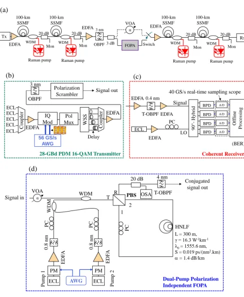
Figure 1 shows the experimental setup, consisting of a 28-GBd PDM 16-QAM transmitter, two 100-km SSMF spans forming the first half of the link, the FOPA (OPC device), another two 100-km SSMF spans forming the second half of the link, and a digital coherent receiver. Five external cavity lasers (ECLs) at 1549.32 nm, 1549.72 nm, 1550.12 nm, 1550.52 nm and 1550.92 nm (50-GHz channel spacing) served as continuous wave (cw) WDM signal sources. The channels were combined with an optical coupler, amplified by an EDFA before the signal was modulated with an IQ modulator (IQ Mod). The IQ Mod was driven by a two-channel 56-GS/s arbitrary waveform generator (AWG), which provided the in-phase and quadrature components of the single-polarization 28-GBd 16-QAM signal. After using a polarization multiplexing emulator (PolMux) to generate a PDM signal, the WDM channels were separated using a wavelength selective switch (WSS). The channels were individually decorrelated by delaying the symbols of neighboring channels by a minimum of 100 symbols using various lengths of SSMF patch cords in the five individual optical paths [23]. After combining all five WDM channels with an optical coupler, the 28-GBd PDM 16-QAM signals were amplified with an EDFA and the out-of-band ASE noise was suppressed with a 3-nm optical band pass filter (OBPF). The state-of-polarization (SOP) of the data was varied on the Poincaré sphere using a polarization scrambler. The entire transmission link consists of 400-km SSMF, and it is divided into four spans, and four Raman pumps (one for each span). After the transmitter, the signal was launched into an EDFA that enabled changing the launch power into the first span. The Raman pumps were used in the backward distributed pumping scheme, via WDM couplers, to achieve a symmetric power profile per span. After 200 km of transmission, an EDFA was set to a constant output power of 17 dBm so as to keep the input signal power into the FOPA constant. After suppressing the ASE noise from the EDFAs using a 3-nm OBPF, a 3-dB coupler was used to split the signal into two parts with one part going through the OPC device (dual-pump polarization-independent FOPA) whereas the other portion bypassed the OPC device.
(b) Signal out (c) PC 0.4 nm Delay EDFA ECL OBPF EDFA WS S 28-GBd PDM 16-QAM Transmitter 56 GS/s AWG 3 nm Pol Mux IQ Mod T-OBPF (BER) EDFA
40 GS/s real-time sampling scope
EDFA LO 90 °-H y b ri d O ffl in e Pro ces si n g A/D A/D Coherent Receiver ECL A/D A/D BPD BPD BPD BPD EDFA Signal C o u p ler ECL ECL ECL ECL C o u p ler 20 dB EDFA (a) 3 dB WDM WDM EDFA Mon 20 dB Raman pump 100-km SSMF WDM Switch FOPA EDFA Tx 100-km SSMF Raman pump Mon Mon 20 dB Raman pump 100-km SSMF WDM 100-km SSMF Raman pump Mon 20 dB Rx α VOA OBPF 3 nm Polarization Scrambler (d) Signal in Conjugated signal out T-OBPF PC PC PC L = 300 m, γ = 16.3 W-1km-1 λ0= 1555.6 nm, S = 0.019 ps/(nm2.km) = 1.4 dB/km 0 .8 n m 4 nm 20 dB P u m p 1 WDM Dual-Pump Polarization Independent FOPA HNLF 1 2 T R PBS 0 .8 n m ECL PM AWG E DF A P u m p 2 ECL PM E DF A OSA WDM α VOA
Fig. 1. Experimental setup showing the: (a) 400 km SSMF transmission link with backward-pumped distributed Raman amplification (Tx: transmitter, Rx: receiver), (b) Tx: 28-GBd PDM 16-QAM transmitter, (c) Rx: coherent receiver, (d) dual-pump polarization-independent FOPA used as OPC device.
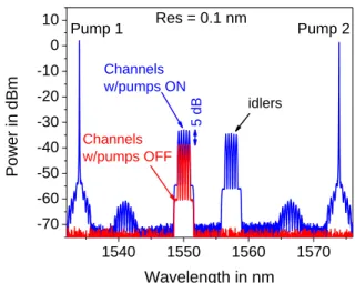
In order for the OPC device to be suitable for real-life WDM applications, a flat gain-bandwidth of the OPC device is desirable. A dual-pump polarization-independent FOPA fulfills this requirement [24]. In addition, a dual-pump FOPA allows the provision of counter-phasing mechanism which enables the suppression of pump phase modulation tones transferred from the pumps to the generated idler(s) in the OPC device [16,24]. Note that pump phase modulation is required to increase the stimulated Brillouin scattering threshold of the highly-nonlinear fiber used in the OPC device. Moreover, as a result of the implemented counter-phasing technique, the phase-matching condition among the interacting waves was not distorted by the pump phase modulation. The design and performance evaluation of the OPC device that was used in this experiment is explained in details in [16]. The conjugated signal conversion efficiency used in this experiment was 4 dB with a 5-dB on-off gain for the signal, as shown in Fig. 2.
1540 1550 1560 1570 -70 -60 -50 -40 -30 -20 -10 0 10 idlers 5 dB Channels w/pumps ON Channels w/pumps OFF Pump 2 Pump 1 Res = 0.1 nm Power in dBm Wavelength in nm
Fig. 2. A 5-channel OPC output spectrum showing 5-dB signal on-off gain and 4-dB conjugated signal conversion efficiency measured after a 20-dB monitor coupler.
In order to obtain the same accumulated noise into the second half of the transmission link, a variable optical attenuator (VOA) was used to ensure that the input powers (for the cases with and without OPC) into the EDFA at the beginning of the second half of the link were the same. An optical switch was used to either select the output of the OPC device (conjugated signal) or the signal which bypasses the OPC device before launching the selected data into the remaining 200-km SSMF link.
The coherent receiver consists of a local oscillator (100-kHz linewidth) whose signal was combined with the received data signal in a 90° optical hybrid. Four balanced photo detectors (BPD) were connected to the hybrid outputs, and a real-time sampling scope (40-GS/s sampling rate, 20-GHz 3-dB bandwidth) was used as analog-to-digital converter (A/D). Offline processing was performed on a desktop computer including resampling, front-end correction, electronic dispersion compensation in the frequency domain, frequency-offset compensation, blind adaptive time-domain equalization using a constant-modulus and multi-modulus algorithm, carrier-phase estimation by blind phase search, de-mapping and error counting.
3. Numerical modeling
A numerical model has been implemented using VPItransmissionMaker v8.7. The model is developed such that it fits to the experimental results. In order to do so, the back-to-back performance of the model is first fitted to the back-to-back performance of the experimental setup. The OSNR at the transmitter output was experimentally measured to be 34.5 dB. In the model, additive Gaussian noise was added to the output of an ideal transmitter such that the same OSNR was achieved at the transmitter output. Shot noise and thermal noise at the receiver are taken into account, and then the BER vs. OSNR plots of the model and the experiment are fitted. Two independent pseudo-random binary sequences (PRBSs) are used to generate the data bits of the PDM signal in the two polarizations. Five WDM channels are considered, as explained in the description of the experimental setup. The modulation format, bitrate, and other specifications are the same as in the experimental setup. There is no digital signal processing in the receiver, and the electrical filter which is used at the receiver is a 4th order Bessel filter. Third-order Gaussian OBPFs are used to separate the WDM channels.
The optical propagation of the two polarizations in the SSMF is modeled by simulating the Manakov polarization mode dispersion (PMD) equation through the split step Fourier method (SSFM) [25]. The FOPA is modeled as an ideal phase conjugator which does not cause any penalty. This is a fair assumption since the FOPA that is used in the experiment has a low
gain resulting in a low penalty, which is negligible compared to the penalty caused by the transmission fibers [16]. The Kerr induced nonlinear distortion of the transmission fibers is taken into account. The simulated SSMF has a dispersion of 16 ps/nm/km, a dispersion slope of 0.08 ps/nm2km, a PMD coefficient of 0.1 ps/km, a nonlinear coefficient of 1.3 /W/km, and a loss of 0.2 dB/km. Compared to a link with a discrete amplifier, a link with a backward-pumped distributed Raman amplifier has a higher minimum signal power. Therefore, the link with distributed Raman amplification has a better noise performance than a link with discrete amplification [26]. A parameter, namely the effective noise figure (NFeff), is defined in [27] and by employing the concept of determining the NFeff as described in [28], the NFeff of our simulated link with backward-pumped DRA is found to be -3.1 dB.
The effects of Raman amplified spontaneous emission, double Rayleigh back-scattering (DRB), noise transfer of pump to signal, cross gain modulation of the Raman gain, and polarization dependent gain (PDG) of the Raman amplifier are all taken into account in the numerical model. Specifically, the pump-to-signal noise transfer was considered negligible in the backward pumping scenario [27]. In addition, the PDG of DRA is also very small [28] and in our simulations it is less than 0.4 dB. We have also considered a temperature of 300 Kelvins for the spontaneous Raman scattering, which is the dominant noise source according to our simulations. We have used a pump power of 26 dBm in our simulations, which enables to compensate for the loss of a 100-km fiber span when used as a backward propagating Raman pump from the end of the span.
4. Results and discussions
We firstly measured the bit-error ratio (BER) performance for a single-channel scenario. Four channels were suppressed at the output of the WSS and only the center channel (at 1550.12 nm) was allowed to propagate along the transmission link and it was then detected at the receiver. The launch power per polarization into the first span of the polarization-scrambled signal was adjusted from 12 dBm to + 6 dBm by tuning the gain of the EDFA located at the transmitter output. In order to obtain approximately the same power at the end of the span as at its input (referred to as launch power under test), the power of the Raman pump was adjusted (whilst monitoring the power at the output of the 20-dB tap coupler after the span) until the launch power into the second span was equal to the launch power under test (considering the low total insertion losses of the WDM coupler and of the 20-dB monitor coupler of about 0.6 dB). In a similar fashion, the output signal power of the second span was also set equal to the input signal power into the span by adjusting the output power of the Raman pump after that span. The launch power into the third span is set with the EDFA after the OPC. Note, however, that since the FOPA is operated in the low-gain regime to avoid signal degradation [18], an additional EDFA at the input of span 3 is required. The previous procedure is used in setting the launch power per span (following adjustment of the Raman pumps) for the remaining half of the link.
Figure 3 shows a plot of the Q-factor of the single channel (ch-3 alone) versus the launch power per polarization into the fiber spans. The filled blue () and red () symbols indicate the experimentally determined signal Q-factors with and without OPC over the 400-km SSMF link, respectively. Remark that the OPC provides automatic second order chromatic dispersion compensation after signal transmission over the link, thus the case without OPC requires chromatic dispersion compensation, which is achieved in the receiver DSP. It can be seen that, without the OPC implementation, a maximum Q-factor of 11.2 dB at a launch power of 5 dBm is obtained, whereas with the implementation of the OPC, the Q-factor is improved to 12.4 dB (above 1.1 dB improvement) at 3-dB increased optimum launch power. This also yields a considerable increase in the nonlinear threshold. The 28-GBd PDM 16-QAM constellations diagrams for the cases with and without OPC are also shown in Fig. 3.
All the five WDM channels were then allowed to propagate over the transmission link for the WDM experimental investigations. The signal launch power per channel per polarization
into the spans was adjusted from 11 dBm to + 4 dBm by using the same procedure as in the single-channel case. The center channel (ch-3) was investigated in the WDM scenario. It can be seen from Fig. 4 that, without the OPC operation, a maximum Q-factor of 11 dB at a launch power of 5 dBm is obtained, whereas with the implementation of the OPC, the Q-factor improved to 11.8 dB (0.8 dB improvement) at 2-dB increased optimum launch power. It is also clear that the nonlinear threshold is increased substantially with OPC operation. The simulation model was implemented in the WDM scenario and the corresponding results are represented with open blue () and red () symbols in Fig. 4. An excellent agreement between simulation and experimental results can be seen.
HD - FEC Threshold -12 -10 -8 -6 -4 -2 0 2 4 6 2 4 6 8 10 12
ch-3 alone: w/o OPC ch-3 alone: w/ OPC
Q-F
actor in
dB
Launch power /pol in dBm
X-POL Y-POL
Fig. 3. Plot of Q-factor as a function of launch power per polarization for the single channel scenario showing the experimental results for the cases with and without OPC with the corresponding experimental constellation diagrams at a launch power of + 2 dBm/pol.
HD-FEC Threshold -12 -10 -8 -6 -4 -2 0 2 4 6 2 4 6 8 10 12 Q-Fac tor in dB
Launch power /ch/pol in dBm
Exp. 5-chs: w/ OPC Sim. 5-chs: w/ OPC Exp. 5-chs: w/o OPC Sim. 5-chs: w/o OPC
X-POL Y-POL
Fig. 4. Plot of Q factor as a function of launch power/ch/pol for the WDM scenario showing both the experimental and numerical simulation results for the cases with and without OPC with the corresponding experimental constellation diagrams at a launch power of + 2 dBm/ch/pol. The center channel was used in the WDM investigations.
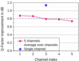
Figure 5 illustrates the Q-factor improvement at the optimal launch power without OPC (5 dBm/ch/pol) and with OPC (3 dBm/ch/pol) plotted for each WDM channel. It can be seen that all the channels have similar performances with an average Q-factor improvement of 0.8 dB. The blue star indicates the Q-factor improvement above 1.1 dB that was obtained in the single-channel scenario with only channel three.
1 2 3 4 5 0.0 0.2 0.4 0.6 0.8 1.0 1.2 5 channels
Average over channels Single channel Q-Factor improvement in dB Channel index
Fig. 5. Q factor improvement for the individual WDM channels, the blue star indicates the Q-factor improvement in the single-channel case, indicates the Q-Q-factor improvement in the single-channel case.
Using our numerical model, the Q-factor for the cases with and without OPC implementation has been calculated for longer transmission distances up to 2800 km for the five-channel WDM scenario, as shown in Fig. 6 (note that the WDM center channel was used in the performance evaluation.). In this figure, the maximum Q-factor is plotted versus the length of the transmission link. The link still has only one mid-link OPC and SSMF spans with 100-km length. The maximum Q-factor is obtained at the optimum powers (i.e. 3 dBm/ch/pol for the case with OPC and 5 dBm/ch/pol for case without OPC from Fig. 4) which stayed almost constant as the number of spans increased. It is observed that, without the OPC technique, the transmission reach is limited to a maximum of ~1300 km (i.e. at the HD-FEC threshold). However, by using OPC the transmission distance can be extended up to 2400 km. HD-FEC Threshold 0 500 1000 1500 2000 2500 3000 2 4 6 8 10 12 Numerical 5-chs: w/ OPC Numerical 5-chs: w/o OPC
Q-Factor in dB
Transmission reach in km
Fig. 6. Numerical simulations showing Q-factor versus reach of the link for the cases with and without OPC obtained at the optimum launch power levels.
It is seen that the Q-factor performance degrades as the transmission distances increase, even for the case with OPC implementation. The nonlinearity compensation of the OPC technique is degraded by effects such as PMD, fiber-length mismatch before and after OPC, non-symmetrical power distribution versus the fiber length, as observed in [18]. Additionally, the generation of an idler at a different wavelength results in a dispersion mismatch between
signal and idler, which further contribute to sub-optimum distortions compensation. However, in our experiment, the wavelength separation between the center channel signal and its corresponding idler was 7.2 nm (signal at 1550.12 nm, idler at 1557.32 nm) therefore leading to signal/idler dispersion mismatch of 0.39 ps/nm/km (note that the dispersion slope of SSMF at the zero-dispersion wavelength is ~0.087 ps/nm2/km). This dispersion mismatch is a small value and, according to our simulations, its impact is insignificant.
The number of WDM channels was increased from five-channels to eleven-channels using the simulation model and the system performance of the center channel was evaluated. Figure 7 shows the numerical results for the Q-factor performance as a function of the launch power per channel. Comparing these with the numerical results from the five-channel investigation in Fig. 4, it is observed that the Q-factors in the linear regime were not changing as the number of WDM channels was increased, as expected. The maximum achieved Q-factor at the optimum launch power decreases slightly with the increased number of WDM channels. It is decreased by 0.1 dB and 0.3 dB for the case without and with OPC, respectively. This is attributed to the fact that, as the number of WDM channels increases, larger nonlinear distortions occur, especially at higher launch powers. Thus the link with OPC has slight decrease in Q-factor since it has higher optimum launch power than the link without OPC. Nonetheless, Fig. 7 shows also that the maximum Q-factor of the link with OPC can be still improved by 0.7 dB in the case of 11-channels, which is only 0.2 dB less compared to the 5-channel case.
Figure 8 shows the numerical simulation results for the loss experienced by the signal over a 100-km SSMF span with backward-pumped DRA. Taking into consideration the input and output effective lengths, Leff (where the nonlinear effects are severe), it is observed that the signal power evolution versus length is not symmetrical over the effective lengths at both ends of the fiber span with respect to the middle of the span. The signal power decreases with a constant slope of 0.2 dB/km at the input of the span while it increases with a variable slope toward the end of the span due to the depletion of the backward propagating Raman pump along the fiber. The ideal case should have a symmetric power distribution over the fiber length with respect to the middle point of the fiber. This ideal power-length slope cannot be achieved by a single Raman pump for a 100-km fiber span.
HD-FEC Threshold -12 -10 -8 -6 -4 -2 0 2 4 4 6 8 10 12 Q-Factor in dB
Launch power /ch/pol in dBm Numerical 11-chs: w/ OPC Numerical 11-chs: w/o OPC
Fig. 7. Numerical simulation results showing Q-factor versus launch power per channel plot of an 11-channel WDM scenario for the cases with and without OPC over a 400-km SSMF link.
0 20 40 60 80 100 -14 -12 -10 -8 -6 -4 -2 0 Relative power in dB Length in km 70-km fiber span 100-km fiber span Leff
Fig. 8. Numerical simulation results showing the relative power distribution over the length for a 100-km and 70-km fiber spans. Both fibers are amplified with a backward-pumped DRA such that the output and input powers are the same.
The power evolution in a 70-km fiber span with backward-pumped DRA is also shown in Fig. 8. It can be seen that, in this case, the power evolution at the input and output of the 70-km span are more symmetric due to the lower amount of loss in the span (i.e. shorter length), leading to lower Raman pump power requirement at the output end of the span, hence a lower Raman gain, in order to make the span transparent. Therefore, it can be expected that the nonlinearity compensation for shorter links will be more efficient than that of longer links. Moreover, shorter links will result in lower maximum loss per span, which improves the noise performance and therefore is expected to lead to higher Q-factors. Using our simulation model, we have investigated a 420-km OPC-based transmission link with SSMF spans of 70 km. It was observed that the maximum Q-factor of the central channel was increased by 1 dB compared to the previously investigated 400-km transmission link with 100-km spans. The rest of the system parameters were not changed in the comparison. This shows the advantage of using an OPC-based transmission link with shorter spans. However, shorter spans are not cost attractive since more repeaters will be required over the entire transmission link. However, the power-length asymmetry in longer span designs reduces the full benefits of OPC, especially in long-haul transmission systems as also shown in Fig. 6.
5. Conclusion
We have experimentally and numerically demonstrated Kerr nonlinearity compensation using an optical phase conjugation technique that employs a dual-pump polarization-independent fiber-based optical parametric amplifier (FOPA) at the mid-link point in a 5 × 28-GBd PDM 16-QAM WDM system with 50-GHz spacing. Signal Q-factor improvement of 1.1 dB in a single-channel case and 0.8 dB in a 5-channel WDM case have been experimentally measured for a 400-km SSMF link with distributed Raman amplification with backward pumping. A simulation model based on VPItransmissionMaker v8.7 has been developed in order to match the experimental data. Thanks to this model, it has been shown that, with the OPC implementation, the transmission reach can be extended to 2400 km with a Q-factor of 8.5 dB, corresponding to the HD-FEC threshold, which is not possible in the case without OPC.
Acknowledgments
This work was funded by the German Research Foundation (DFG) under projects GR 3774/1-1 and PE 33774/1-19/26-3774/1-1. We are also grateful to the Danish Research Council for Technology and Production Sciences under project 09-066562.