HAL Id: hal-01393682
https://hal.archives-ouvertes.fr/hal-01393682
Submitted on 7 Nov 2016
HAL is a multi-disciplinary open access archive for the deposit and dissemination of sci-entific research documents, whether they are pub-lished or not. The documents may come from
L’archive ouverte pluridisciplinaire HAL, est destinée au dépôt et à la diffusion de documents scientifiques de niveau recherche, publiés ou non, émanant des établissements d’enseignement et de
Perfectly plastic flow in silica glass
G. Kermouche, G. Guillonneau, J. Michler, J. Teisseire, E. Barthel
To cite this version:
G. Kermouche, G. Guillonneau, J. Michler, J. Teisseire, E. Barthel. Perfectly plastic flow in silica glass. Acta Materialia, Elsevier, 2016, 114, pp.146 - 153. �10.1016/j.actamat.2016.05.027�. �hal-01393682�
Perfectly plastic flow in silica glass
G. Kermouchea, G. Guillonneau b, J. Michler b, J. Teisseirec, E. Bartheld
aUniversity of Lyon, Ecole des Mines de Saint-Etienne, SMS division, LGF
UMR5307 CNRS, 42023 Saint-Etienne Cedex 2,France
b Empa, Swiss Federal Laboratories for Materials Science and Technology,
Laboratory for Mechanics of Materials and Nanostructures, Thun, Switzerland
c Surface du Verre et Interfaces, CNRS/Saint-Gobain, UMR 125, 93303
Aubervilliers Cedex, France
d ESPCI ParisTech CNRS UPMC, Soft Matter Science and Engineering, Paris,
France
Abstract
The plastic behavior of silicate glasses has emerged as a central concept for the understanding of glass strength. Here we address the issue of shear-hardening in amorphous silica. Using in situ SEM mechanical testing with a high stiffness device, we have been able to compress silica pillars to large strains while directly monitoring radial strain. The sizeable increase of pillar cross-section during compression directly demonstrates the significant role of homogeneous shear flow. From the direct evaluation of the cross section, we have also measured true stress-strain curves. The results demonstrate that silica predominantly experiences plastic shear flow but that there is no shear-induced hardening. The consequence of this finding for our understanding of glass strength is discussed.
Keywords: Amorphous silica, Micropillars, Densification, Shear flow, Fracture, In Situ testing, Finite Element Analysis
1. Introduction
Strength is an issue as old as silicate glasses. Even after thousands of years, novel compositions for stronger glasses are still actively being sought [1, 2] as a clear understanding of intrinsic glass strength is still missing. Ordinary levels (tens of MPa) of glass brittleness result from large surface defects that enable crack initiation and subsequent propagation, while carefully prepared samples exhibit intrinsic strengths of several GPa [3]. Simultaneously, it is now well-known that below a given lengthscale, of the order of micrometers, silicate glasses undergo plastic deformation [4, 5, 6]. An intriguing question is the connection between plastic strain and the formation of crack-initiating defects [7, 3, 8]. Another puzzling issue is the discrepancy between surface energy [9] and fracture energy [10], which for silicate glasses differ by one order of magnitude. Finally, recent observations show that the elastic sin-gular field near the crack tip extends to about 10 nm from the crack tip. These results suggest a contribution of plasticity near the fracture tip. To better assess this contribution, a better understanding of plasticity in silicate glasses is required.
In the standard model of plasticity, plastic deformation conserves volume and plastic deformation proceeds by homogeneous shear flow. This picture applies to many polycrystalline metals, semiconductors, and ceramics. The plastic deformation mechanisms in amorphous materials like silicate glasses are rather different from the dislocation-based plastic flow of crystalline ma-terials. One difficulty with glassy materials is that shear flow often induces localization of shear. A very strong shear strain appears in very thin shear bands, while there is virtually no shear in the blocks delimited by the bands.
Besides this strong heterogeneity, another difficulty comes from the role of densification. Silicate glasses with a very open structure can exhibit a sig-nificant irreversible volumetric strain in addition to the more standard shear flow. Vitreous silica, for instance, can reach up to 20 % permanent densifi-cation above a hydrostatic pressure of 20 GPa [11, 12, 13].
Ever since densification has been identified, a major issue has been the respective contributions of plastic shear flow and densification in indenta-tion [14]. Peter [15] demonstrated significant pile-up in soda-lime glass, which was interpreted as clear evidence of shear flow mediated by shear bands. In fact, he used a very sharp tip to enhance the formation of pile-up. Arguments for densification often rely upon Mackenzie’s observation that densification in silica is at least partly reversible, even at temperatures significantly below the glass transition [16]. As a result, elaborate experiments have been car-ried out to evaluate the respective contributions of densification and shear flow by monitoring the relaxation of the compaction. These experiments are mostly based on the analysis of indent shape (indented volume and pile up size), both before and after relaxation at temperatures close to Tg.
As a result of numerous experiments, the accepted picture is that densifi-cation is largely dominant in anomalous glasses such as vitreous silica [1] as in recent compression tests carried out on micro-sized silica balls which suggest that plasticity can be fully accommodated by densification [17]. Shear flow, on the other hand, rules the plastic deformation of soda-lime glasses [18], and is usually present in the form of shear bands. Normal glasses predominantly exhibit shear flow [12, 19, 20]. A transition from anomalous to normal is thought to take place as free volume decreases, as recently evidenced by
ex-tensive experimental investigation on soda-lime glasses [21] and a wide-range comparison of various glasses [22]. In this latter study, pile-up is absent in pristine fused silica, but emerges if silica is pre-densified.
Beyond qualitative evaluation, attempts have been made to provide a more quantitative description of the plastic response of silicate glasses. With such a constitutive equation, mechanical response for all types of loadings can be calculated. In indentation experiments [23, 24, 22], the stress state is a complex spatial distribution of combinations of high hydrostatic pressure and shear present in roughly equal proportions [25, 26]. It appears that inden-tation experiments can be reproduced using either yield rules coupling shear flow and densification [27, 24, 28], or a yield rule that only accounts for densi-fication [29]. More data is needed beyond the indentation force-displacement curves to conclude which rule is more applicable. Many investigations deal-ing with silica micro-plasticity have been carried out with high hydrostatic pressure experiments [30, 13]; they are very useful, but lack the necessary shear contribution. It has also been proposed to use the indentation-induced densification field, which can be measured by Raman scattering [23, 31], or by silica dissolution experiments [32], but there are discrepancies between these data.
Recently quasi-uniaxial compression experiments of silica disks have been carried out inside a diamond anvil cell [35]. The axial compression was applied by direct contact with the diamond flats. It was found that this quasi-uniaxial compression induces a large radial expansion, which can only be explained by a dominant shear flow. In fact the authors demonstrated that silica can deform up to very large uniaxial strain (close to 1.0). They
concluded that the level of plastic shear-based deformation can be very high for silica, even at room temperature. These results confirmed our micro-pillar compression tests where we demonstrated stable plastic flow up to 20% by post-mortem SEM pillar observations with significant contribution of radial flow during straining [26]. These quasi-uniaxial compression experiments differ from indentation in that the ratio of hydrostatic pressure to shear stress is much lower in the absence of radial confinement.
Interestingly Wakabayashi et al. [35] also reported a significant level of strain hardening. Indeed, hardening is also an important issue. First, hardening is intrinsically related to the way the plastic flow modifies the material, and as a result impacts its mechanical response. In crystalline materials, shear-hardening is a consequence of dislocation interactions [36], with strong impact on the macroscopic response. For instance, hardening is known to prevent pile-up formation in indentation experiments [37] on standard metallic systems. In contrast, strain softening is known to generate the instability which results in shear bands. In fact, shear hardening has never been explicitly addressed in silicate glasses, although it would affect the residual stress field [40], damage evolution, and crack propagation [41]. Therefore the claim that there is shear hardening in the plastic deformation of amorphous silica is remarkable as it would: 1) pave the way to strong glasses 2) challenge our understanding of the plastic deformation mechanisms of silicate glasses.
In fact we have previously introduced some form of hardening in the constitutive relation for silica, but this specific form of hardening was coupled only to the densification process [11, 24] and not to shear flow. In an atomistic
picture, this hardening is mainly driven by the reduction of free volume [38, 39], as observed in porous materials. A simple state variable such as porosity was defined to account for this form of hardening [31]. Implicitly, however, we assumed in this constitutive relation that there is no hardening for plastic shear flow.
In this paper, we address issues of shear flow and shear-hardening of amor-phous silica. For that purpose, we have performed uniaxial compression of silica pillars in an in situ SEM compression set-up with high stiffness. With this device we can drive the material into a state of large uniaxial plastic de-formation while monitoring the cross section for an accurate true stress-strain curves. The results are analyzed in terms of competition between densifica-tion and plastic shear flow. They demonstrate that in uniaxial compression silica predominantly experiences shear flow and that there is no shear hard-ening.
2. Materials and methods
2.1. Pillars fabrication and geometry
The pillars were fabricated on amorphous silica wafers (3 inches, one-side polished, 1 mm thick, GE124, Won Ik Quartz Europe GmbH) by deposition of an electroplated Ni mask (REF [B])followed by plasma-based reactive ion etching (RIE) (REF A). The C4F8/He mixture exploits both chemical and physical processes to remove solid material locally. The residual nickel layer is removed using Nichrome Etchant TFN (Transene Company). Compared to the focused ion beam (FIB) process commonly used for metal pillars, RIE allows for large series of micrometric pillars to be fabricated over areas of the
order of one centimeter in a single run.
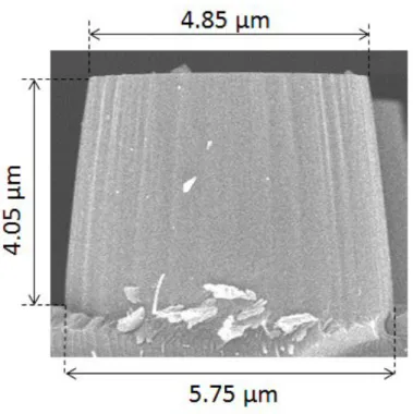
The final dimensions of the pillars were measured by scanning electron microscopy (SEM-FEG, Fig. 1). Pillars have a truncated cone shape charac-terized by an semi-angle of 96 ± 0.5, an upper diameter of 4,8±0.1 µm, and a height of about 4±0.005 µm. Overall the pillars are very homogeneous in dimension with an aspect ratio slightly larger than 1:1. Let us pay attention that lines are visible in the pillar geometry. These lines are consecutive to the fabrication, either resulting from mask irregularities or from RIE.
2.2. Experimental set-up
Compression experiments were performed using an in-situ SEM indenter (Alemnis Gmbh), first developed by Rabe et al [42]. It is installed in a Zeiss DSM 962 SEM. Indentation in SEM allows real time visualization of the de-formation of material under loading as well as easy positioning of the pillars beyond optical imaging resolution. The apparatus is displacement-controlled (piezo actuator) with a feedback loop control. Displacement-controlled de-vices allow load jumps to be avoided during micropillar compression of brittle materials, which can occur during load-controlled tests. A more detailed de-scription of the SEM indenter can be found in [42]. A 10um diameter flat punch was used. The acceleration voltage applied was between 5 and 10kV. All the experimental compressions were performed with a displacement speed of 100nm/s at loading and unloading, with a maximum displacement of 6um. More than 8 micro-compression tests were performed with excellent repro-ducibility, as shown in Fig 2.
The first question arising with in situ SEM micro-compression testing on materials like silica is the effect of electron beam on mechanical properties.
Mackovic et al [43] reported e-beam-induced densification as well as pro-nounced plasticity during beam-on mechanical testing on silica nanospheres with a diameter of 200 nm. Their experiments were performed in a TEM for which beam current density is significantly higher than with the SEM used in this paper. Moreover, their samples were submicrometric, whereas silica pillars studied here are 5 µm in diameter. It can thus be expected that the electron beam has a negligible impact on the global mechanical properties of silica. Any possible effects would be localized to the pillar surface. The good reproducibility of experiments performed using different irradiation ex-posure times (from 1 min to more than 20 min in a given case) supports this assertion. Moreover, SEM in-situ beam-off compressions performed on the same samples yield similar results.
2.3. Finite Element Modelling
Compression tests are modelled using the elliptic constitutive model [24], which makes possible to reproduce densifification-induced hardening. This constitutive model has been extensively detailed in our previous papers [31, 44], thus only the most important details are given here. The yield criterion is written : f (σij) = q qc !2 + p pc !2 − 1 (1)
where p is hydrostatic pressure, pc is the hydrostatic pressure limit, q is von Mises stress and qc the von Mises shear stress limit. With this yield criterion we use an associative flow rule. The densification-induced hardening is modelled by taking into account an increase of the hydrostatic limit pcwith permanent densification (i.e. a decrease of the void volume fraction φ). With
this void volume fraction the saturation process can be taken into account when φ → 0.
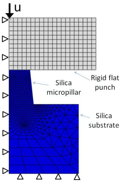
Calculations have been performed with the Finite Element Software Abaqus [45] using 2D axisymmetric elements and a finite transformation formulation based on the multiplicative decomposition of the deformation gradient into an elastic and a plastic part and the Jauman objective stress rate. An im-plicit FE scheme is used. The flat punch is a rigid body. The compression process is modelled by prescribing a vertical displacement to the flat punch. The friction coefficient acting betwen the punch and the pillar is assumed to be 0.1 (using the augmented Lagrangian method). Note that tests have been run with friction coefficient of 0.2 and also assuming a frictionless con-tact, but there was no differences observed on the force-displacement curve. The mesh is shown in figure 3. Note that the silica substrate is explicitly meshed to avoid any errors in the evaluation of its compliance, but the device compliance is not taken into account. Hence, in order to compare experimen-tal and FE-computed force-displacement curves, the device compliance has been identified using the elastic part of the load-displacement curve (Fig 4) assuming a Young’s moudulus of 70 GPa. Note that the pressure- and density-dependence of fused silica elastic properties [46, 47, 48] has not been taken into account in FE calculations as we have already observed that it only slightly affects the load-displacement curve [44]. Finally it has to be noticed that pillar geometrical imperfections as shown in Fig 1 - lines at the pillar periphery and slight defects at the basis of the pillar - are not considered in the FE model.
3. Results
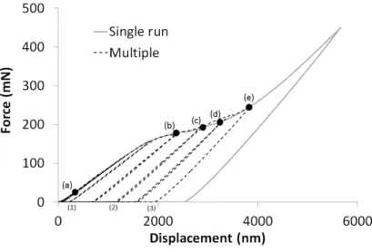
Typical raw results of compression tests are shown in Fig 4. We labelled single run the direct compression to maximum load. The first part is linear and corresponds to the expected elastic regime. Then the slope decreases suddenly, indicating the onset of plastic yielding. In this second part, de-limited by points (b) and (d), the slope remains constant. The third part, which is the last loading part, corresponds to a continuously increasing slope until the chosen unloading point is reached. The second curve in this graph, entitled multiple, has been run to investigate potential unloading hysteresis. The partial unloading cycles appear purely elastic and no such hysteresis is observed. After the partial unload-load cycle has been completed, further loading proceeds on the same load-displacement curve.
Consequently shapes of post-mortem pillars can be investigated as a func-tion of the prescribed strain level (Fig 5). The results show that when pushed into large axial strain amorphous silica experiences large radial strain as well. They confirm the radial expansion already observed by Lacroix et al [26] and Wakabayashi et al [35].
The apparent simplicity of micro-compression experiments should allow measurement of the true stress-strain curve and should give some new insights on shear-hardening [49]. Unfortunately, determining true stress-strain curves with pillar compression experiments is a difficult issue in the case of silica. A first issue is the contribution of the substrate. With silicate glasses, it is necessary to take into account the elastic deformation of the substrate, which is often negligible in the case of crystalline metals. Here we have extracted substrate stiffness from FE results. A second issue is the variation
of pillar section during straining. For crystalline metals plastic deformation is a volume conservative process and elastic deformation is negligible, so that pillar expansion is easy to calculate. For silica it is rather different as significant plastic densification can occur and elastic deformation is not negligible.
As first approximate analysis, in a purely kinematic picture, we can con-sider the usual additive decomposition of the deformation into elastic and plastic parts. The radial strain rate during compression obeys :
˙
εr = − (ν ˙εez + κ ˙ε p
z) (2)
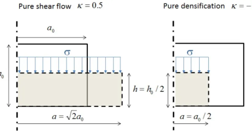
where εr is the radial deformation, εez is the elastic axial deformation, εpz is the plastic axial deformation, ν is the Poisson ratio and κ is the ratio of the plastic radial expansion over axial plastic deformation. For metals plastic deformation is isochoric (constant volume) so that κ = 0.5. For silica, due to densification, one expects κ < 0.5. In the extreme case of pure densification, i.e. in complete absence of shear flow κ, the plastic deformation tensor is spherical, so that κ = −1 (Fig 7). True stress-strain curves derived from raw data using values of κ ranging from 0.5 (isochoric) to −1 (pure densification) are plotted in Fig 8. Depending on κ, a significant apparent strain-hardening could be deduced.
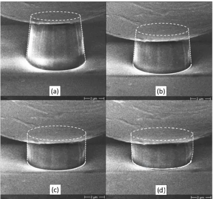
To ascertain the value of κ, we have developed a method based on the analysis of the in situ SEM images during straining for a direct evaluation of pillar section at large strains. Series of snapshots of the pillars during strain-ing have been recorded. A video is available as supplementary materials and some snapshot are presented in Fig 6. The snapshots were taken as marked on the load-displacement curve. The conical shape of the pillars plays a
ma-jor role during compression because it contributes to some heterogeneity of the strain field [26]. The upper half of the pillar enters the plastic regime when the lower half still behaves elastically. Combining that with the inter-action between the pillar bottom and the substrate, a heterogeneous radial expansion is observed along the height. More precisely, the pillar taper angle gradually disappears, making the pillars more cylindrical as shown on Fig 6 (SEM-image c). At very large uniaxial strains, the taper angle can even become slightly negative (SEM-image d).
The pillar contours were measured using a contrast-based image segmen-tation algorithm. Because of the view angle, the pillar is partly hidden by the flat punch so that it was not possible to measure the top section. Based on the SEM recording, we assumed that the pillar keeps a truncated cone shape during straining. Under this assumption, the mean pillar section was evaluated at each strain value. Results are presented in Fig 8. It appears that the yield stress is around 7 GPa, in agreement with our previous eval-uations [24, 26]. Moreover, our results demonstrate experimentally that the yield stress is independent of strain at least up to a strain of 0.4. This means that there is neither shear hardening nor softening.
Finally we note that some radial cracks can be observed in image (3) of Fig 5. Similar radial cracks have been already found by Lacroix et al [26], in post-mortem observations and for a much lower strain level. The video provided as a supplementary material clearly shows that this incipient radial cracking occurs during straining and that these cracks do not propagate during unloading. From the video, it is possible to determine the point of the loading curve for which the first crack event is observed. It roughly
corresponds to point (e) of Fig 4.
4. Discussion
The results confirm that at the scale of a few microns, amorphous sil-ica can undergo large uniaxial plastic strain up to 0.5 and more [26, 35]. Compared to the initial free volume, this value implies that the deforma-tion mechanism predominantly involves homogeneous shear flow. Indeed a purely densifying plasticity would lead to decreasing pillar cross-section dur-ing uniaxial compression as sketched in Fig 7. We conclude that densification cannot be the only deformation mode for silica plasticity at room tempera-ture and that homogeneous shear flow has to be taken into account on an equal footing.
In the approximate, purely kinematic analysis developed above, we find good agreement with the data for κ = 0.4. This is close to the 0.5 value expected for volume conservative plastic deformation and differs starkly from the −1 value expected for pure densification. In fact, 0.4 is a lower bound for κ because radial expansion in the lower part of the pillar is constrained by the substrate, so that Eq. (2) is questionable in this region. Thus κ could be even somewhat closer to the upper limit 0.5.
For a more accurate analysis, the load-displacement curve was computed using the constitutive relation we developed earlier [24]. Comparison with the data (Fig. 9) shows a very good agreement up to large strains. The discrepancy above 2 µm displacement may result from a modification of the mechanical behavior at very large strains or from the development of cracks at the bottom of the pillar, facilitating radial expansion. Indeed, in the
sim-ulations we find that axial as well as radial strains are not homogeneously distributed in the pillar (Fig. 10). Due to the slightly asymmetric geome-try and the boundary conditions at the top and bottom of the pillar, strong strain gradients are predicted. In view of the small size of the sample, ex-perimental mapping of these gradients is a presently insuperable challenge for local characterization methods [23, 32, 20]. The calculated densification distributions are plotted in 11. Densification becomes significant only once pillar height has been reduced by more than a half, i.e. when the pillar has been significantly strained. This suggests that for uniaxial compression a standard isochoric plasticity model could be used. To check that, FE calcu-lations have been run using a pure shear flow constitutive model based on J2 associated plasticity, with the same yield stress (qc) as used in the ellip-tic constitutive model. The calculated load-displacement curve is plotted in Fig 9 and we find that it matches the experimental curves reasonably well. Of course, the J2 model does not account for the various features of plastic deformation associated with the densifying behavior of silica, especially in more confined loadings such as indentation or hydrostatic compression.
Radial cracks are observed at large strains (Fig 5 3 and video in supple-mentary material). From the simulations, we can evaluate that the orthora-dial stress is approximately 6 GPa in the pillar periphery when the cracks occur (Fig 11). This high level of tensile stress is not expected in pure uniax-ial compression. It is a consequence of the truncated cone shape of the pillars and the substrate constraint that limits radial expansion at the bottom. The pillar accommodates plastic yielding with a height-dependent radial expan-sion. In the upper part, the pillar is free to expand and limited tensile stresses
are created. In the middle section of the pillar however, constraint is pro-vided by both the upper part of the pillar and the substrate. It is in this section that cracks open up, but their propagation is stopped very rapidly as only the periphery is under orthoradial tensile stresses. The crack initiation conditions are not well defined. For instance, the axial lines are visible on the pillar flanks (Fig 1) resulting from pillars fabrication may affect initiation of these radial cracks. We find a high tensile strength of 6 GPa which differs no-tably from our previous evaluation (1 GPa) [26]. The difference makes sense in view of the known sensitivity of crack initiation to water vapor and the strongly reduced water vapor pressure in the SEM. For example, subthresh-old indents made under dry nitrogen undergo crack pop-in as soon as they are exposed to the ambient [51]. Alternatively impact of instrument stiffness or an alignment issue inducing bending or plastically-enhanced buckling [44] may be involved. This observation opens up for further measurements with variable vapor pressure, for better insight into crack nucleation in relation to local plasticity and brittleness.
Our major conclusion is that there is no measurable shear strain hard-ening, in contrast to the observation by Wakabayashi et al [35]. In fact quantitative evaluation of the uniaxial stress state in the DAC is difficult due to the presence of the pressure medium and the friction on the diamond faces. The consequence of this absence of shear-hardening is that silica can-not resist any additional shear stress once shear flow has been initiated. This may lead to localisation, or at least to damage initiation [50, 41]. Interest-ingly, when in 1964 Marsh suggested that plastic flow is the limiting process for glass strength [5], he explicitly observed that silicate glasses should be
non work-hardening because of their random structure. As a result there is no stabilizing mechanism at the yield point and failure is catastrophic. Therefore micro-scale investigations based on shear loading are very promis-ing candidates for progress in our understandpromis-ing of the actual crack initiation mechanisms in silicate glasses.
5. Conclusions
Based on displacement-controlled in situ SEM uniaxial compression tests, we have been able to deform silica pillars to large strains without unstable crack propagation. A true stress-strain curve is obtained from the direct measurement of the cross section. In situ testing also makes it possible to identify events leading to crack nucleation during straining or unloading. It is shown here that cracks nucleate in the pillar periphery where tensile stresses reach very high values. The 6 GPa strength reached here considerably exceeds the 1 GPa value measured in a different set-up [26]. It is likely due to the low water vapor pressure in the SEM environment but could also be impacted by the different instrument stiffness. Further work is needed.
The radial expansion of the pillar during compression, backed by the FEM results, directly demonstrate that plastic deformation of silica under uniaxial compression is mainly due to homogeneous shear flow, even if some densification does occur. Of course, more densification is expected in more confined geometries such as with indentation. This result highlights the need for an accurate constitutive equation. The elliptic constitutive model makes it possible to reproduce uniaxial compression load-displacement curves, but a simpler model using a shear-based perfectly plastic behavior yields similar
results regarding the force-displacement curve. To go further in constitutive modeling of silica plasticity, further inputs from advanced micromechanics experiments [53, 17] and atomistic simulations [52] are required.
The yield stress is found around 7 GPa, in good agreement with our previous results. The absence of shear-hardening, even at large strains, is consistent with the expected plastic deformation processes in glasses. Inter-estingly, this means that through plastic flow silica can dissipate a great deal of external energy under compressive loading: this property could be useful in nanoscale structural engineering. Macroscopic brittleness is avoided at this scale as very high tensile stresses (greater than 6 GPa) are required to nucleate cracks. However, as pointed out by Marsh [5], the absence of shear hardening means that silica (and silicate glasses) are devoid of stabilization mechanisms at the yield point which leads to catastrophic failure under pure tensile loading – hence brittleness.
Acknowledgements
This work was supported in part by the French National Research Agency (ANR) under contracts ANR-13-BS09-0012-01 and ANR-12-BS04-0004-03. The authors are grateful to FEMTO-ST platforms for their help in pillars fabrication. G. Kermouche thanks Rhone-Alpes Region for the financial sup-port associated to his sabbatical leave at McGill University during which this paper was written. The authors wish to thank D. Tumbajoy for his help on mico-compression experiments and K. Thomas for helpful discussions on the content of this paper.
[1] A.S. Argon, R.F. Bartholomew, F.M. Ernsberger, S.W. Freiman, and H.M. Gardon, R.and Garfinkel. Glass Science and Technology, Elasticity and Strength in Glasses, volume 5. Uhlmann, D.R. and Kreidl, N.J., 1980.
[2] L. Wondraczek, J.C. Mauro, J. Eckert, U. Khn, J. Horbach, J. Deubener, and T. Rouxel. Towards ultrastrong glasses. Advanced Materials, 23(39):4578–4586, 2011.
[3] C.R. Kurkjian, P.K. Gupta, and R.K. Brow. The strength of silicate glasses: What do we know, what do we need to know? International Journal of Applied Glass Science, 1(1):27–37, 2010.
[4] E.W. Taylor. Plastic deformation of optical glasses. Nature, 163:323– 325, 1949.
[5] D.M. Marsh. Plastic flow in glass. Proc. R. Soc. Lond. A, 279:420–435, 1964.
[6] F.M. Ernsberger. Role of densification in deformation of glasses under point loading. J. Am. Ceram. Soc., 51:545–547, 1968.
[7] A. Arora, D.B. Marshall, B.R. Lawn, and M.V. Swain. Indentation deformation/fracture of normal and anomalous glasses. Journal of Non-Crystalline Solids, 31(3):415–428, 1979.
[8] P. Sellappan, T. Rouxel, F. Celarie, E. Becker, Houizot, P., and R. Con-radt. Composition dependence of indentation deformation and indenta-tion cracking in glass. Acta Materialia, 61(16):5949–5965, 2013.
[9] T. Sarlat, A. Lelarge, E. Sønderg˚ard, and D. Vandembroucq. Frozen capillary waves on glass surfaces: an afm study. The European Physi-cal Journal B-Condensed Matter and Complex Systems, 54(1):121–126, 2006.
[10] S.M. Wiederhorn and H. Johnson. Effect of pressure on the fracture of glass. Journal of Applied Physics, 42(2):681–684, 1971. cited By 5.
[11] D. Vandembroucq, T. Deschamps, C. Coussa, A. Perriot, E. Barthel, B. Champagnon, and C. Martinet. Density hardening plasticity and mechanical aging of silica glass under pressure: A Raman spectroscopic study. Journal of Physics Condensed Matter, 20:485221, 12 2008.
[12] T. Rouxel. Driving force for indentation cracking in glass: Composition, pressure and temperature dependence. Philosophical Transactions of the Royal Society A: Mathematical, Physical and Engineering Sciences, 373(2038), 2015.
[13] T. Deschamps, A. Kassir-Bodon, C. Sonneville, J. Margueritat, C. Mar-tinet, D. De Ligny, A. Mermet, and B. Champagnon. Permanent den-sification of compressed silica glass: A raman-density calibration curve. Journal of Physics Condensed Matter, 25(2), 2013.
[14] F.M. Ernsberger. Mechanical properties of glass. Journal of Non-Crystalline Solids, 25(1-3):293–321, 1977.
[15] K.W. Peter. Densification and flow phenomena of glass in indentation experiments. Journal of Non-Crystalline Solids, 5(2):103–115, 1970.
[16] J.D. Mackenzie and R.P. Laforce. High-pressure densification of glass and the effects of shear. Nature, 197(4866):480–481, 1963.
[17] S. Romeis, J. Paul, P. Herre, D. de Ligny, J. Schmidt, and W. Peukert. Local densification of a single micron sized silica sphere by uniaxial compression. Scripta Materialia, 2015.
[18] C.R. Kurkjian, G.W. Kammlott, and M.M. Chaudhri. Indentation be-havior of soda-lime silica glass, fused silica, and single-crystal quartz at liquid nitrogen temperature. Journal of the American Ceramic Society, 78(3):737–744, 1995.
[19] R. Limbach, A. Winterstein-Beckmann, J. Dellith, D. Moncke, and L. Wondraczek. Plasticity, crack initiation and defect resistance in alkali-borosilicate glasses: From normal to anomalous behavior. Journal of Non-Crystalline Solids, 417-418:15–27, 2015.
[20] P. Malchow, K.E. Johanns, D. Mncke, S. Korte-Kerzel, L. Wondraczek, and K. Durst. Composition and cooling-rate dependence of plastic defor-mation, densification, and cracking in sodium borosilicate glasses during pyramidal indentation. Journal of Non-Crystalline Solids, 419:97–109, 2015.
[21] S. Yoshida, H. Sawasato, T. Sugawara, Y. Miura, and J. Matsuoka. Ef-fects of indenter geometry on indentation-induced densification of soda-lime glass. Journal of Materials Research, 25(11):2203–2211, 2010.
de-formation mechanism in glass: Densification versus shear flow. Journal of Applied Physics, 107(9), 2010.
[23] A. Perriot, V. Martinez, L. Grosvalet, Ch. Martinet, B. Champagnon, D. Vandembroucq, and E. Barthel. Raman microspectrocopic charac-terization of amorphous silica plastic behavior. J. Am. Ceram. Soc., 89:596–601, 2006.
[24] G. Kermouche, E. Barthel, D. Vandembroucq, and Ph. Dubujet. Me-chanical modelling of indentation-induced densification in amorphous silica. Acta Materialia, 56(13):3222–3228, 2008.
[25] K-L. Johnson. Contact Mechanics. Cambridge University Press, 1985.
[26] R. Lacroix, G. Kermouche, J. Teisseire, and E. Barthel. Plastic defor-mation and residual stresses in amorphous silica pillars under uniaxial loading. Acta Materialia, 60(15):5555–5566, 2012.
[27] J.C. Lambropoulos, S. Xu, and T. Fang. Constitutive law for the densi-fication of fused silica, with applications in polishing and microgrinding. J. Am. Ceram. Soc., 79:1441–1452, 1996.
[28] K.R. Gadelrab, F.A. Bonilla, and M. Chiesa. Densification modeling of fused silica under nanoindentation. Journal of Non-Crystalline Solids, 358(2):392–398, 2012.
[29] V. Keryvin, S. Gicquel, L. Charleux, J.-P. Guin, M. Nivard, and J.-C. Sanglebuf. Densification as the only mechanism at stake during inden-tation of silica glass? Key Engineering Materials, 606:53–60, 2014.
[30] B. Champagnon, C. Martinet, M. Boudeulle, D. Vouagner, C. Coussa, T. Deschamps, and L. Grosvalet. High pressure elastic and plastic defor-mations of silica: In situ diamond anvil cell raman experiments. Journal of Non-Crystalline Solids, 354(2-9):569–573, 2008.
[31] A. Perriot, E. Barthel, G. Kermouche, G. Qurel, and D. Vandembroucq. On the plastic deformation of soda-lime glass-a cr3+ luminescence study of densification. Philosophical Magazine, 91(7-9):1245–1255, 2011.
[32] Y.-F. Niu, K. Han, and J.-P. Guin. Locally enhanced dissolution rate as a probe for nanocontact-induced densification in oxide glasses. Langmuir, 28(29):10733–10740, 2012.
[33] M. D. Uchic, D. M. Dimiduk, J. N. Florando, and W. D. Nix. Sam-ple Dimensions Influence Strength and Crystal Plasticity. Science, 305(5686):986–989, 2004.
[34] S.M. Han, C. Xie, and Y. Cui. Microcompression of fused silica nanopil-lars synthesized using reactive ion etching. Nanoscience and Nanotech-nology Letters, 2(4):344–347, 2010.
[35] D. Wakabayashi, N. Funamori, and T. Sato. Enhanced plasticity of silica glass at high pressure. Physical Review B - Condensed Matter and Materials Physics, 91(1), 2015.
[36] P. Franciosi, M. Berveiller, and A. Zaoui. Latent hardening in copper and aluminium single crystals. Acta Metallurgica, 28(3):273–283, 1980.
[37] A. Bolshakov and G.M. Pharr. Influences of pileup on the measure-ment of mechanical properties by load and depth sensing indentation techniques. Journal of Materials Research, 13(4):1049–1058, 1998.
[38] C. Fusco, T. Albaret, and A. Tanguy. Role of local order in the small-scale plasticity of model amorphous materials. Physical Review E -Statistical, Nonlinear, and Soft Matter Physics, 82(6), 2010.
[39] B. Mantisi, A. Tanguy, G. Kermouche, and E. Barthel. Atomistic re-sponse of a model silica glass under shear and pressure. European Phys-ical Journal B, 85(9), 2012.
[40] S. Yoshida, S. Iwata, T. Sugawara, Y. Miura, J. Matsuoka, A. Erra-part, and C.R. Kurkjian. Elastic and residual stresses around ball in-dentations on glasses using a micro-photoelastic technique. Journal of Non-Crystalline Solids, 358(24):3465–3472, 2012.
[41] C. Tekoglu, J.W. Hutchinson, and T. Pardoen. On localization and void coalescence as a precursor to ductile fracture. Philosophical Trans-actions of the Royal Society A: Mathematical, Physical and Engineering Sciences, 373(2038), 2015.
[42] R. Rabe, J.-M. Breguet, P. Schwaller, S. Stauss, F.-J. Haug, J. Patschei-der, and J. Michler. Observation of fracture and plastic deformation dur-ing indentation and scratchdur-ing inside the scanndur-ing electron microscope. Thin Solid Films, 469-470(SPEC. ISS.):206–213, 2004.
[43] M. Ma?kovi?, F. Niekiel, L. Wondraczek, and E. Spiecker. Direct ob-servation of electron-beam-induced densification and hardening of silica
nanoballs by in situ transmission electron microscopy and finite element method simulations. Acta Materialia, 79:363–373, 2014.
[44] R. Lacroix, V. Chomienne, G. Kermouche, J. Teisseire, E. Barthel, and S. Queste. Micropillar testing of amorphous silica. International Journal of Applied Glass Science, 3(1):36–43, 2012.
[45] Simulia. Abaqus Explicit User’s manual. Dassault Systemes, 2013.
[46] K. Kondo, S. Iio, and A. Sawaoka. Nonlinear pressure dependence of the elastic moduli of fused quartz up to 3 gpa. Journal of Applied Physics, 52(4):2826–2831, 1981.
[47] T. Deschamps, J. Margueritat, C. Martinet, A. Mermet, and B. Cham-pagnon. Elastic moduli of permanently densified silica glasses. Scientific Reports, 4, 2014.
[48] V. Keryvin, J.-X. Meng, S. Gicquel, J.-P. Guin, L. Charleux, J.-C. San-glebuf, P. Pilvin, T. Rouxel, and G. Le Quilliec. Constitutive modeling of the densification process in silica glass under hydrostatic compression. Acta Materialia, 62(1):250–257, 2014.
[49] D. Kiener, P.J. Guruprasad, S.M. Keralavarma, G. Dehm, and A.A. Benzerga. Work hardening in micropillar compression: In situ experi-ments and modeling. Acta Materialia, 59(10):3825–3840, 2011.
[50] K. Nahshon and J.W. Hutchinson. Modification of the gurson model for shear failure. European Journal of Mechanics, A/Solids, 27(1):1–17, 2008.
[51] A.T. Taylor and M.J. Matthewson. The fatigue behavior of Vickers indentations in fused silica optical fiber. Proc. 46th Int. Wire & Cable Symp., 910-916, 1997.
[52] B. Mantisi, G. Kermouche, E. Barthel, and A. Tanguy. Impact of pres-sure on plastic yield in amorphous solids with open structure. Physical Review E, In press, 2016.
[53] A. Kassir-Bodon, T. Deschamps, C. Martinet, B. Champagnon, J. Teis-seire, and G. Kermouche. Raman mapping of the indentation-induced densification of a soda-lime-silicate glass. International Journal of Ap-plied Glass Science, 3(1):29–35, 2012.
Figure 4: Load-displacement curves : single run and multiple loading-unloading yield sim-ilar results. No significant hysteresis is observed when using multiple loading-unloading, whatever the displacement value.
Figure 5: Micropillar residual shape for different load values. Inset numbers refer to the load-displacement curve in Fig 4
Figure 6: Pillars deformation during straining. Inset letters (a),(b), (c) and (d) are related to some points of the load-displacement curve in Fig 4.
Figure 7: Sketch of the side-view of a unaxially loaded cylinder of initial radius a0 and initial height h0. Left-side : pure shear flow is an isochoric transformation and is char-acterized by κ = 0.5. In this case a significant radial expansion is expected. Right-side : pure densification is a transformation leading to the same contraction in all directions. Pure densification is a spherical deformation state and is thus characterized by κ = −1. In this case, plastic flow will lead to a decrase of the cylinder radius during straining
Figure 8: True stress-strain curves. κ is the coefficient that relates pillars’ radial defor-mation to axial plastic defordefor-mation. Black dots are stress-strain points computed using the actual average pillar section from in-situ SEM observations. Letters under these black dots refer to Fig 6.
Figure 9: Micro-compression testing - FEM vs Experiments. A good agreement is observed using the elliptic constitutive model, but also with a basic shear-driven plasticity model.
Figure 10: Computed pillar’s deformation during straining using the elliptic constitutive model [24]. Left side of each image is the axial strain distribution and righ-side is the radial strain distribution. Strain field are rather heterogeneous. The radial strain distribution is in good agreement with the radial expansion observed experimentally. Inset letters (b), (c), (d) and (e) are related to some points of the load-displacement curve in Fig 4
Figure 11: Left side of each image is densification distribution upon and right-side is maximum principal stress distribution as calculated by FEM. Inset letters (c) and (e) are related to a point of the load-displacement curve 4. The densification field is rather heterogeneous but can reach large values at large strains. it is observed that high tensile stress (up to 6 GPa) are located at the pillar’s periphery that might promote radial cracks nucleation and subsequent propagation during straining (see supplementary-materials)


![Figure 10: Computed pillar’s deformation during straining using the elliptic constitutive model [24]](https://thumb-eu.123doks.com/thumbv2/123doknet/11491939.293031/34.918.171.757.408.615/figure-computed-pillar-deformation-straining-using-elliptic-constitutive.webp)

