HAL Id: hal-01108217
https://hal.archives-ouvertes.fr/hal-01108217
Submitted on 22 Jan 2015
HAL is a multi-disciplinary open access
archive for the deposit and dissemination of
sci-entific research documents, whether they are
pub-lished or not. The documents may come from
teaching and research institutions in France or
abroad, or from public or private research centers.
L’archive ouverte pluridisciplinaire HAL, est
destinée au dépôt et à la diffusion de documents
scientifiques de niveau recherche, publiés ou non,
émanant des établissements d’enseignement et de
recherche français ou étrangers, des laboratoires
publics ou privés.
Filtering slot antenna using coupled line resonator
Kevin Nadaud, Dominique Lo Hine Tong, Erwan Fourn
To cite this version:
Kevin Nadaud, Dominique Lo Hine Tong, Erwan Fourn. Filtering slot antenna using coupled line
resonator. European Microwave Integrated Circuit Conference (EuMIC), Oct 2014, Rome, Italy.
pp.1500 - 1503, �10.1109/EuMC.2014.6986733�. �hal-01108217�
Filtering Slot Antenna Using
Coupled Line Resonator
Kevin Nadaud
IETR UMR 6164/University of Nantes Nantes, France
Dominique Lo Hine Tong
Technicolor Connected Home Rennes, France
Erwan Fourn
IETR UMR 6164/INSA of Rennes Rennes, France
Abstract—This paper presents the design of a novel slot filter-ing antenna suitable for modern electronic devices integratfilter-ing various wireless systems that have to coexist. The approach consists in feeding the slot antenna through a filtering microstrip-to-slot-line transition. This transition comprises a coupled line resonator which enables to create two out-of-band transmission zeros and by this way to increase drastically the frequency selectivity of the transition. As proof-of-concept, a slot filtering antenna has been designed for WLAN applications operating in the 2.4GHz band, by using the HFSSTM simulation tool.
A prototype has been also fabricated, using a low-cost FR4 substrate, where 2 antennas are printed on a board in order to accommodate the requirements of a 2×2 MIMO system.
Index Terms—Slot antenna, filtering antenna, coupled lines
I. INTRODUCTION
Home-networking devices such as set-top-boxes and media-gateways tend to embed more and more wireless systems in order to accommodate the increasing demand of new services, this with ever-growing quality and performance. To mention a few, the devices can integrate WiFi system, RF4CE remote control, DECT telephony, various home-automation radios operating in the 433/868/915MHz bands etc. This obviously raises tremendous problems of coexistence. The most common solution to mitigate these interference issues is currently to use discrete filters, placed upstream the antennas.
In the recent years, another way has been paved which consists in adding a filtering feature to antennas, making the antennas having a specific frequency selective response. The objective is to be more compact and cost effective than usual solutions that consist in cascading in series filters and antennas. For instance, [1] proposes a filtering patch antenna excited by a T-shape feeding line in order to provide an elliptic response; in [2] patch antennas are synthesized and arranged in a way to feature a band-pass response; in [3]–[5] a filter is synthesized considering the last resonator as a radiating element.
In this paper another approach is proposed. From the basic slot antenna fed by a microstrip-to-slot-line (MSSL) transition, a filtering feature is integrated by adding a parallel coupled line resonator to the transition. This results in a compact antenna design exhibiting a pseudo-elliptic response.
The paper is organized as follows: section 2 introduces the concept of the proposed filtering MSSL transition, section 3 describes how this transition is used to feed an antenna, section
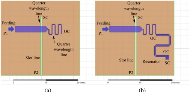
Feeding Quarter wavelength line P1 P2 OC SC Quarter wavelength line Slot line (a) Feeding Quarter wavelength line Resonator P1 P2 OC OC SC SC Slot line (b)
Figure 1. Usual MSSL transition (a) and filtering transition based on coupled lines (b). Lres Lsym Lopen
OC
OC
Figure 2. Topology of an asymmetrical coupled line resonator.
4 the design and performances of a filtering slot antenna in the 2.4GHz WLAN band, printed twice on a board for a 2×2 MIMO (Multiple Input Multiple Output) application.
II. FILTERING MICROSTRIP-TO-SLOT TRANSITION A. Usual MSSL transition
The MSSL transition used here is based on Knorr’s transi-tion [6]. To maximize the coupling between the two transmis-sion lines, two conditions have to be respected at the cross-junction:
• the microstrip line has to present a short circuit (SC), • the slot line has to present an open circuit (OC).
These two requirements can be met by using quarter wave-length lines (Fig. 1a) and in that case a wide band transition can be achieved [6] (Fig. 3).
S11 , S21 (d B) −30 −25 −20 −15 −10 −5 0 Frequency (GHz) 1,5 2 2,5 3 3,5 Usual Transition Filtering Transition S21 S11
Figure 3. Simulated S parameters of the usual and filtering transitions.
B. Filtering MSSL transition
To make this transition frequency selective, the idea is to keep the microstrip line presenting a short-circuit at the cross-junction in the band of interest, but to ensure that the microstrip line presents an open-circuit in the frequency band to attenuate. To deal with these requirements, the use of a parallel coupled line resonator [5], [7] is proposed. The latter is placed at the end of the quarter wavelength microstrip line, Fig. 1b.
The resonator consists in a pair of coupled quarter wave-length lines that has been meandered for the purpose of miniaturization. The resonator acts here as an impedance inverter and enables to present the requested impedance at the transition cross-junction. Once the requested in-band and out-of-band impedances are achieved two transmission zeros are created at each side of the central frequency. The position of the zeros can be set independently by adjusting the coupled lines parameters. Width and isolation of these lines enable to tune the zero positions. For instance, the larger the width and isolation the closer the zero positions to the central frequency. The length of the open circuited line (Lopen) of the
res-onator can be adjusted to avoid the symmetrical position of the zeros Fig. 2. The short-circuited line, Lres, has to be set
to quarter wavelength line.
This filtering transition has been simulated and compared to the usual one, this using a low-cost FR4 substrate (thickness 1 mm, relative permittivity 4.4, dielectric loss 0.02).
As can be seen in Fig. 3, the transition with the resonator is more frequency selective than the usual one. The achieved rejection is 20 dB at the frequencies of the transmission zeros. In the passing band, there is an additional attenuation provided by the resonator, resulting in an insertion loss 1 dB higher than in the usual transition one.
III. FILTERING SLOT ANTENNA DESIGN
The transition described before is used to feed an open ended quarter wavelength slot antenna. The length of the slot
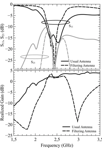
S11 (d B) −25 −20 −15 −10 −5 0 Re ali ze d Ga in (d B) −40 −30 −20 −10 0 10 Frequency (GHz) 1,5 2 2,5 3 3,5 Usual Antenna Filtering Antenna
Figure 4. Simulated reflection coefficient and realized gain for a slot antenna fed respectively by a usual and a filtering transition.
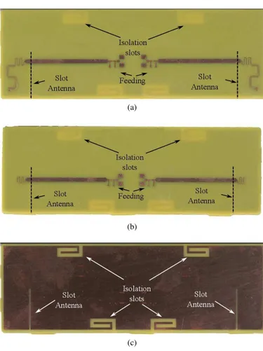
(a)
(b)
(c)
Figure 5. Top side of the board with two filtering slot antennas (a), top side of the board with two usual slot antennas (b) bottom side of both boards (c).
is 19.5 mm and the width 0.3 mm. An usual slot antenna has also been simulated for comparison.
Fig. 4 shows the simulated results of both antennas. One can notice the reflection coefficient for the filtering antenna (200 MHz band at -10 dB) is wider than the usual antenna (100 MHz band at -10 dB), thanks to the benefit of the resonator added which acts as a two-pole filter [1]. On the
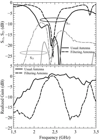
S11 , S21 (d B) −25 −20 −15 −10 −5 Usual Antenna Filtering Antenna S11 S21 Re ali ze d Ga in (d B) −25 −20 −15 −10 −5 0 5 Frequency (GHz) 1,5 2 2,5 3 3,5 Usual Antenna Filtering Antenna
Figure 6. Simulated reflection coefficient, isolation and realized gain for the board containing two antennas.
realized gain responses, the effect of the resonator is also remarkable. Like for the transition, the filtering antenna has two radiation zeros. The rejection at the frequencies of the zeros for the filtering antenna is 25 dB higher than for the usual one. In the passing band, the gain of the filtering antenna is equal to the usual antenna gain.
IV. FILTERING ANTENNA FORWLANAPPLICATION A. Simulations
As proof-of-concept a filtering antenna has been realized in the 2.4GHz band the WLAN IEEE-802.11b/g/n standard. This antenna is printed twice on a FR4-based board in order to address a 2*2 MIMO application (Fig. 5). This board has a size of 120×40 mm2 and contains 4 slots which the role is to
ensure the high isolation between the antennas, as required by MIMO systems. The width of the coupled lines and the gap between them is 0.2 mm. The unfolded length of the resonator is 18 mm.
The simulation results of the antennas are shown in Fig. 6. The impedance matching band at -10dB of the filtering antenna is around 200 MHz. At the frequencies of the two radiation zeros (1.8 and 3 GHz), the rejection of the filtering antenna is 17 dB higher than the usual antenna one. Regarding the radiation performance, in term of efficiency the usual antenna (70%) features slightly a better performance than the filtering
Effi cie nc y (% ) 0 20 40 60 80 Frequency (GHz) 1,5 2 2,5 3 3,5 Usual Antenna Filtering Antenna
Figure 7. Simulated antenna efficiency the usual and filtering slot antennas.
(a)
(b)
Figure 8. Simulated radiation patterns of the usual (a) and filtering slot antennas (b). The slot is oriented along the X axis.
antenna (65%). Therefore the peak gain is also slightly higher for the usual antenna (2 dBi) than for the filtering antenna (1.5 dBi). The 3D radiation patterns plotted in Fig. 8 are very similar in both antenna configuration. The differences observed come from the isolation slot locations which differ from an antenna board to another. For the usual antenna, in the worst case, the in-band isolation between antennas is around 17 dB, which complies with MIMO application request. This
Re ali ze d Ga in (d B) −25 −20 −15 −10 −5 0 5 Frequency (GHz) 1,5 2 2,5 3 3,5 Usual Antenna Filtering Antenna S11 , S21 (d B) −25 −20 −15 −10 −5 0 Usual Antenna Filtering Antenna S11 S21
Figure 9. Measured reflection coefficient, isolation and realized gain of the usual and filtering antennas.
isolation is increased drastically in the center of the WLAN band, thanks to the slots added in the PCB ground plane. With the addition of the filter to the antenna the isolation response is quite similar.
B. Experimental validation
As illustrated in Fig. 9-10, the reflection coefficients, the zero locations and out-of-band gains are comparable between the simulation and measurement results. The isolation response is also similar to the simulation one. The wider matching band achieved for the usual antenna is assumed to come from the relative low isolation in the edges of the WLAN frequency band. Comparing the measured performances between usual and filtering antennas, the same trends as in simulation can be noticed, meaning: lower radiation efficiency and gain for the filtering antenna (30%, 0 dBi) than for the usual antenna (40%, 1.2 dBi). At the zeros frequencies, around 1.8 and 3 GHz, it is demonstrated a gain attenuation of around 18-20 dB relative to the in-band gain.
In general the measured performance are lower than the simulated ones, in terms of radiation efficiency and in-band gain. Several reasons explain these discrepancies: the measure-ment uncertainties, in particular the effects of the cables and connectors used which have not been taking into account in simulation; the printed circuit board manufacturing tolerances
Effi cie nc y (% ) 0 20 40 60 80 100 Frequency (GHz) 1,5 2 2,5 3 3,5 Usual Antenna Filtering Antenna
Figure 10. Measured antenna efficiency for the usual and filtering slot antennas.
in terms of etching and thickness. V. CONCLUSIONS
In this paper a novel filtering antenna is proposed consisting in associating properly an usual slot antenna with a coupled line resonator. The new slot antenna geometry enables to create two out-of-band radiation zeros. The frequencies of the latter can be fixed independently by tuning the resonator parameters. Around these zero frequencies a rejection close to 20dB is demonstrated, allowing the proposed filtering slot antenna to be used in wireless systems that have to reject efficiently out-of-band interfering signals.
ACKNOWLEDGMENT
This work has been supported by the French DGCIS (Direction Générale de la Compétivité de l’Industrie et des Services) through the European CATRENE Eureka cluster and the CORTIF project.
REFERENCES
[1] C.-K. Lin and S.-J. Chung, “A compact filtering microstrip antenna with quasi-elliptic broadside antenna gain response,” IEEE Antennas and Wireless Propagation Letters, vol. 10, pp. 381–384, 2011.
[2] F. Queudet, B. Froppier, Y. Mahe, and S. Toutain, “Integration of pass-band filters in patch antennas,” in European Microwave Conference, 2002. [3] C.-T. Chuang and S.-J. Chung, “Synthesis and design of a new printed filtering antenna,” IEEE Transactions on Antennas and Propagation, vol. 59, no. 3, 2011.
[4] C.-K. Lin and S.-J. Chung, “A compact simple structured filtering antenna utilizing filter synthesis technique,” in Asia Pacific Microwave Conference, 2010.
[5] C.-T. Chuang and S.-J. Chung, “New printed filtering antenna with selectivity enhancement,” in European Microwave Conference, 2009. [6] K. C. Gupta, R. Garg, and I. J. Bahl, Microstrip lines and Slotlines.
ARTECH House, 1979.
[7] C.-T. Chuang and S.-J. Chung, “A compact printed filtering antenna using a ground-intruded coupled line resonator,” IEEE Trans. Antennas Propag., vol. 59, no. 10, pp. 3630–3637, 2011.