HAL Id: hal-00459831
https://hal.archives-ouvertes.fr/hal-00459831
Submitted on 25 Jun 2019HAL is a multi-disciplinary open access archive for the deposit and dissemination of sci-entific research documents, whether they are pub-lished or not. The documents may come from teaching and research institutions in France or abroad, or from public or private research centers.
L’archive ouverte pluridisciplinaire HAL, est destinée au dépôt et à la diffusion de documents scientifiques de niveau recherche, publiés ou non, émanant des établissements d’enseignement et de recherche français ou étrangers, des laboratoires publics ou privés.
Pantopteron-4: a New 3T1R Decoupled Parallel
Manipulator for Pick-and-Place Applications
Sébastien Briot, Ilian Bonev
To cite this version:
Sébastien Briot, Ilian Bonev. Pantopteron-4: a New 3T1R Decoupled Parallel Manipulator for Pick-and-Place Applications. Mechanism and Machine Theory, Elsevier, 2010, 45 (5), pp.707-721. �hal-00459831�
Pantopteron-4: a New 3T1R Decoupled Parallel Manipulator
for Pick-and-Place Applications
Sébastien Briotand Ilian A. Bonev
Department of Automated Manufacturing Engineering École de technologie supérieure (ÉTS), Montreal, QC, Canada
sebastien.briot.1@ens.etsmtl.ca ilian.bonev@etsmtl.ca
Abstract— In this paper, a novel 4-DOF decoupled parallel manipulator with Schoenflies motions, called the Pantopteron-4, is presented. This manipulator is able to perform the same movements as the Isoglide4 or the Quadrupteron, but, due to its architecture which is made of three pantograph linkages, an amplification of the movements between the actuators and the platform displacements is achieved. Therefore, having the same actuators for both robots, the Pantopteron-4 displaces (theoretically) many-times faster than the Isoglide4 or the Quadrupteron, depending on the magnification factor of the pantograph linkages. Thus, this mechanism is foreseen to be used in applications where the velocities and accelerations have to be high, as in pick-and-place. First, the kinematics of the Pantopteron-4 is presented. Then, its workspace is analyzed. Finally, a prototype of the mechanism is shown and conclusions are given.
Index Terms — parallel manipulator, decoupling, kinematics, Schoenflies motions, singularity, workspace, design.
I. INTRODUCTION
Less than a decade ago, any known parallel robot, whatever its number of degrees of freedom (DOF), was inevitably associated with nonlinear highly-coupled kinematics, singularities, and a complex-shaped workspace. However, in May 2001, this fact was refuted by the discovery of a revolutionary simple 3-DOF translational parallel robot, with fully-decoupled input-output equations, disclosed by Gosselin and Kong in a Canadian provisional patent application [1]. Its simplest design is basically a Cartesian
robot and is therefore isotropic (its Jacobian matrix is diagonal and constant). Later in 2002, many
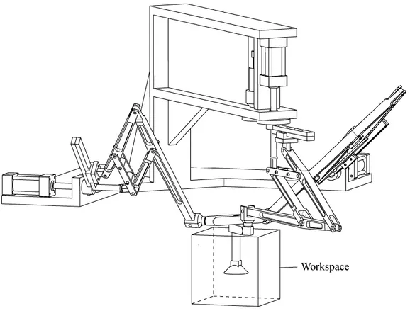
researchers proposed separately a large family of decoupled 3-DOF translational parallel mechanisms, all covered by the above-mentioned patent [2]-[6]. These works cleared the way for the creation of various decoupled parallel mechanisms.
The most prolific author on this subject, Gogu, wrote dozens of papers and even a 700-page manuscript [7] proposing isotropic architectures for nearly all combinations of translational and rotational degrees of freedom. Specifically, many efforts have been done in creating decoupled robots with Schoenflies motions [8]-[13] for pick-and-place applications, driven by the commercial success of the Delta [14] and Quattro [15] robots. Examples of decoupled 3T1R (three translational DOFs and one rotational DOF) structures are the Quadrupteron [11] and the Isoglide4 [13], shown in Fig. 1.
The basic Quadrupteron or Isoglide4, which are very similar, consists of four identical legs. Each leg has a base-mounted actuator, allowing translation along a fixed direction, and a planar chain. In these basic robots, linear actuators are employed and the displacements of three of them are directly proportional to the translational displacements of the mobile platform along a given Cartesian axis. The orientation of the end-effector is obtained by a scissors-like motion of the actuators.
(a) the prototype of Quadrupteron (courtesy of C.M. Gosselin)
(b) the Isoglide4 – CAD view (courtesy of G. Gogu)
Fig. 1. Some partially decoupled 3T1R parallel manipulators.
However, as we recently witnessed with the commercialization of the Quattro robot by Adept Technology [15], the only way to compete the hugely successful Delta pick-and-place robot [14] is to offer an even faster design. Hence, it would have been great if we could build a Quadrupteron or an Isoglide4 with an amplification factor. Not only would this robot be isotropic, but it may move several times faster than its linear actuators.
This paper is the first to provide such a solution through the use of pantographs. Of course, the proposed design is more complicated than the simple Quadrupteron or Isoglide4 of Fig. 1, but this seems to be a reasonable price to pay. Moreover, the new robot is only made of three identical legs, in contrast to other 3T1R decoupled parallel robots, which is a great advantage in terms of workspace volume and acceleration capacities. Indeed, the proposed design is the result of a large study on the synthesis of parallel manipulators using pantographs [16], [18]. One such manipulator was already successfully built and proved the viability of using pantographs [19].
described. Then, its workspace is studied and various design considerations are given. Finally, conclusions are drawn.
II. KINEMATICANALYSIS
A. Description of the architecture
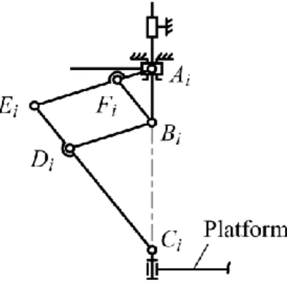
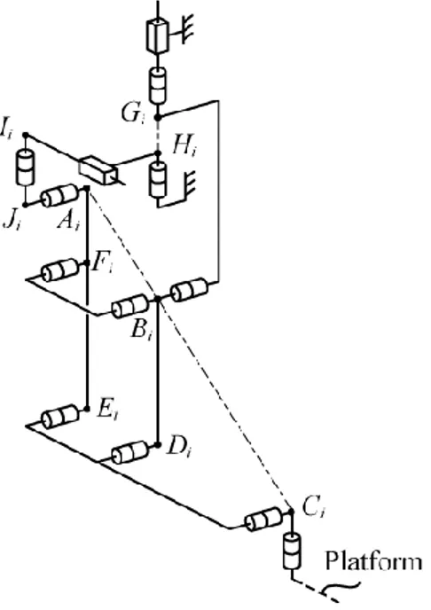
The architecture of the manipulator is illustrated in Fig. 2. It is composed of three legs which correspond to pantograph linkages (Fig. 3).
The pantograph is a mechanical system with two input points Ai and Bi and one output point Ci (in the
remainder of this paper, i = 1, 2, 3). These input points linearly control the displacement of the output point Ci. A kinematic analysis shows that a linear actuator connected with input point Bi controls the
vertical displacement of the output point Ci and one other linear actuator with an axis parallel to a1i
controls the displacements along the same axis. Note that these motions are completely decoupled, i.e., they can be carried out independently. The input/output relationships for displacements are linear and are determined by the magnification factor k of the pantograph (k = AiCi/AiBi). These properties of the
pantograph mechanism are used in the Pantopteron-4 manipulator.
For the Pantopteron-4, the actuators which allow the translational displacements are located at the prismatic joints 1i (Fig. 3), and the actuator that controls the orientation of the platform is located at the revolute joint 10,3. The directions of the prismatic joints 1i are orthogonal. All other joints are passive. Each pantograph linkage is attached to the platform at point Ci via a Cardan joint, the axes of each joint
12i being orthogonal. They are also connected to actuators 1i via a revolute joint, which allows the leg to have five DOFs: three translations and two rotations about the axes of the Cardan joint located at Ci. The
platform of the mechanism is not rigid, but made of two elements connected via a revolute joint. Such an architecture allows the manipulator to have four decoupled DOF. This will be now proved.
Fig. 2. Schematics of the Pantopteron-4 manipulator.
Fig. 3. Schematics of one leg of the Pantopteron-4 (i = 1, 2, 3).
B. Mobility analysis
Let x, y, z be the axes of the base frame (Fig. 2) and a1i, a2i and a3i the local frame attached to leg i
and another about the axis of joint 12,1). Therefore, each leg applies one wrench on the platform that constrains its displacements. This wrench is the reciprocal screw to the twists of each passive displacement of the platform.
We denote as e(ij) (j = 1 to 5) the unit screw corresponding to one of the passive displacements of the leg j. For leg 1, these screws, expressed in the base frame at point C1, can be written as [20]:
- for the translations along x, y and z, e1(1)
0 0 0 1 0 0
T, e2(1)
0 0 0 0 1 0
T and
T 1 0 0 0 0 0 ) 1 ( 3 e ;- for the rotations about the axes of joints 12,1 and 11,1,
T 0 0 0 sin sin sin cos cos 1 1 1 1 1 ) 1 ( 4 e and
0 sin 1 cos 1 0 0 0
T) 1 (
5
e ,
where 1 is the angle between the a11 axis and the y axis, and 1 represents the angle between vector a31
and the axis of joint 12,1.
The Plücker coordinates of the unit screws can be described in matrix E1 as
0 0 0 cos sin 0 0 0 0 sin sin sin os cos 1 0 0 0 0 0 0 1 0 0 0 0 0 0 1 0 0 0 1 1 1 1 1 1 1 ) 1 ( 5 ) 1 ( 4 ) 1 ( 3 ) 1 ( 2 ) 1 ( 1 c T T T T T e e e e e E1 (1)
The wrench r11 transmitted to the platform by the leg 1 is orthogonal to the twists composing the lines
of matrix E1:
x y z
T r r r11 11 11 0 0 0 11 r (2) with 1 11 sin x r (3a) 1 1 11 cos cos y r (3b) 1 1 11 sin cos z r (3c)Thus, r11 is a wrench of zero pitch (a pure moment).
Similarly, it is possible to find that the wrenches r1i transmitted to the platform by the legs when all
actuators are disconnected are all pure moments. Let Q be the matrix composed of these wrenches applied on the platform by the legs. The expression of Q in the base frame, and expressed at point O, is:
0 0 0 0 0 0 0 0 0 13 13 13 12 12 12 11 11 11 13 12 11 z y x z y x z y x T T T r r r r r r r r r r r r Q (4)
The expressions of wrenches r12 and r13 can be obtained using approaches similar to the previous one.
Analyzing the condition of orthogonality on the axes of joints 12i, it could be proven that angles i are
constrained to be equal to 0. Therefore, these terms disappear from Eq. (4), which becomes
0 0 0 0 sin cos 0 0 0 cos 0 sin 0 0 0 sin cos 0 3 3 2 2 1 1 Q (5)
Because the platform is not rigid (it is composed of two elements linked by a passive revolute joint whose axis is vertical), matrix R, which is composed of the wrenches transmitted through the platform to the element pl2 (Fig. 2) can be written under the form:
0 0 0 0 sin cos 0 0 0 0 0 sin 0 0 0 0 cos 0 3 3 2 1 R (6)
The twists defining the passive displacements of the platform are orthogonal to this matrix of rank equal to 2. In the general case, there are four independent passive displacements, which are the three translations about the x, y and z axes and one rotation about the z axis. Thus, the platform is constrained by the legs to have only Schoenflies motions.
Let us now consider that the actuator M1 located at joint 1,1 is fixed. Due to the decoupling properties
two passive translational DOFs, which are orthogonal to the x axis, and still one rotational DOF. Therefore, a supplementary constraint is applied on the platform, which restrains its displacement.
Using an approach similar to the previous one, the second wrench applied by the leg on the platform, expressed at point C1, is r21
0 0 0 1 0 0
T.By a similar analysis, is can be seen that, when the three legs are connected to the platform and the actuators M1, M2, M3 are fixed, six wrenches (r11, r21, r12, r22, r13, r23) are applied on the platform.
Finally, let us now consider that actuator M4 located at joint 10,3 is fixed. Due to the decoupling
properties of the pantograph linkages, the position of point C3 along the a23 axis is fixed. Therefore, a
supplementary constraint is applied on the platform, which restrains its displacement. This supplementary wrench applied by leg 3 on the platform, expressed at point C3,
is r33
0 0 0 sin3 cos3 0
T.Let us denote by S the matrix composed of seven wrenches applied on the platform by the legs. The expression of S in the base frame, and expressed at point P, is:
0 cos sin 0 0 1 0 0 0 0 0 0 0 sin cos 0 1 0 0 0 0 0 cos 0 sin 0 0 1 0 0 0 0 sin cos 0 3 3 63 3 3 3 3 2 2 2 2 1 1 1 1 33 23 13 22 12 21 11 s y x x z y z PC PC PC PC PC PC T T T T T T T r r r r r r r S (7)
with xPCi xxCi , yPCi y yCi , zPCi zzCi , (x, y and z are the coordinates of point P of the platform along x, y and z axes respectively and xCi, yCi and zCi are the coordinates of point Ci of the
platform along x, y and z axes) and s63xPC3cos3yPC3sin3.
Because the platform is not rigid, matrix T, which is composed of the wrenches transmitted through the platform to the element pl2 can be written under the form:
0 cos sin 0 0 1 0 0 0 0 0 0 0 sin cos 0 1 0 0 0 0 0 0 0 0 sin 0 0 1 0 0 0 0 0 0 cos 0 3 3 63 3 3 3 3 2 2 1 1 s y x z z PC PC PC PC T (8)
Now, let us analyze the passive displacement of the platform when actuators M1, M2 or M3 are
disconnected. Without loss of generality, let us consider that actuator M3 is disconnected. Thus, the
manipulator gains one passive DOF. The twist corresponding to this passive DOF is the screw t1 which
is orthogonal to the six wrenches applied on the element pl2,
T z y x z y x v v v 1 t (9)where x, y, and z correspond to the rotational velocities of the platform about x, y and z axes, and vx, vy and vz to its translational velocities along x, y and z axes. If t1 is a passive motion, the following
relation must hold:
0 t1 0 cos sin 0 0 0 0 0 0 sin cos 0 1 0 0 0 0 0 0 0 0 sin 0 0 1 0 0 0 0 0 0 cos 0 3 3 63 3 3 2 2 1 1 s z z PC PC (10)
From Eq. (10), it is quite trivial to find the expression of t1:
T 1 0 0 0 0 0 1 t (11)Thus, throughout the workspace of the mechanism, the permitted passive motion of the platform when actuator M3 is disconnected is a free translation along the z axis. Thus, actuator M3 controls the
translation of the platform along the z axis. Moreover, as the axis of actuator M3 is also directed along
actuator M3 is transformed on a displacement of the platform along the same direction, but amplified by
the pantograph linkage.
By similar analyses, it could be proven that actuator M1 (resp. M2) controls the translation of the
platform along the x axis (resp. the y axis). Moreover, a displacement of actuator M1 (resp. M2) is
transformed into a displacement of the platform along the same direction, but amplified by the pantograph linkage.
Thus, the input-output relations for the translational displacements of this manipulator are linear. Let us now analyze the permitted displacement when actuator M4 is disconnected. In such a case, the passive
twist t2 of the platform pl2 can be found via the equation:
0 t2 1 0 0 0 0 0 0 0 sin cos 0 1 0 0 0 0 0 0 0 0 sin 0 0 1 0 0 0 0 0 0 cos 0 3 3 3 3 2 2 1 1 PC PC PC PC y x z z (12)
From Eq. (12), it is quite trivial to find the expression of t2:
T 0 0 0 1 0 0 2 t (13)Throughout the workspace of the mechanism, the permitted passive motion of the platform when actuator M4 is disconnected is a free rotation around the z axis. Thus, actuator M4 controls the rotation of
the platform along the z axis.
Thus, the input-output relations for this manipulator are decoupled, and it belongs to the family of the decoupled 3T1R parallel mechanisms.
C. Geometric and kinematic models
The origin O of the base frame is fixed such that it coincides with point P of the platform when all linear actuators have zero length. It is also considered that an increasing actuator’s length displaces the
platform along the positive part of the corresponding base frame axis. Therefore, taking into account that T i i i T i [x,y,z] [a ,b,c ]
OC , the following trivial system of decoupled linear equations governs the translational movements of the Pantopteron-4:
1 x 1
a1 k x G (14)
2 y 2
b2 k y G (15)
3 z 3
c3 k z G (16)where k is the magnification factor of the pantograph linkages, i is the length of actuator i, xG1, yG2 and zG3 are coordinates of points Gi of the platform along x, y and z axes respectively and a1, b2 and c3 are
constant terms defining the shape of the platform.
One additional relationship can be derived to define the orientation of the platform, which can be found from the following loop-closure equation:
3 3 3
3 OG G C
OC . (17)
Developing and simplifying, one can find:
sin 3
cos 3
cos 3
sin 30 yr yG xr xG (18)
where r is the length of element pl2. Equation (18) leads to:
3 3 1 3 cos sin tan G G x r x y r y (19)
Since k ≠ 0, the above system of independent equations can be easily inverted to give the two solutions to the inverse kinematics of the Pantopteron-4.
Differentiating Eqs. (14), (15), (16) and (18) leads to: 0 q B v A , (20) where v
x,y,z,
T, q
1,2,3,3
T and
3 3 3 cos 0 cos sin 0 1 0 0 0 0 1 0 0 0 0 1 r A (21) 3 0 0 0 0 0 0 0 0 0 0 0 0 l k k k B (22)with l3
xrcos xG3
2 yrsin yG3
2 .Thus, one can define the Jacobian matrix J of the Pantopteron-4 by:
3 3 3 3 3 3 1 cos 0 cos cos cos sin 0 0 0 0 0 0 0 0 0 r l r k r k k k k B A J (23)Recall that the three first diagonal terms of the Jacobian matrix of the Isoglide4 or the Quadrupteron are equal to 1. Therefore, the Pantopteron-4 displaces k times faster than the Isoglide4 or the
Quadrupteron (where k is obviously greater than 1). Moreover, the use of three legs in the Pantopteron-4
instead of four in the other robots allows enlarging the workspace of the mechanism and improves its acceleration capacities. It is also clear that due to this property, and to the greater number of joints in comparison with the Tripteron, the accuracy of the proposed robot will be lower. However, the purpose of this robot is not to be more accurate, but to be much faster.
D. Singularity analysis
In this section, we analyze the singularities of the Pantopteron-4. It will be shown that the robot may have Type 1 and 2 singular configurations, as well as constraint singularities. However, as it will be
presented later, the manipulator may be designed in such a way that its workspace does not contain any singularities.
1. Type 1 singularities.
Analyzing matrix B, it can be found that Type 1 singularities [21] appear when l3 = 0, which implies
that points A3, B3 and C3 are aligned along the same axis (Fig. 4). In such a case, given one position of
the platform, there are infinitely many orientations for the pantograph linkage.
Fig. 4. Example of Type 1 singularities.
Other kinds of Type 1 singularities occurring in the mechanism are due to the degeneracy of the kinematics of the pantograph legs. Such singularities appear when:
- the parallelograms BiDiEiFi degenerates into a line; near such case of singularity, the efforts in the
revolute joints located at Ei, Fi, Di and Bi grow considerably, so it has to be avoided by limiting the
angle between links (AiEi) and (EiCi);
- points Ai, Bi and Ci of any leg are collinear (Fig. 4); in such a case, given one position of the
platform, there are infinitely many orientations for the pantograph linkage. Moreover, if during a displacement of the mechanism, a leg comes close to this singularity, the angular velocity of the
pantograph linkage around the axis defined by segment (GiBi) becomes very high. Therefore, the
neighbourhood of such configurations should be avoided by limiting the displacement of joint 9i. These two kinds of singularity define the boundaries of the workspace. They are similar to the singular configurations present in the Quadrupteron of Isoglide4.
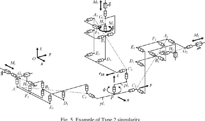
2. Type 2 singularities.
Type 2 singularities [21] of the mechanism are also quite simple to analyze. They appear when = 3
+ /2. In such a case, the wrench r33 is directed along the direction of the platform pl2 (Fig. 5). This is
the reason why, when moving actuator M4, rotations of the platform around the vertical axis are
impossible. On the other hand, fixing the position of actuator M4, the platform can encounter a small
rotation around point P.
Introducing = 3 + /2 into Eq. (18) leads to:
y x r
x
y G G
sin cos sin cos
0 3 3 . (24)
Thus, fixing the orientation of the platform, for any altitude z, the singularity loci are defined by a straight line in the horizontal plane Oxy (or a vertical plane in 3D).
Fig. 5. Example of Type 2 singularity.
3. Constraint singularities.
Other cases of singularities appear if the system of wrenches applied on the platform degenerates. The degeneracy of the system of wrenches can be analyzed using the Newton-Euler theorem.
Figure 6 represents the forces applied to the platform by the legs. Let us suppose that a wrench f is applied on the platform pl2 at point P. Let us also denote by p = [p1, p2, p3, p4, p5, 0]T the reaction
wrench at the passive revolute joint of the platform. So the following relations can be written: 0 r r r p f f13 13 f23 23 f33 33 , (25a) 0 r r r r p 11 12 21 22 f11 f12 f21 f22 . (25b)
Fig. 6. Constraints applied to the platform of the Pantopteron-4.
Rewriting this system of equations into matrix form yields:
T
T
T f f f f f f f p p p p p f 01 6 M 1 2 3 4 5 11 21 12 22 13 23 33 , (26) where
1 6 1 6 1 6 22 12 21 11 5 1 5 5 33 23 13 1 6 1 6 1 6 1 6 5 1 5 5 0 0 0 r r r r 0 I r r r 0 0 0 0 0 I M T T . (27)Thus, there are constraint singularities if matrix M degenerates, i.e., if:
cos cos cos sin sin sin
0cos )
det(M r 3 1 2 3 1 2 3 , (28)
For ≠ 3 + /2, the mechanism is in a constraint singularity if and only if:
0 sin sin sin cos cos cos 1 2 3 1 2 3 h (29)
In such a case, the three moments r1i applied to the platform are linearly dependant, i.e., their axes are
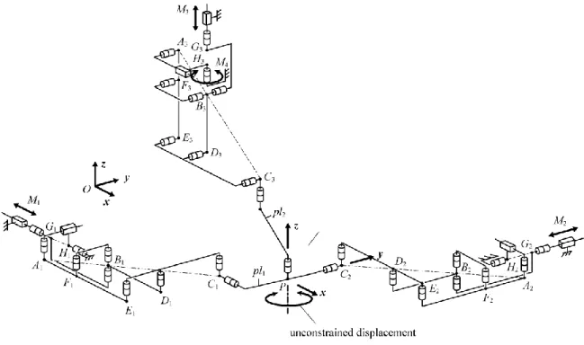
parallel or coplanar. Thus, the platform becomes unconstrained and it gains one supplementary DOF. Let us study the example presented on Fig. 7. Axis a11 is parallel to the y axis and axes a12 and a13 are
parallel to the x axis. Thus, the DOF gained by the platform is a rotation about an axis parallel to the z axis.
Fig. 7. Example of a constraint singularity.
Expressing Eq. (29) in the Cartesian space yields:
0 ) ( ) ( ) ( ) ( ) ( ) ( 3 2 1 3 3 2 2 1 1 3 2 1 3 3 2 2 1 1 yC yG zC zG xC xG zC zG xC xG yC yG h (30) where 2 1 1 2 1 1 1 (yC yG ) (zC zG ) , (31a) 2 2 2 2 2 2 2 (zC zG ) (xC xG ) , (31b) 2 3 3 2 3 3 3 (xC xG ) (yC yG ) . (31c)
In these expressions, xCi, yCi, zCi, xGi, yGi, zGi correspond to the coordinates of points Ci and Gi about the
x, y and z axes, respectively. Disregarding the case where i tends to infinity, singularities appear when: 0 ) ( ) ( ) ( ) ( ) ( ) (yC1yG1 zC2 zG2 xC3xG3 zC1zG1 xC2 xG2 yC3 yG3 (32) Taking into account that the terms xGi, yGi, zGi appearing in (32) are constant and that
T i i i T i [x,y,z] [a ,b ,c ] OC (33)
where ai, bi, ci are either constants (for i = 1, 2) or variables depending on angle , for i = 3.
Equation (32) can be rewritten under the form:
0 8 7 6 5 4 3 2 1 xyz p xy p xz p yz p x p y p z p p (34)
where coefficients pi are terms depending on the angle , the position of points Gi and of the shape of the
platform. Fixing the altitude z of the platform, Eq. (34) is the expression of a hyperbola, of which the coefficients depend on the altitude of the platform, on its orientation and on the geometric parameters of the mechanism.
Thus, contrary to the Isoglide4 or the Quadrupteron, our mechanism has constraints singularities. This is due to the fact that some legs of the Isoglide4 or of the Quadrupteron are attached to the platform by a revolute joint, instead of a Cardan joint, which overconstrains the displacement of the platform and allows avoiding such singular configurations. However, it will be shown in the following section that,
even if the Pantopteron-4 has singularities, they can be easily removed from its workspace.
III. DESIGNCONSIDERATIONS
In this part, we will perform the analysis of the workspace of the mechanism, taking into account the geometric limitations and singular configurations, and discuss some other possible architectures based on this mechanism.
A. Geometric workspace analysis
Many parameters influence the size of the workspace of the Pantopteron-4. Among the main parameters, we can mention:
- the lengths of the links of the pantograph;
- on the locations of the axes of the base-mounted revolute joints; - the shape of the platform;
- the maximal stroke of the actuators and of the passive linear guide; - the interference between the links.
Using a geometrical approach, we will compute the workspace of the Pantopteron-4. As the Pantopteron-4 is a 3T1R parallel mechanism, its workspace for a given orientation of the platform can be found as the intersection of three so-called vertex spaces.
Analyzing the vertex space of the leg i, it only depends on: - the lengths of the links of the pantograph;
- the maximal and minimal strokes of the actuators and of the passive linear guide; - the interferences between the links;
- the singular configurations.
In a first step, let us concentrate on the boundaries of the workspace due to the interference of the links and of the singular configurations. As mentioned previously, for a leg, there are two types of singularities:
a. when the parallelogram BiDiEiFi degenerates into a line; such a singularity can be avoided by
limiting the angle i between the links (AiEi) and (EiCi) of the parallelogram, which, in the same
time, allows limiting some inferences between the links. The maximal and minimal angles will be denoted (i)max and (i)min, respectively.
b. when points Ai, Bi and Ci are aligned along the same axis; such a case can easily be avoided by
limiting the stroke of the passive prismatic joint 9i. This minimal stroke will be denoted (si)min.
To avoid interference between the links and the base, a maximal stroke of the actuator has to be fixed at (i)max.
Each leg is mounted in rotation around one axis parallel to a3i. Thus, the problem of finding the vertex
space can be limited to a planar analysis of the minimal and maximal displacements of point Ci, the
Considering case (a), we have to find the boundaries of the leg when angle i is fixed. Fixing angle i
is equivalent to fixing the lengths of segments (AiBi) and (AiCi). These lengths are equal to:
i EiCi AiEi AiEi EiCi AiCi l l l l l 2 2 2 cos (35) k l lAiBi AiCi/ (36)
Fig. 8. Displacement of Ci when i is fixed.
Displacing the prismatic guides, segments (AiBi) and (BiCi) describe Cardanic motions [23]-[24]. As a
result, for a given angle i, the displacement locus of point Ci is an ellipse E (Fig. 8). Thus, considering
the extremes (i)max and (i)min of angle i, the boundaries of the workspace are given by the ellipses
(a) planar projection of the vertex space. (b) the 3D vertex space of the leg.
(c) the 3D useful vertex space of the leg.
Fig. 9. Schematics of the vertex space of a leg from the Pantopteron-4.
Cases (b) and (c) are much simpler to analyze. The displacement of point Ci when the passive guide
(9i) is at its minimal stroke (si)min is a vertical line L1 located at (k–1) times the distance (si)min from the
vertical axis (GiBi) (Fig. 9(a)). The displacement of point Ci when the actuator Mi is at its maximal
stroke (i)max is a horizontal line L2 located at k times the distance between the maximal position of point
Bi and the position of point Ai along the axis a3i, from the axis of the horizontal passive joint 9i
The entire vertex space is represented at Fig. 9(b). On all of these figures, two boundaries due to two constraints, which are the maximal strokes of the actuated and passive linear joints, are not represented. These boundaries are vertical and horizontal straight lines. However, in a first step, it is preferable to have the largest vertex space for the legs and, thus, to remove these two boundaries from our workspace by a proper selection of the stroke of the linear guides.
We can implement in Matlab our geometric method in order to be able to optimize the workspace of the Pantopteron-4 by minimizing the lengths of the pantograph’s links in each leg. This could be done more promptly in a commercial CAD system, such as CATIA [25]. Figure 10(a) shows an example of the workspace of a Pantopteron-4 with relatively short legs. We can obtain the best ratio between the lengths of the links and the volume of the workspace. A relatively large increase of the link lengths will result in only a negligible gain in the workspace volume.
(a) with relatively short legs. (b) with relatively long legs.
Fig. 10. Orientation workspace of the Pantopteron-4.
However, it would obviously be a mistake to design a 3T1R parallel mechanism with such a complex workspace. Thus, our decision is to keep the links as long as it takes, so that the workspace of the mechanism becomes a simple geometric form, namely a rectangular parallelepiped. In other words, the workspace of a Pantopteron-4 with sufficiently long legs has to become a box whose sides are of length
ki (i being the stroke of actuator Mi, i = 1, 2, 3), as shown in Fig. 10(b) (see the example in the next
section).
In order to obtain such a simple volume, when the three vertex spaces are intersected, it is the planar caps that limit the workspace and not the other surfaces. Of course, we still try to minimize the length of the links, by carefully locating the prismatic actuators on the base and properly choosing the dimensions of the mobile platform and of the stroke of the actuators. Furthermore, if the workspace of the mechanism has to be a parallelepiped, the shape of the vertex space should not be too complicated, and can be reduced to a hollow cylinder (Fig. 9(c)). This can be accomplished by properly constraining the maximal stroke of the active and passive linear guides in order to obtain, in the planar projection of the workspace, a rectangle denoted as the useful vertex space (two possible examples of the useful vertex space are presented in Fig. 9(a)).
The workspace volume of the Pantopteron-4 is the other main advantage of the proposed robot. Indeed, the maximal volume of the workspace of the Quadrupteron or Isoglide4 is V = 123 while
that of the Pantopteron-4 is V = k3123, i.e., for the same set of given actuators, the workspace of
the Pantopteron-4 is k3 times bigger than that of the other robots.
Moreover, it is well known that the actuators represent a major portion of the cost of a robot. For creating a fast mechanism with actuated prismatic joint, it is preferable to use linear motors that reach higher velocities. However, the main drawback of such actuators is their price, which is directly proportional to the length of their stroke. For a given maximal workspace, the stroke of the actuators of the Quadrupteron or Isoglide4 is k times greater than that of the motors of the Pantopteron-4. Therefore, even if the Pantopteron-4 is more complicated to design than a Quadrupteron or an Isoglide4, its manufacturing cost would likely be lower.
B. Singularity-free workspace
It is impossible to speak about the workspace of a parallel mechanism without dealing with singularities. As observed from Eq. (34), the constraint singularities depend on the position of the mobile platform, on the locations of the axes of the base-mounted revolute joints, and on the shape of the platform. Thus, analyzing Eq. (34), there are nine design parameters which are yG1, zG1, xG2, zG2, xG3, yG3, a1, b2, and c3 (we do not consider the lengths of the links of the pantograph linkages as they do not
influence these singular configurations). So, there are too many parameters for a complete analysis of the singular configurations. Therefore, we will restrict our analysis to some particular designs.
We will consider in this part a mechanism which has a platform with two concurrent axes (for example the ones of joints 12,1 and 12,2), and a base whose three pantograph axes of rotations are also concurrent. Therefore, considering that the intersection point of the pantograph axes is the origin of the base frame, and that point P is at the intersection of the two axes of the platform, only c3 (= r) stay
variable, the other ten parameters being equal to zero. In such a case, Eq. (34) becomes:
2xyyrcosxrsin
0z (37)
Thus, singular configurations will appear if the platform of the mechanism is located in the plane P1 (z
= 0), or if it is located on a hyperbola H whose expression is:
0 sin cos
2xyyr xr (37)
Please note that this expression does not depend on the altitude z of the platform. It is well known that such a hyperbola has two asymptotes,
2 / ) cos (r x (39) 2 / ) sin (r y (40)
which, in 3D, represent two planes which we will denote by P2() and P3(). These planes, projected in
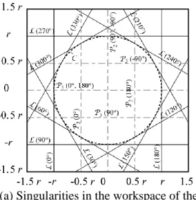
Let us now take into account the Type 2 singular configurations. These singularities are described by Eq. (24) and are represented on Fig. 11a by the lines denoted L(). It is also possible to represent the curve tangent to all these lines, which represents the workspace without Type 2 singular configurations: it is the circle C of radius r, centred in O.
(a) Singularities in the workspace of the Pantopteron-4 for any angle (planar projection)
(b) Singularities in the workspace of the Pantopteron-4 for [0, 90°] (3D).
Fig. 11. Singularity free workspaces.
Fig. 12. Amplification device for the rotation of the platform.
Thus, for any angle , the singularity-free workspace does not exist. This is due to the fact that, if we represent the all planes P2() and P3() and all lines L() for any angle between 0° and 360° on the
same figure, the entire workspace will be filled with singularities. However, this major drawback can be easily suppressed by limiting the possible rotation of the platform in an interval of 90°. The workspace with the boundaries of the singularity loci for [0, 90°] is represented on Fig. 11b. It is clear on this picture that the regions IV and VIII are completely free of singular configurations. Obviously, several applications need a rotation superior to 90°. However, such a drawback can be compensated by using an amplification device, such as the one presented on Fig. 12, in order to transform the limited rotation of the platform into large rotations of the end-effector. This system is composed of two gears, one fixed on the rotating link pl2 of the platform, the other on the orientation-fixed part pl1. The manipulated device
will be located on the smallest gear that will permit the amplification of the rotation of the link pl2. A
pulley belt mechanism may also be used instead of gears.
A possible version of a prototype of a Pantopteron-4 is represented at Fig. 13. Its geometric parameters are:
- lAiEi = 0.2 m, lEiCi = 0.3 m, k = 3;
- yG1 = zG1 = xG2 = zG2 = xG3 = yG3 = 0 m, a1 = b2 = 0 m, r = 0.05 m;
- actuator strokes = 0.06 m ((zi)min = -0.22 m, (zi)max = -0.16 m)
- passive linear guide strokes = 0.14 m ((si)min = 0.01 m, (si)max = 0.15 m) ;
- (i)min = 25°, (i)max = 155°.
Its design is achieved such that its workspace is a cube whose side is equal to 0.18 m for any value of angle [0, 90°].
Fig. 13. CAD model of a possible prototype of Pantopteron-4.
C. Other possible architectures
Finally, we would like to mention that the design of the Pantopteron-4 presented here is not the only solution for creating such a mechanism. First, as the leg is made up of a pantograph linkage, several designs are possible, which are presented in [26]. However, we believe that the architecture we proposed is the most practical one. Moreover, note that the planar RP chain composed of the revolute joint 10i and the prismatic joint 9i may be removed and replaced by any kinematic chain able to perform a planar displacement, such as planar RRR, RPR, PPR or PRR chains (Fig. 14). Using such chains, points Hi and Gi need not be aligned. However, such changes in the design will lead to different singular
(a) the RP chain is replaced by a RPR chain. (b) the RP chain is replaced by a RRR chain.
(c) the RP chain is replaced by a PRR chain. (d) the RP chain is replaced by a PPR chain.
IV. CONCLUSIONS
In this paper, a novel 4-DOF decoupled 3T1R parallel mechanism, named the Pantopteron-4, was presented. The Pantopteron-4 end-effector displaces k times faster than its linear motors (k being the magnification factor of the pantograph linkages). Moreover, for a given set of actuators, its workspace is
k3 times bigger than the stroke of its actuators. Though the mechanism proposed has several singular configurations, it is easy to choose proper design parameters that lead to a large singularity-free workspace. This novel mechanism is foreseen to be used in applications where the velocities and accelerations have to be high, such as in pick-and-place.
V. REFERENCES
[1] C.M. Gosselin, X. Kong, Cartesian Parallel Manipulators. US patent 6,729,202, filed July 8, 2002, and issued May 4, 2004.
[2] M. Carricato, V. Parenti-Castelli, Singularity-Free Fully-Isotropic Translational Parallel Manipulators. The International Journal of Robotics Research 21 (2) (2002) 161–174.
[3] X. Kong, C.M. Gosselin, Type Synthesis of Linear Translational Parallel Manipulators. Advances
in Robot Kinematics: Theory and Applications. J. Lenarcic, F. Thomas, eds., Kluwer Academic
Publishers, 2002, pp. 453–462.
[4] X. Kong, C.M. Gosselin, A Class of 3-DOF Translational Parallel Manipulators with Linear Input-Output Equations. Proceedings of the Workshop on Fundamental Issues and Future Research
Directions for Parallel Mechanisms and Manipulators, Quebec City, Quebec, Canada, October 3–
4, 2002, pp. 25–32.
[5] C.-C. Lee and J-M. Hervé, Cartesian Parallel Manipulators with Pseudoplanar Limbs, ASME Journal of Mechanical Design, 129 (12) (2007), 1256-1264.
[6] H.S. Kim, L. W. Tsai, Evaluation of a Cartesian Parallel Manipulator. Advances in Robot
Kinematics: Theory and Applications, J. Lenarcic, F. Thomas, eds., Kluwer Academic Publishers,
2002, pp. 21–28.
[7] G. Gogu, Structural Synthesis of Parallel Robots, Part 1 – Methodology. Springer, the Netherlands, 2008.
[8] J-M. Hervé, The Lie Group of Rigid Body Displacements, a Fundamental Tool for Mechanism Design, Mechanism and Machine Theory, 34 (5) (1999), 719-730,
[9] G. Gogu, Singularity-Free Fully-Isotropic Parallel Manipulators with Schoenflies Motions.
Proceedings of the 2005 IEEE 12-th IEEE International Conference on Advanced Robotics (ICAR 2005), Seattle, WA, USA, July 18-20, 2005, pp. 194-201.
[10] G. Gogu, Fully-Isotropic Parallel Manipulators with Schoenflies Motions and Complex Legs with Rhombus Loops. Proceedings of the 2006 IEEE International Conference on Robotics and
Automation (ICRA), Orlando, Florida, USA, May, 2006, pp. 1147-1152.
[11] G. Gogu, Structural Synthesis of Fully-Isotropic Parallel Robots with Schoenflies Motions via Theory of Linear Transformations and Evolutionary Morphology. European Journal of Mechanics
/ A –Solids 26 (2) (2007) 242-269.
[12] C.M. Gosselin, M. Tale Masouleh, V. Duchaine, P.-L. Richard, S. Foucault, X. Kong, Parallel Mechanisms of the Multipteron Family: Kinematic Architectures and Benchmarking. Proceedings
of the 2007 IEEE International Conference on Robotics and Automation (ICRA), April 10-14,
2007, Rome, Italy.
[13] B.C. Bouzgarrou, J.-C. Fauroux, G. Gogu, Y. Heerah, Rigidity analysis of T3R1 parallel robot with uncoupled kinematics. Proceedings of the 35th International Symposium on Robotics (ISR), Paris, France, March 23-26, 2004.
[14] I.A. Bonev, Delta Robot — the Story of Success. On-line article available at www.parallemic.org/Reviews/Review002.html, 2001.
[15] F. Pierrot, V. Nabat, O. Company, S. Krut., P. Poignet, Optimal Design of a 4-dof Parallel Manipulator: From Academia to Industry. IEEE Transactions on Robotics, 25 (2) (2009)213-224. [16] S. Briot, V. Arakelian, S. Guégan, PAMINSA: a New Family of Decoupled Parallel Manipulators.
Mechanism and Machine Theory, 44 (2) (2009) 425-444.
[17] S.-M. Song and J.-K. Lee, The mechanical efficiency and kinematics of pantograph type manipulators, Proceedings of the IEEE International Conference on Robotics and Automation (ICRA 1988), Philadelphia, Pennsylvania, USA, April 24-29, 1988, Vol.1, pp. 414-420.
[18] S. Briot, I.A. Bonev, Pantopteron: a New Fully-Decoupled 3-DOF Translational Parallel Robot for Pick-and-Place Applications. ASME Journal of Mechanisms and Robotics, 1 (2) (2009).
[19] S. Briot, V. Arakelian, S. Guégan, Design and Prototyping of a Partially Decoupled 4-DOF 3T1R Parallel Manipulator with High-Load Carrying Capacity. Journal of Mechanical Design, 130 (12) (2008).
[20] C.-C. Lee and J-M. Hervé, Cartesian Parallel Manipulators with Pseudoplanar Limbs, ASME Journal of Mechanical Design, 129 (12) (2007), 1256-1264.
[21] C.M. Gosselin, J. Angeles, Singularity analysis of closed-loop kinematic chains. IEEE
Transactions on Robotics and Automatics, 6 (3) (1990) 281-290.
[22] D. Zlatanov, I.A. Bonev, C.M. Gosselin, Constraint Singularities of Parallel Mechanisms,” IEEE
International Conference on Robotics and Automation (ICRA 2002), Washington, D.C., USA, May
11–15, 2002.
[23] A. Sekulie, Method of Synthesis of Cardanic Motion,” Facta Universitatis, Mechanical Engineering, University of NIS, 1 (5) (1998) 565–572.
[24] C.R. Tischler, K.H. Hunt, A.E. Samuel, A Spatial Extension of Cardanic Movement: Its Geometry and Some Derived Mechanisms. Mechanism and Machine Theory, 33 (8) (1998) 1249–1276. [25] I.A. Bonev, J. Ryu, A Geometrical Method for Computing the Constant-Orientation Workspace of
[26] D.-M. Lu, W.-M. Hwang, Synthesis of Planar Five-Bar Pantograph Configurations by a Geometric Method”, Mechanism and Machine Theory, 31 (1) (1996) 11–21.