Science Arts & Métiers (SAM)
is an open access repository that collects the work of Arts et Métiers Institute of Technology researchers and makes it freely available over the web where possible.
This is an author-deposited version published in: https://sam.ensam.eu
Handle ID: .http://hdl.handle.net/10985/8527
To cite this version :
S. MEZLINI, S MZALI, S SGHAIER, Chedly BRAHAM, Philippe KAPSA - Effect of a combined machining/burnishing tool on the roughness and mechanical properties Lubrication Science -Vol. 26, p.175–187 - 2014
Any correspondence concerning this service should be sent to the repository Administrator : archiveouverte@ensam.eu
Effect of a combined machining/burnishing tool on the roughness
and mechanical properties
S. Mezlini
1,*
,†, S. Mzali
1, S. Sghaier
1, C. Braham
2and Ph. Kapsa
31
Laboratoire de Génie Mécanique, Ecole Nationale d'Ingénieurs de Monastir, Avenue Ibn El Jazzar, University of Monastir, 5019, Monastir, Tunisie
2
CNRS UMR 8006, Ecole Nationale Supérieure, LIM, d'Arts et Métiers, 151 Bd de l'Hôpital, 75013 Paris, France
3Ecole Centrale de Lyon, Laboratoire de Tribologie et Dynamique des Systemes, UMR CNRS 5513, 36 avenue Guy de
Collongue, Ecully Cedex 69134, France
ABSTRACT
Burnishing is a cold working surface treatment process in which plastic deformation of surface irregularities occurs by exerting pressure through a very hard and a very smooth roller or ball on a surface to generate a uniform and work-hardened surface. This treatment occurs generally after the machining process. In this study, a new combined machining/burnishing tool is designed and is fabricated. This tool allows for generating simultaneously the machining (turning) and the burnishing of the cylindrical surface using a turning machine.
First, turned surfaces at different conditions, sketches, finishing and half finishing were performed using only the cutting tool. The evolutions of a surface roughness parameter and the technological time relative to every test condition have been investigated. Second, using the combined machining/burnishing tool at coarse conditions, the evolutions of the surface roughness and the technological time have been also inves-tigated. A comparison among the parameters obtained under different machining conditions and those obtained using the combined machining/burnishing tool has been carried out. Moreover, the analyses of the layers obtained on the combined machined/burnished surface have shown that the burnishing process induces compressive residual stresses on the subsurface treated specimens.
INTRODUCTION
In order to obtain a satisfactory surface quality, many efforts are mainly oriented to the improvement of the cutting tool performance and to the plastic deformation of the machined materials. It is known that the conventional machining methods, such as turning and milling, leave inherent irregularities on the surface, and it hence the need to realise a series of costlyfinish operations.1,2The technical progress
*Correspondence to: S. Mezlini, Laboratoire de Génie Mécanique, Ecole Nationale d'Ingénieurs de Monastir, Avenue Ibn El Jazzar, 5019 Monastir, Tunisie.
has developed the use of very hard materials in several fields such as manufacturing parts for the aeronautic and the mechanical industries.3,4
The metallic surface characteristics can be improved by applying mechanical treatments as roller,5,6 multi roller7or ball8burnishing, which modify the superficial layer properties in terms of hardness and roughness.9As the superficial layers are loaded in service, they will be the first to be degraded by wear following the various contacts with the other parts and the influences of the surrounding en-vironment. Both the roller and the ball burnishing processes implement a plastic cold working of the superficial layer and act on their geometrical and physical properties as well.
In general, the parameters affecting the plastic deformation process are variable, and they can be rep-resented by the burnishing speed, the burnishing feed, the ball or the roller diameter, the burnishing force as well as the number of burnishing tool passes.10–15The burnishing force is one of the most im-portant parameters in the burnishing process. A larger force induces an increase in hardness, although a very important strength generates an increase in roughness.16
It is clear, however, that other parameters contribute to thefinal properties of the part surface, namely, the penetration depth and the initial state of the surface quality.17El-Axir et al.18had demonstrated that the workpiece initial hardness controls the effect of the other parameters on each response.
El-Taweel et al.19had found that the effect of the burnishing force is the dominant effect on surface roughness and microhardness, followed by the burnishing feed, burnishing speed and the number of burnishing tool passes. They have shown that the microhardness best improvement is obtained at the lowest burnishing speed, the highest burnishing force and the highest number of burnishing tool passes. As indicated by H. Hamadache et al.,20the number of burnishing tool passes should be limited to two in order to have the best roughness, whereas three passes were recommended to have the highest hardness.
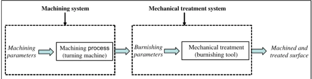
Actually, the mechanical treatment has been often applied after the machining process (Figure 1). The objective of this study is to develop a new device that allows for combining the machining and the burnishing processes (Figure 2). Using this new device, three types of parameters were distin-guished: machining parameters, burnishing parameters and common parameters. These last parameters that are the same for both machining and burnishing are rotational speed and feed rate.
In fact, by using the combined machining and burnishing system, some parameters relative to the machining and burnishing process became dependent (common parameters). Particularly, the two pro-cesses have the same speed and the same feed rate. However, other parameters have remained indepen-dent and always relative to the burnishing and the machining processes such as the burnishing force and the ball dimension and the penetration depth, respectively.
This study describes a new device for a combined machining and mechanical plastic deformation. The influence of the test parameters on C45 (2MTI, Metals, Materials and industrial technique, Sousse,
Machining parameters Machining process (turning machine) Burnishing parameters Mechanical treatment (burnishing tool) Machined and treated surface
Machining system Mechanical treatment system
Tunisia) steel behaviour has been developed. After turning at different conditions, sketches,finishing and halffinishing, the evolution of surface roughness and technological time has been investigated. Comparison between surface roughness using the combined machining/burnishing tool and consider-ing the same sketchconsider-ing conditions and those obtained by machinconsider-ing at different conditions, namely, sketching,finishing and half finishing, has been conducted. The residual stress through a cross section of the machined and the combined machined/burnished surfaces has been also investigated.
EXPERIMENTAL DETAILS Material specification and specimen preparation
In this study, C45 steel chemical composition 0.45–0.48% C, 98% Fe, 0.6–0.9% Mn was used. Yield strength (Re) and ultimate strength (Rr) were, respectively, 530 and 625 MPa, whereas elongation at break (A%) reached 12%. The workpieces were received in the form of a cylindrical rod and were ini-tially turned into a circular form of 30 mm diameter.
Combined machining/burnishing tool
A combined turning/burnishing tool (Figure 3) with interchangeable adapter for ball was designed and was fabricated. This tool allows for simultaneously machining and burnishing a cylindrical workpiece using a turning machine. The combined tool is constituted then of carbide cutting tool and 100Cr6 burnishing ball tool (BOUDRANT, Tunis, Tunisia.). The device has the advantage of being simple to assemble on a universal lathe as shown in Figure 3 and most importantly obtaining a machined and burnished surface in one step.
A schematic representation of the support is shown in Figure 3b. The support is installed on the lathe, and the two tools are mounted on it.
The ball burnishing tool was used with a pre-calibrated spring to measure the burnishing force (Figure 4) and then to calculate the normalised mean contact pressure. In this tool, a disposable 100Cr6 steel ball of 12 mm diameter was used. The hardness of the ball burnishing and its roughness are about 63 Rockwell Hardness (HRC) and 0.05μm, respectively. The ball burnishing is in contact with 4 balls, which allows for minimising the friction coefficient. A calibration process was conducted using the actual burnishing operation setting to obtain a relationship between the contact pressure and the corresponding axial displacement.
Test parameters
Initially, the turned surfaces at different conditions, sketches, finishing and half finishing were performed using only the cutting tool. The evolutions of surface roughness parameter and the techno-logical time relative to every condition were investigated. Table I shows the turning conditions relative to sketched,finished and half-finished surfaces.
In order to put forward the usefulness of the combined tool previously described, the specimens were simultaneously machined and burnished. The cutting conditions, namely, cutting velocity, feed rate and penetration depth, were similar to those used in sketched tuning. However, the normalised mean contact pressure was varied: 2.94, 3.71, 4.24, 4.67 and 5.07.
(a)
(b) workpiece
Burnishing tool
Cutting tool
Figure 3. (a) Combined turning/burnishing device mounted on a parallel lathe and (b) schematic repre-sentation of the support.
The surface topography and the technological time relative to the machined surface at different cut-ting conditions were compared with the ones obtained using the combined machining/burnishing tool. In order to characterise the transformed layer, the subsurface residual stress and the microhardness were measured on the cross section for the machined and combined machined/burnished surfaces at different conditions.
RESULTS AND DISCUSSION Microscopic analyses
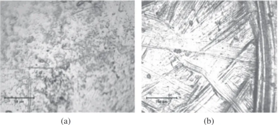
Scanning electron microscope micrographs of non-treated and combined turned and burnished surfaces are shown in Figure 5. The presence of abrasion grooves and wear debris was observed on the non-treated surfaces (Figure 5a). These grooves were generated during the cutting process. In con-trast, the presence of grooves was attenuated for combined turned and burnished surfaces (Figures 5b and 5c). Moreover, scanning electron micrographs show the presence of delamination phenomena for the combined turned and burnished surfaces with normalised mean contact pressure of 5.03.
Ball burnishing Calibrating spring Lives pressure
Support balls
Figure 4. Schematic representation of ball burnishing tool.
Table I. Turning conditions.
Turning conditions
Parameters vc(m/min) Feed rate (mm/tr) Depth penetration (mm)
Sketches 113 0.3 2
Halffinishing 148 0.2 1
Figure 6 shows the micrographic appearance of the balls before and after burnishing using normalised mean contact pressure of 5.03. After burnishing, the ball surface presented grooves with no preferred directions. They were principally due to the interaction between the burnishing ball, the burnished surface and wear debris.
Roughness
To quantify the variation of the surface topography, roughness profiles obtained under different con-ditions were measured. After each test, the topographic parameters were measured and the technolog-ical time was deduced. For each test,five profiles were also performed using a tactile profilometer, and an average of arithmetic roughness is calculated. However, the technological time was calculated for the same bearing length of 20 mm.
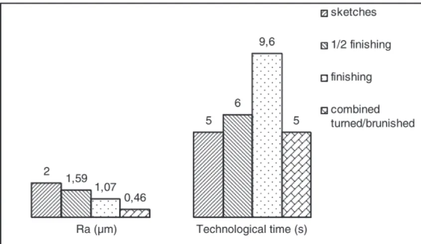
Figure 7 shows the different parameters relative to the different cutting conditions. It shows that the surface roughness depends on the cutting conditions. Thus, the lowest arithmetic surface roughness (Ra) is obtained when using thefinishing conditions. However, the highest Rais obtained by using
(a) (b) (c)
delamination
Figure 5. Scanning electron microscope micrographs of surfaces: (a) non-treated, (b) normalised mean contact pressure 3.71 and (c) normalised mean contact pressure 5.03.
(a) (b)
Figure 6. Scanning electron microscope micrographs of ball surface: (a) before burnishing, (b) after bur-nishing (Normalised mean contact pressure 5.03).
the sketched conditions. The technological time varies also by using different cutting conditions and increases when Radecreases.
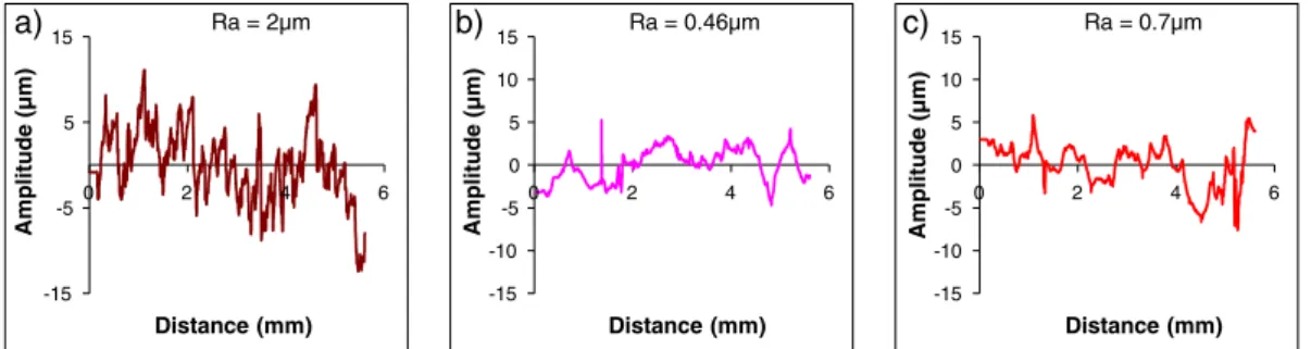
Figure 8 shows three profiles for a turned surface at coarse conditions and combined turned and burnished surfaces with 3.71 and 4.67 normalised mean contact pressure. It shows the improvement of topographic properties when the burnishing process has been applied.
In order to better analyse the effect of the burnishing process, the evolution of Ra versus the normalised mean contact pressure has been investigated. Figure 9 shows the evolution of Raversus the normalised mean contact pressure obtained by the new device. It shows that Radecreases from 2 μm relative to the non-treated surface to 0.5 μm for the burnished surface. It shows also that for a normalised mean contact pressure lower than 3.71, Radecreases when the normalised mean contact pressure increases. However, for a normalised mean contact pressure more than 4.24, the effect of the burnishing surface on Rais not significant. In this case, the surface topography degrades, and the surface roughness slowly increases.
Hokkirigawa and Kato21,22had emphasised the evolution of the plastic deformation modes of metals depending on the degree of penetration. In fact, when a medium contact pressure is applied, a cold plastic
2 5 1,59 6 1,07 9,6 Ra (µm) Technological time (s) sketches 1/2 finishing finishing
Figure 7. Evolution of technological time and surface roughness at different cutting conditions.
-15 -5 5 15 0 2 4 6 Amplitude (µm) Distance (mm) a) Ra = 2µm -15 -10 -5 0 5 10 15 0 2 4 6 Amplitude (µm) Distance (mm) -15 -10 -5 0 5 10 15 0 2 4 6 Amplitude (µm) Distance (mm) b) Ra = 0.46µm c) Ra = 0.7µm
Figure 8. Effect of burnishing process on roughness profile: (a) sketched, (b) normalised mean contact pressure 3.71 and (c) normalised mean contact pressure 4.67.
deformation of the superficial layers occurs. The ploughing deformation takes place without any material debris. The peak asperities areflattened and fill the hollow furrows leading to a surface smoothing out. A polished surface is obtained, and an improvement on the surface roughness is shown. Increasing the con-tact pressure modifies the wear mode. The wedge forming mode appears. Besides, at high contact pres-sure, the plastic deformation increases and induces high work-hardening into the surface causing surface chipping and delamination. When surface deterioration occurs, the surface roughness increases.
The micrographs previously illustrated (Figures 5 and 6) show that the turned surface presents grooves. However, the ball before burnishing shows a smooth surface with low roughness of 0.05μm. In fact, burnishing and especially with large normalised mean pressure can degrade the ball surface and increases so its roughness. These degradations can be caused by the presence of work-hardened wear debris generated during burnishing process and present at the interface.
Figure 10 presents the technological time and Raobtained by machining at different conditions and those obtained using the combined tool for a normalised mean contact pressure of 3.71. It shows that
0 0.5 1 1.5 2 2.5 0 1 2 3 4 5 6 Surfac e roughnes s Ra (µm) Pm/ y
Figure 9. Evolution of arithmetic surface roughness versus the normalised mean contact pressure.
2 5 1,59 6 1,07 9,6 0,46 5 Ra (µm) Technological time (s) sketches 1/2 finishing finishing combined turned/brunished
Figure 10. Evolution of technological time and surface roughness at different cutting conditions using the combined machining/burnishing tool.
by using the combined tool at the sketched conditions, the surface roughness can be less than the one obtained with thefinishing conditions. Thus, the combined tool allows on the one hand, to reduce the technological time from 9.6 using the finishing condition to 5 s with coarse conditions, and on the other hand, to obtain a surface roughness less than the one obtained with thefinishing conditions. Residual stresses and microhardness
After the burnishing process, residual stress in the surface was also analysed. The measurement was obtained using a Proto-iXRD machine (stress measurement system) (Ecole Nationale Supérieure, LIM, d'Arts et Métiers, Paris, France).
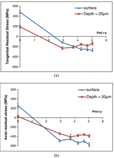
Figures 11a and 11b show respectively the evolution of tangential and axial residual stresses versus the normalised mean contact pressure. The residual stresses were measured at the treated surface and at a depth of 20μm below. (a) (b) -600 -400 -200 0 200 400 600 0 1 2 3 4 5 6
Tangential Residual Stress (MPa)
Pm/ y surface Depth = 20µm -600 -400 -200 0 200 400 600 0 1 2 3 4 5 6
Axial residual stress (MPa)
Pm/ y surface Depth = 20µm
Figure 11. Evolution of residual stress versus the normalised mean contact pressure using the combined machining/burnishing tool: (a) tangential residual stress and (b) axial residual stress.
For the sketched and non-treated surface, Figure 11 shows that the residual stresses are positive both at the surface and at a depth of 20μm. During a machining operation, the upper layer is plastically de-formed then undergoes a tensile load. Therefore, tensile stresses are induced into a surface. In addition, the increasing of the cutting temperature promotes more tensile residual stresses.23 The residual stresses on the surface are more important than those measured at a depth of 20μm.
However, by using the combined machining/burnishing tool, the residual stresses become negative at the surface and at a depth of 20μm. In fact, the surface undergoes a compressive load that induces a compressive residual stress.24Moreover, increasing the normalised mean contact pressure decreases the tangential residual stresses in the surface from 100 (for Pm/σy = 2.94) to 270 MPa (for Pm/σy = 5.03). At 20 μm below the surface, the tangential residual stresses slightly increase from
230 (for Pm/σy = 2.94) to 140 MPa (for Pm/σy = 5.03) (Figure 11).
Figure 11b shows that the axial residual stresses are greater than the tangential ones. It also shows that the residual stresses in the surface are more important than those measured at 20 μm below it. The normalised mean contact pressure effect on the axial residual stresses is not significant for the normalised mean contact pressure varied from 2.94 to 5.03. The average of the axial residual stresses induced by using the combined tool is about 510 at the surface and 380 MPa at 20μm below the surface.
The residual stresses below the machined and combined machined/treated surfaces were investi-gated using cross sections. Figure 12 shows the evolution of the residual stresses versus the depth be-low the machined and combined machined/treated surfaces obtained using the combined tool for a normalised mean contact pressure of 5.03. It shows that for the machined surfaces, the residual stresses are positive for a depth less than 20μm. These stresses become compressive for a depth of 50, 100 and 150μm.
However, the analysis of the residual stresses relative to combined machined/treated surface show that the residual stresses are compressive for a depth from 0 to 250μm. The maximum residual stress is obtained at the surface. Both the surface roughness and the residual stresses curve versus normalised mean contact pressure show the same evolution. In fact, for a low normalised mean contact pressure, it is first noted that both the surface roughness and the residual stresses decrease. Second, for high normalised mean contact pressure, both the surface roughness and the residual stresses remain almost constant. The combined machining/burnishing process leads to a transition from residual tensile to re-sidual compressive stresses. These compressive stresses induced by the combined tool can improve then the fatigue strength and tribological behaviour of the treated parts.
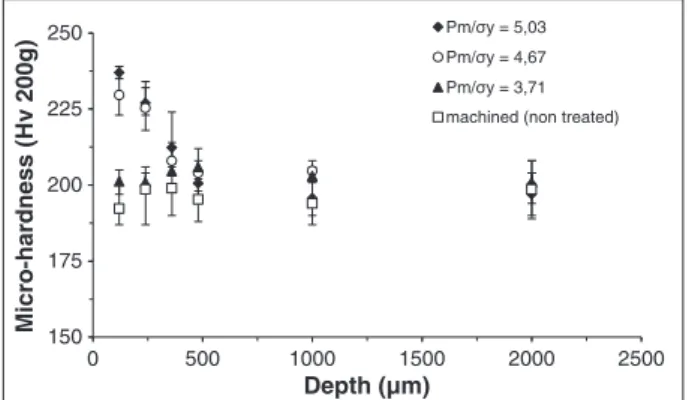
In order to measure the change in the mechanical properties after the combined turned and burnished process, microhardness measurements below the surfaces were conducted. Figure 13 shows the evolu-tion of the microhardness versus the depth for turned and combined turned and burnished surfaces. Microhardness measurements in the subsurface cross section proved that the work-hardened layer obtained after the combined process is about 350μm thick. These results confirm the tribologically transformed structure formation already mentioned in other situations.25–27
Analysing the microhardness and the residual stress evolution versus depth isfirst noted that the ma-chining has no significant effect on microhardness. However, the combined process affects the under layer microhardness, and a subsurface work hardening phenomena are observed. Second, residual stresses are affected by the combined process. In fact, residual stresses on the subsurface transit from residual tensile associated with machining to residual compressive stresses relative to combined ma-chining/burnishing process.
In this work, the combined machining/burnishing tool is used considering the same sketching con-ditions. However, these conditions can be varied in order to optimise their functioning concon-ditions.
150 175 200 225 250 0 500 1000 1500 2000 2500 Micro-hardness (Hv 200g) Depth (µm) Pm/ y = 5,03 Pm/ y = 4,67 Pm/ y = 3,71 machined (non treated)
Figure 13. Evolution of microhardness versus the depth below surface for non-treated and combined turned and burnished surfaces with different normalised mean contact pressure.
(a) (b) -700 -500 -300 -100 100 300 500 700 0 100 200 300
Tangential residual stress (MPa)
Depth (µm) machined (non treated)
combined machined/treated (Pm/ -700 -500 -300 -100 100 300 500 700 0 100 200 300
Axial residual stress (MPa)
Depth (µm) machined (non treated)
combined machined/treated (Pm/ y =5,03) y = 5,03)
Figure 12. Evolution of residual stress versus the depth below surface: (a) tangential residual stress and (b) axial residual stress.
CONCLUSION
A new combined machining/burnishing tool was designed and fabricated. This tool allows for simul-taneously machining (turning) and burnishing a cylindrical surface using a turning machine.
The C45 steel specimens have been turned under different conditions, sketches,finishing and half finishing using only the cutting tool. The evolutions of the surface roughness parameter Raand the technological time relative to every condition have been investigated. Using the combined machin-ing/burnishing tool at sketches conditions, the same parameters have been also investigated. A com-parison among the parameters obtained under different machining conditions and those obtained using the combined machining/burnishing tool shows that the combined tool allows, on one hand, for reducing the technological time from 9.6 using thefinishing condition to 5 s with coarse conditions, and on the other hand, for obtaining thefinishing roughness Rausing the combined tool at sketches conditions. The normalised mean contact pressure has been also varied, but its variation does not seem to have any significant effect.
The residual stress analyses show that using the combined machining/burnishing tool allows for in-ducing a compressive residual stress in the superficial layers. These analyses through cross sections for the machined and combined machined/burnished surfaces show that the stresses, initially positive near the surface, become compressive by using the combined machining/burnishing tool. These analyses also show that the combined tool induces a maximum residual stress at the surface. The microhardness measurements through a cross section show the subsurface work hardening phenomena. This under layer is harder than the bulk material.
Therefore, at sketched conditions, the combined machining/burnishing process decreases the surface roughness up to 0.46μm. This roughness is better than those obtained by machining at finishing, half finishing and sketching conditions. A surface roughness reduction of 77% compared with sketching and 58% compared withfinishing is reached. The combined machining/burnishing process improved the subsurface properties, particularly residual stress and microhardness. These properties enhance fa-tigue life and wear resistance of the parts.
REFERENCES 1. Weil R. Techniques d'usinage, Editions Dunod, Paris 1971.
2. Sharman ARC, Aspinwall DK, Dewew RC, Bowen P. Workpiece surface integrity considerations when finish
turninggammatitanium almunide. Wear 2000;294:473–481.
3. Pastor H. The evolution of cutting tool materials. Bulletin du Cercle d'Etudes des Métaux, Tome XVI 1996;13:7.1–7.11.
4. Baillon J. Des Matériaux (3ème édn). Presses Internationales Polytechniques: Montréal 2000.
5. Braham S. Modélisation du galetage des vilebrequins. Evolution des contraintes résiduelles sous chargement cyclique. Thèse de doctorat, Palaiseau, October 1991.
6. Hassan AM. The effect of ball and roller burnishing on the surface roughness of some non-ferrous metals. Journal of
Materials Processing Technology 1997;72:385–391.
7. Thamizhmanii S, Saparudin B, Hasan S. A study of multi-roller burnishing on non-ferrous metals. Journal of Achievements
in Materials and Manufacturing Engineering 2007;22(2):95–98.
8. Hassan AM, Al-Jalil HF, Ebied AA. Burnishing force and number of ball passes for the optimum surfacefinish of brass
components. Journal of Materials Processing Technology 1998;83: 176–179.
9. Hamadache H, Chaoui K. Aspect of superficial layer of Rb40 steel under ball and roller burnishing effect, in Second
Sym-posium on Heat Treatment of Metals and Alloys, Cairo 2004.
10. Némat M, Lyons AC. An investigation of the surface topography of ball burnished mild steel and aluminium. International
11. Fattouh M, Khabeery MMEL. Residual stress distribution in burnishing solution treated and aged 7075 Al alloy.
Interna-tional Journal of Machine Tools and Manufacture 1989;29(1):153–160.
12. Braslavski VM, Baraz AA. Deformation strengthening of machinery parts. Vestnik Machinostroeniya 1983;63(7):61–65.
13. El-Axir MH. An investigation into roller burnishing. International Journal of Machine Tools and Manufacture 2003; 40:1603–1617.
14. Luca L, Neagu-Ventzel S, Marinescu I. Effects of working parameters on surfacefinish in ball-burnishing of hardened
steels. Precision Engineering 2005;29:253–256.
15. El-Tayeb NSM, Low KO, Brevern PV. On the surface and tribological characteristics of burnished cylindrical Al-6061.
Tribology International 2009;42:320–326.
16. Rodríguez A, López de Lacalle LN, Celaya A, Lamikiz A, Albizuri J. Surface improvement of shafts by the deep
ball-burnishing technique. Surface and Coatings Technology 2012;206:2817–2824.
17. Laouar L, Hamadache H, Saad S, Bouchelaghem A, Mekhilef S. Mechanical surface treatment of steel-optimization
param-eters of regime. Physics Procedia 2009;2:1213–1221.
18. El-Axir MH, El-Khabeery MM. Influence of orthogonal burnishing parameters on surface characteristics for various
mate-rials. Journal of Materials Processing Technology 2003;132:82–89.
19. El-Taweel TA, El-Axir MH. Analysis and optimization of the ball burnishing process through the Taguchi technique.
Inter-national Journal of Advanced ManufacturingTechnology 2009;41:301–310.
20. Hamadache H, Laouar L, Zeghib NE, Chaoui K. Characteristics of Rb40 steel superficial layer under ball and roller
burnish-ing. Journal of Materials Processing Technology 2006;180:130–136.
21. Hokkirigawa K, Kato K. An experimental and theoretical investigation of ploughing, cutting and wedge formation during
abrasive wear. Tribology International 1988;21(1):51–57.
22. Hokkirigawa K, Kato K. The effect of hardness on the transition of the abrasive wear mechanism of steels. Wear 1988; 123:241–251.
23. Navas VG, Gonzalo O, Bengoetxea I. Effect of cutting parameters in the surface residual stresses generated by turning in
AISI 4340 steel. International Journal of Machine Tools and Manufacture 2012;61:48–57.
24. Fattough M, El-Khabeery MM. Residual stress distriburion in burnishing solution treated and aged 7075 aluminium alloy.
International Journal of Machine Tools and Manufacture 1989;29:153–160.
25. Mezlini S, Kapsa Ph, Henon C, Guillemenet J. Abrasion of aluminium alloy: effect of subsurface hardness and scratch
interaction simulation. Wear 2004;257:892–900.
26. Mezlini S, Ben Tkaya M, El Mansori M, Zahouani H, Kapsa Ph. Correlation between tribological parameters and wear
mechanisms of homogeneous and heterogeneous material. Tribology Letters 2009;33:153–159.
27. Elleuch K, Mezlini S, Fouvry S, Kapsa Ph. Friction damage of aluminium alloys. Industrial Lubrication and Tribology