STRAYLIGHT TESTS FOR THE HELIOSPHERIC IMAGERS OF STEREO
J.-M. Defise, J.-P. Halain, E. Mazy, P. Rochus
Centre Spatial de Liège - CSL Avenue du Pré-Aily, 4031 Angleur (Belgium)
Tel/Fax: 32-43-67.6668/.5613 [email protected]
ABSTRACT
The design of the Heliospheric Imager (HI) of the NASA Solar TErrestrial Relations Observatory (STEREO) is based on an optical baffle system. It will reject the solar disk light with attenuation of the order of 10-13 and 10-15, and let two separate camera systems (HI-1 and HI-2) measure the extremely faint solar coronal mass ejections. A multi-vane diffractive system has been optimized to achieve the lower requirement (10-13 for HI-1) and is combined with a secondary baffling system to reach the 10-15 rejection performance in the second camera system (HI-2).
The theoretical performances of the baffling systems will be experimentally verified during the instrument development phase. A specific straylight test facility is being studied at CSL and preliminary tests have been conducted to prepare the HI instrument testing. The test set-up requirements and design considerations are discussed in this paper. The very high rejection performance requires to perform those tests under vacuum to avoid ambient air perturbations. Several light trapping systems have been developed for this application. A first breadboard has been built and is currently under testing. Preliminary results of those tests are presented.
1. INTRODUCTION
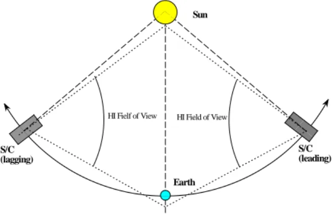
The STEREO program is a NASA mission dedicated to solar observations. Two spacecrafts will orbit around the sun with sufficient separation to provide remote sensing instruments with a stereoscopic view. Each spacecraft will include a Heliospheric Imager (HI) to view the heliosphere in the interval from 12 to 215 solar radii, which includes the Earth, as shown on Fig. 1
The HI experiment will obtain the first stereographic images of coronal mass ejections (CME) in interplanetary space. The key element of this instrument is the baffling system facing the sun, protecting the telescopes from solar disk, whose light is much brighter than the CME.
Earth HI Fielf of View Sun S/C (lagging) S/C (leading) HI Field of View
Fig. 1 STEREO mission orbit geometry
2. INSTRUMENT CONCEPT
Due to its very large field of view (more than 90 arcdeg), the HI field of view is shared into two camera systems (HI-1 and HI-2), with overlapping field of view. Both cameras will be active at very low light level.
Consequently, the key point in the HI instrument design is the optical baffle that reduces straylight to a very low level, in particular for the solar disk brightness ([2], [3], and [4]). The HI design is shown on Fig. 2. It consists on two optical systems. Two sets of baffle system allow the instrument to reach its baffling requirement: the forward baffle to keep the optical systems in the shadow of the solar brightness and the internal baffle to reject Earth and galactic straylight from HI 2.
Solar light
Forward Baffle Internal Baffle
HI 1 HI 2
Fig. 2 HI Design
The function of the forward baffle is to reject the solar disk light and, to a lower extent, the inner corona light from both the open interior.
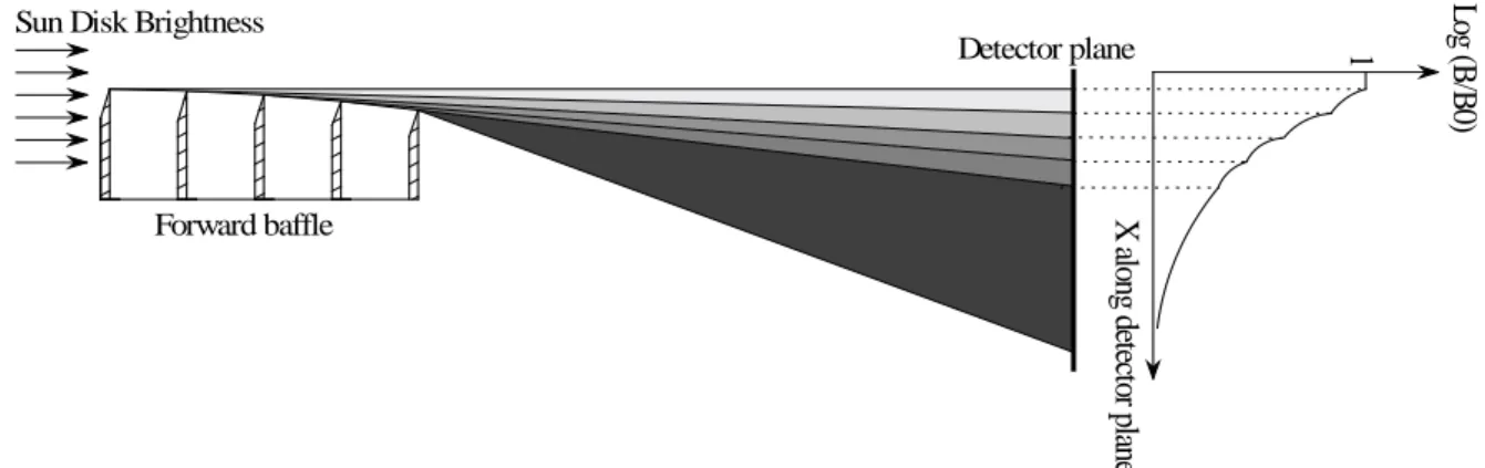
Forward baffle
Detector plane
Sun Disk Brightness Log
(B/ B0 ) X al ong det ect or pl ane 1
Fig. 3 Diffractive multi-vanes systems
To reach the required rejection level, a diffractive multi-vane baffle system was proposed. The vane edges are arranged in an arc such that the nth intermediate vane blocks the bright linear diffracting edge of the n-1th vane from the view of the n+1th vane edge, as shown on Fig. 3.
This multi-vane design is based on both laboratories tested baffle system for a similar heliospheric imaging experiment [5] and theoretical computation. The degree of solar disk rejection afforded by the forward baffle was computed using Fresnel’s second order approximation to the Fresnel-Kirchhoff diffraction integral for a semi-infinite half-screen [6].
Fig.4 Forward baffle rejection curve
The resulting cascading rejection curve for the optimised forward baffle is shown on Fig. 4. The rejection level (i.e. B/B0, where B0 is the sun flux and
B the measured flux) is 10-9 at the top entrance of the telescope. As the last vane edge of the forward baffle is out of the HI 1 field of view, a supplementary 10-4 rejection factor from entrance aperture allows the global rejection level lower than the required 3.10-13.
An internal baffle is used to provide higher level of rejection. Its main function is to reject residual Sun light, Earthshine and galactic straylight from HI-2.
3. STRAYLIGHT FACILITY
Straylight rejection is the key element to achieve good science with the instrument. Light from the solar disk must absolutely be suppressed. Therefore, it is of crucial importance to evaluate as much as possible the performance of straylight rejection.
The diffraction performance of multi-vane systems has not been tested before below ~ 10-8 mainly because of air particle diffusion [5]. In the case of the HI, the 5-vane system should produce rejection of 10-10. Consequently, a vacuum straylight facility is studied and prepared at the Centre Spatial de Liège (CSL) to measure the HI vane rejection level and validate the cascading application of Fresnel theory.
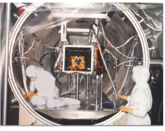
The major requirements for the vacuum facility are high cleanliness level and good mechanical stability. In order to fulfil the straylight requirement, the diffusion by particles onto the instrument environment has to be as small as possible: a class 100 clean room is required. In order to fulfil the alignment constrains during vacuum tests, the optical bench has to be vibration isolated during the test. The FOCAL 2 facility (2 m diameter, 1.35 m x 5 m optical bench) at CSL, shown on Fig.5, fulfils all these requirements.
The straylight test will be composed of two conceptual configurations. In the first case, a small optical system with a highly sensitive detector (i.e. a photomultiplier) will point toward the last vane edge and measure the
rejection level at various angles in order to verify the theoretical analysis. In the second case, the optical system will be adapted to match with HI-1 field of view and then simulate incoming straylight in HI-1.
Fig. 5 FOCAL 2 facility at CSL
The vacuum test set-up of the optical bench is composed of six components as shown in Fig. 6: the light source and collimator, the mock-up, the detector, the light traps and the black box.
To achieve an efficient straylight detection (10-10 level), the vanes are illuminated with an intense collimated pencil beam produced by a 20 W continuous laser diode. For that purpose, a collimator is used to send the beam onto the mock-up constituted by the vanes of the forward baffle system. One fraction of this beam is diffracted by the vanes towards the detector area while the remaining part is transmitted above the vanes or reflected by the first vane. These parts are absorbed by two specific light traps.
All these equipments in FOCAL 2 facility are surrounded by a black box in order to trap unwanted light and ensure a perfect black environment around the detector.
4. COMPONENTS OF THE TEST SET-UP
4.1 Light source and collimator
The Sun brightness is simulated by a 100-mm focal length collimator located in front of the five vanes mock-up.
The source of the collimator is a powerful 20 CW laser diode at λ = 808 nm with a 600 µm core optic fiber. To simplify the laser diode manipulation and cooling, the source is external to the vacuum chamber. An optic fiber feedthrough with an internal fiber transmit the light to the collimator focal plane.
The collimator design is mainly driven by two straylight requirements:
- First, the light flux out of the useful collimated beam, should be limited to avoid unwanted light flux into the vacuum chamber.
- Second, the aperture stop should not be seen directly by the detector and should not introduce diffracted straylight (by the forwards baffle) higher than the diffracted light to measure. A trade-off has been performed between the size and location of the output pupil and the ratio useful beam flux / injected flux in the focal plane.
Detector
Mock-up
Collimator
Black box
FOCAL 2
vacuum chamber
Optical FiberLight trap
Optical bench
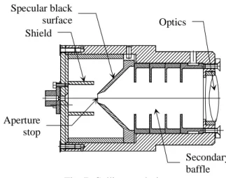
Diode laser Vacuum feedthroughThe collimator design is presented in Fig. 7. It is based on a 100-mm focal length commercially available achromat doublet and a 2-stage baffle system. The 5.7 x 2.4 mm² aperture stop is located before the optics in order to reject the output pupil far away from the mock-up.
The first stage of the baffle consists into a pyramidal “black” mirror, which reflects all useless light (outside the aperture stop) towards the collimator sides where it is diffuse. The shield prevents from a direct view between the collimator side and the focal plane area in front of the aperture stop. In all cases, the straylight need 5 specular or diffuse reflections before going through the aperture stop. The secondary baffle limits the useless beam that goes through the aperture stop.
Optics Shield Specular black surface Secondary baffle Aperture stop
Fig. 7: Collimator design
The ratio of useful beam flux / injected flux is not more than 11 % but the straylight induced by the collimator out of the collimated beam is mainly diffuse and lower than 5 10-6 times the useful beam flux.
4.2 Light trap
In order to reach the required signal to noise ratio, straylight has to be absorbed in the facility with dedicated light traps. Three types of light trap are necessary: one to cover the detector field of view, one to absorb the collimated beam reflected onto the first vane of the forward baffle and the last one to absorb the collimated beam transmitted above the forward baffle.
The two first light traps are manufactured by simple panels covered with ultra-black velvet applique [7]. A specific light trap is designed to absorb the part of the collimated useful beam that goes through above the forward baffle system. This high power collimated beam has not to induced straylight onto the detector, which can limit drastically the test performances.
The light trap design, shown on Fig. 8, is optimized for a nearly collimated beam coming from a particular orientation. Its rejection is defined by the ratio:
) ( entrance trap light the from coming flux light Total flux light incident Total ) ( direction all in direction along Rθ = θ
The light trap rejection for an input collimated beam in the normal incidence shall be better than 109 or
9 10 ) 0
(θ = >
R . The light trap rejection for light flux coming from any other direction (θ ≠0) shall be better
than 105 or 5 10 ) ( : 0 > ≠ ∀θ Rθ .
The light trap is designed in order to keep as much as possible the characteristic of the input beam: to avoid diffuse light. The optical design is based on a 800-mm length tube with vanes at the end from which are located successively a set of 2 density filters and a classical conical light trap. The input collimated beam interacts sequentially with a first density filter, which absorbs a part of the light and reflects the residual towards the second filter. At the end, the collimated beam is absorbed by a conical light trap coated with a glossy black paint. The back-scattered light, coming from the conical light trap and from the filters (mainly due to the micro-roughness scattering) is still limited by the entrance tube and its vanes, all coated with quasi-lambertian black paint.
The major contribution to the total rejection comes from the back-scattered light due to the first filter micro-roughness. As the surface micro-roughness is limited to 0.3 nm RMS for manufacturing limitations, the useful micro-roughness is still decreased by shadowing effect due to the high incidence angle (> 60 arcdeg). In such case, the rejection for input collimated beam in the normal incidence is better than 0.5 109 mainly due to the micro-roughness scattering of filters.
Conical light trqp Filter Assembly
Filter 1 Filter 2 Light trap entrance
Tube
Fig. 8: Light trap design
4.3 Black box
For limiting the environmental straylight onto the vacuum chamber bright wall, all OGSE’s are surrounded by copper panels with quasi-lambertian black paint. The black box consist in a 1.1x1.7x0.8 m³
rectangular base box. All corners and apertures are closed with black kapton.
4.4 Detector
The detector consists on a Hamamatsu photomultiplier tube with a GaAs(Cu) photocathode having 12 % quantum efficiency at 808 nm. The photomultiplier is used in photon counting mode in order to detect very faint signal. To decrease the internal dark signal lower than 20 counts/s, the photomultiplier is cooled down to -20°C.
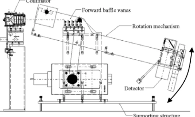
To limit the detected signal to useful light only, a simple optical system reduces the field of view as shown in Fig. 9. The size of the detector is the driven parameter for its design: in order to measure small diffraction angle without inducing large straylight in the vacuum chamber, the top edge of the detector has not to be directly illuminated by the collimated beam from the source. The design of the optics and mechanics takes into account this requirement: the entrance pupil is close of the top edge of mechanics.
The detector is supported by a rotating frame around the last vane edge of the forward baffle in order to scan the various diffraction angles. All parts of the frame and the detector are either black anodized or black painted or covered with black kapton.
Optics Folding mirror Photocathode Photomultiplier electronics Cooling system
Fig. 9: Detector design
4.5 The mock-up
Fig. 10: Mock-up design
The structure is mounted on a 3-points screwing table to ensure horizontal positioning. A 100-mm stepping motor is used to reach a 15° rotation of the detector structure via 200 steps. The top of mock-up supports the five aluminium vanes whose separations and heights may be changed. The front face of the first vane is polished to ensure perfect reflection of non-diffracted and non-transmitted flux into light trap in front of it.
5. PRELIMINARY RESULTS
5.1 Non-vacuum test
At first, the optical fibers components of the set-up were tested, and their attenuation (in dB) were measured. Table 1 shows examples of measured characteristics.
Optical component Attenuation (dB/km)
5m external optical fiber 4.3
1m internal optical fiber 0.843
Optical fiber feedthrough 2.4
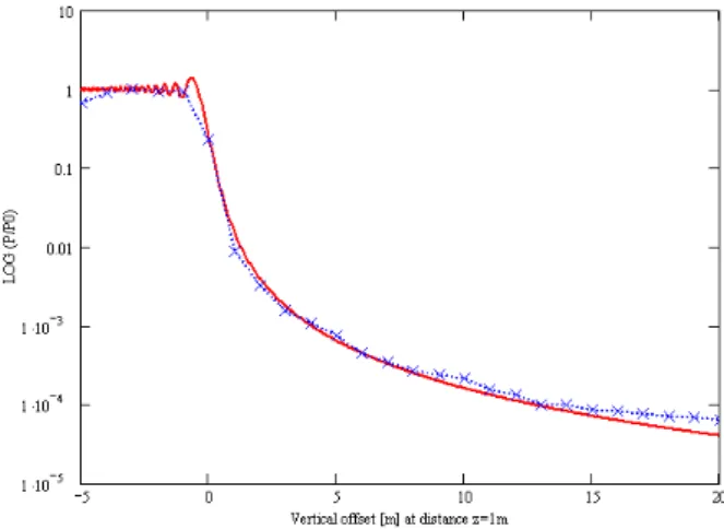
Table 1 Optical fiber components characteristics Next, the single vane rejection was measured to get a preliminary comparison with Fresnel theoretical curve. These measurements were realized in a black room with a 633-nm HeNe laser in a simple vane set-up, as shown on Fig.11.
HeNe Laser Collimating lens
The resulting single vane rejection level is shown on Fig.12 (y-axis in function of the detector vertical offset along x-axis, in mm). The dot line shows the measurements, and the solid line the Fresnel curve.
Fig. 12 Rejection of one vane in black room
We can list the conclusions of these preliminary tests: - The beam coming onto the vane edge must be as
large as possible to be representative of a plane wave hitting the edge.
- The black conditions of the room and the set-up must be very strict to avoid straylight coming into the detector.
- The pinhole in front of the detector must be sufficiently small to avoid de-convolution post processing.
5.2 Test plan
In the black room, the one vane rejection will be measured for the four tips of vane shown on Fig. 13 to determine the most efficient one [8], [9]. These measurements will be realized using the 808-nm laser diode to have more powerful beam. The A and B types are sharp edges with a 45° angle, while C and D tips are composed of a circular part of radius 1.41 and a straight part.
45°
2
45°
2
2
R 1,41
2
R 1,41
A
B
C
D
Fig. 13 Vane tips
In the vacuum chamber, a first set of measurements will be realised to compare single vane rejection level with theoretical Fresnel calculations. A second set of measurement will then be realised to measure rejection level of five vanes, inter-vane distance and vane heights being adaptable.
The complete set-up will later be re-used for the qualification model of HI to characterise the rejection level of the instrument forward baffle.
ACKNOWLEDGEMENTS
The Belgian contribution to the STEREO program is funded by the OSTC.
REFERENCES
1. D.G. Socker, R.A. Howard, C.M. Korendyke, G.M. Simnett, D.F. Webb, “The NASA Solar Terrestrial Relations Observatory (STEREO) Mission Heliospheric Imager,” SPIE 4139 (2), p. 284-293, 2000.
2. C. Leinert and D. Kluppelberg, “Stray Light Suppression in Optical Space Experiments,”
Applied Optics, 13, pp. 556-564, 1974.
3. R.P. Breault, “Problems and techniques in stray radiation suppression”, in Stray Light
Problems in Optical Systems, J.D. Lytle and
H.E. Morrow, eds., Proc. SPIE 107, 2-23, 1977.
4. A. Buffington, P. Hick, B.V. Jackson and C.M. Korendyke, “Corrals, hubcaps and
crystal balls: some new designs for very-wide-angle visible-light heliospheric imagers”, SPIE 3442, p. 77-83, 1998.
5. A. Buffington, B.V. Jackson, and C.M. Korendyke, “Wide-angle stray-light reduction for a spaceborne optical hemispherical imager, ” Applied Optics, 35, No. 34, pp. 6669-6673, 1996.
6. M. Born and E. Wolf, Principle of Optics, 6th edition, Pergamon Press, New York, 1980. 7. K. Snail et al., “Optical Characterization of
Black Appliques,” SPIE 2864, p. 465-474, 1996.
8. R.P. Breault, “Vane structure design trade-off
and performance analysis”, SPIE 967, p.
90-116, 1988.
9. R.D. Seals and M.B. McIntosh, “Advanced
Baffles: knife-edged diffuse-absorptive and dual reflective baffles”, SPIE 1753,