an author's https://oatao.univ-toulouse.fr/22837
http://doi.org/10.1109/TNS.2018.2885820
Melin, Gilles and Guitton, P. and Montron, R. and Gotter, T. and Robin, Thierry and Overton, B. and Morana, Adriana and Rizzolo, Serena and Girard, Sylvain Radiation resistant single-mode fiber with different coatings for sensing in high dose environments. (2018) IEEE Transactions on Nuclear Science. 1-7. ISSN 0018-9499
2 applications. In the case of single layered hard coatings,
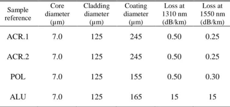
external stress applied perpendicular to the fiber direction acts as the repetition of very small radius bends to the fiber core along its length, leading to power dissipation through cladding higher-order modes. In order to mitigate this phenomenon that increases with wavelength, we increase the core/cladding refractive index difference (7.0×10⁻³) as compared to standard telecom fibers (∼5.5×10⁻³). Fiber core is made of pure silica, whereas cladding is made of fluorine-doped silica (∼2.0 wt% of fluorine). Core diameter is finally fixed to 7.0 µm in order to reach a LP11 cut-off wavelength close to 1250 nm, which allows fiber operation at both the second and third windows: 1310 nm and 1550 nm, respectively. At the same time, lowering micro-bending sensitivity also enhances resistance to macro-bending. We have indeed verified that the different fibers described in table I comply with ITU G657.A2 standard requirements related to bending loss, which is highly beneficial for future cabling prospects. As indicated in table II, we have selected two dual acrylate coatings, “ACR.1” (standard dual acrylate for telecom applications) and “ACR.2” (high temperature dual acrylate), both cured in line with UV lamps, one polyimide, “POL” cured in line with thermal furnaces, and the last one is an aluminum coating, “ALU” deposited in line from a melted bath. A typical fiber section after coating removal is presented in Figure 1.
TABLE I
CHARACTERISTICS OF DIFFERENT TESTED OPTICAL FIBERS Sample reference Core diameter (µm) Cladding diameter (µm) Coating diameter (µm) Loss at 1310 nm (dB/km) Loss at 1550 nm (dB/km) ACR.1 7.0 125 245 0.50 0.25 ACR.2 7.0 125 245 0.50 0.25 POL 7.0 125 155 0.50 0.30 ALU 7.0 125 165 15 15 TABLE II
CHARACTERISTICS OF DIFFERENT TESTED COATINGS Sample reference Coating type Maximum long term
operating temperature
ACR.1 Standard acrylate 85°C
ACR.2 High temperature
acrylate 150°C
POL Polyimide 300°C
ALU Aluminum 400°C
Fig. 1. Typical fiber cross-section
III. IRRADIATION CONDITIONS AND RIAMEASUREMENTS 100 m of each fiber sample listed in table I have been loosely coiled at a diameter of 80 mm. The coils were passively irradiated (without any injected optical power) under 60Co γ -rays at the IRSN IRMA facility, Saclay (France), up to a cumulated dose of 750 kGy(SiO2) at a dose rate of 0.37 Gy
(SiO2)/s and at room temperature (between 25-30°C). Spectral
attenuation measurements have been performed one month after irradiation in the wavelength range between 1450 nm and 1650 nm using the well-known cut-back technique. RIA is obtained by the difference of spectral attenuation after/before irradiation. Figure 2 compares RIA spectral dependence of the four different samples. ACR.1, ACR.2 and ALU samples, which have been drawn in similar conditions, exhibit a comparable RIA of ∼25 dB/km at 1550 nm. POL sample, drawn at a ∼5× lower draw speed in order to ensure complete coating crosslinking, also exhibits a slightly reduced RIA,
∼18 dB/km at 1550 nm. A lower drawing speed also reduces the glass cooling rate. Therefore, strained bonds, which are known to act as precursor sites for point defects causing the RIA in such fibers, may be less favored in the case of POL samples.
Fig. 2. Spectral RIA of the different samples after passive irradiation up to 750 kGy(SiO2) at room temperature
ACR.2 sample was selected to undergo a 60Co γ-rays irradiation with online RIA monitoring at SCK-CEN, Mol (Belgium), up to a cumulative dose of 3.0 MGy(SiO2) at dose
rate of 5.2 Gy(SiO2)/s. Optical signals at both wavelengths
were provided by two broadband super luminescent diodes providing each a total output power of 1.2 mW. Temperature remained stable all along the irradiation at roughly 42°C. Figure 3 presents RIA evolutions at 1310 nm and 1550 nm. Raw data are represented with open circles and their best fit curves with bold lines.
Fig. 3. Online RIA at 1310 nm and 1550 nm for ACR.2 coated fiber under irradiation up to 3.0 MGy(SiO2)
The obtained online RIA at 3.0 MGy(SiO2), 20 dB/km at 1310
nm and 27 dB/km at 1550 nm, are higher than the reported ones in [1], 11 dB/km at 1310 nm and 20 dB/km at 1550 nm (with ∼30× less injected optical power), for a radiation hardened fiber with both fluorine-doped core and cladding. Our tested sample exhibits a similar RIA at 1550 nm in both irradiation scenarios (online and offline), whereas cumulated dose is ∼4× higher in the case of online measurement. This is most likely due to the strong impact of photo-bleaching on the RIA of the investigated optical fibers. Is it worth noticing that light power was not found to have a significant impact in the case of fluorine-doped core single-mode fibers up to a maximal dose of 10 kGy(SiO2) when injected optical power
rises from 40 µW to 0.35 mW [1]. Photo-bleaching was found to be efficient in such fibers by injecting 40 mW of light at 980nm during irradiation up to 110 kGy(SiO2) [10]. For
distributed sensing applications up to the ∼MGy range, we believe that it is really important to take into account the real optical power which is used by the various possible architectures of commercially available interrogators. This is particularly relevant for safety systems which shall operate 24 hours a day in an “ON” state. Therefore accessible sensing length for a given radiation hardened fiber depends not only on the fiber characteristics but also on the selected sensing technology and its operation characteristics. As an example, typical double-ended BOTDA (Brillouin Optical Time Domain Analysis) will operate at a few mW, whereas typical single-ended BOTDR (Brillouin Optical Time Domain Reflectometer) will operate at about 500 mW.
IV. FIBER MECHANICAL STRENGTH EVALUATION Optical fiber reliability under harsh radiation environment is also a crucial issue. No degradation of fiber mechanical strength was observed when various acrylate coated fibers underwent 500 kGy(SiO2) of 60Co γ-rays [11]. Improvement
was even measured after 2.35 MGy(SiO2) of 60Co γ-rays due
to enhanced coating crosslinking [12]. Our fiber samples were subjected twice to 750 kGy(SiO2) IRMA runs, ending up a
cumulated dose of 1.5 MGy(SiO2). Fiber tensile strength was
measured according to IEC 60793-1-31 using an uniaxial table top tensile tester from FIBER SIGMA with a fiber gauge of 0.5 m. Figures 4 and 5 present respectively results obtained for acrylate coated samples and for polyimide/aluminum coated ones for a strain rate of 30 mm/min which corresponds to an elongation of 6 %/min.
Fig. 4. Tensile strength measurement before/after irradiation for both sets of acrylate coated fibers
(red and orange labelled points are almost fully superposed)
Fig. 5. Tensile strength measurement before/after irradiation for polyimide and aluminum coated fibers
4 Unlike ACR.2, ACR.1 sample exhibits a strongly degraded
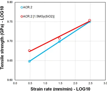
mechanical behavior after irradiation, with breaks that occur even at low applied stress. We clearly observed that the primary ACR.1 coating lost most of its adhesion to the glass part, therefore stress corrosion through moisture ingression is strongly favored. For ACR.2 samples, we did not observe any variation of tensile strength nor stripping force required to remove the coating. POL samples do not suffer from any mechanical degradation after irradiation neither. ALU samples exhibit a quite broad failure strength repartition, their median value drops about 20% after irradiation. In order to estimate dynamic fatigue corrosion factor, we extend tensile strength measurements to strain rates ranging from 3 mm/min to 300 mm/min of fiber elongation. Obtained mean values over 15 samples for each fiber type are summarized in table III. Standard deviation of those measurements is of 0.05 GPa.
TABLE III
MEASURED MEAN TENSILE STRENGTH Sample reference Strain rate 3mm/min Strain rate 30mm/min Strain rate 300mm/min ACR.2 4.45 GPa 5.00 GPa 5.62 GPa ACR.2
[1.5MGy(SiO2)]
4.74 GPa 5.10 GPa 5.67 GPa POL 4.85 GPa 5.39 GPa 5.81 GPa POL
[1.5MGy(SiO2)]
4.86 GPa 5.47 GPa 5.89 GPa
We estimate the dynamic fatigue corrosion factor, nd as
defined in IEC 60793-1-3 standard by fitting mean tensile strength versus strain rate in logarithmic scale. nd equal to
1/p - 1 (where p is the obtained slope), is a standardized indicator of fiber mechanical behavior. It shall reach at least 18.0 in order to comply with IEC 60793-2-50. Figures 6 & 7 present the obtained results, respectively for ACR.2 and POL coated fibers before/after irradiation. Table IV summarizes calculated values of dynamic fatigue corrosion factor, nd and
respective uncertainties for 95% of confidence as calculated in IEC 60793-1-3 standard.
Fig. 6. Tensile strength measurement versus strain rate before/after irradiation for ACR.2 samples
Fig. 7. Tensile strength measurement versus strain rate before/after irradiation for POL samples
TABLE IV
MEASURED DYNAMIC FATIGUE CORROSION FACTOR Sample
Reference nd mean nd maxi (95%) nd mini (95%)
ACR.2 18.8 19.3 18.2 ACR.2 [1.5MGy(SiO2)] 24.6 26.3 23.0 POL 24.6 25.8 23.6 POL [1.5MGy(SiO2)] 22.8 24.2 21.5
High temperature acrylate coated fibers exhibit a significant increase of nd, from ∼19 before irradiation to ∼25 after
irradiation at the MGy dose level, as already pointed out in [12]. For polyimide coated fibers, we notice a limited drop of nd, which is hardly significant and remains much higher than
the safe value of 18.0 defined by the standard. To summarize our results, all tested samples comply with standardized mechanical strength requirements after irradiation in the MGy dose range, apart from the ones coated with ACR.1 coating. It is worth noticing that we only test one specimen for each coating type, so this result shall not be generalized to the variety of coatings available on the market. Aluminum coated fibers were not included in this study as such a metallic coating is hermitic towards moisture and therefore prevents tensile strength dependence to strain rate.
V. THERMAL COATING DEGRADATION
We use thermal gravimetric analysis in order to investigate thermal degradation of polyimide coated fiber samples. This coating type offers the best compromise between extended operating temperature, low fiber attenuation and industrial availability. A small amount of coated fiber (∼10 mg) is placed into the platinum crucible of a thermo-balance [13] and is subjected to a temperature ramp of 2°C/min under air. Relative mass loss curve of the coating part versus temperature is given in figure 8.
Fig. 8. TGA curves of polyimide coated fiber before/after irradiation
Polyimide coating exhibits an accelerated thermal degradation after being irradiated. As the chosen temperature ramp is quite high, accelerated mass loss occurs above 350°C. At high temperature in an air environment, oxygen diffuses into the surface of the polymer, attacking directly the polymer with the release of carbon dioxide, carbon monoxide, and water. The rate of degradation is controlled by the rate of the oxygen diffusion which is accelerated due to polymer network
weakening after such a high dose of γ-rays. Life-time prediction is extracted from TGA curves based on Arrhenius formalism [14] in order to get a quantitative comparison of coating thermal degradation kinetic before/after irradiation. The instantaneous rate of weight change, dW/dt, is a function of temperature. It is approximated by the running average of weight change over small intervals of temperature. By applying the Arrhenius relation, dW⁄dt=A.exp(-Ea⁄RT), the
familiar plot ln(dW/dt) versus 1/T is generated from high temperature data (420°C to 485°C), as shown in figure 9 for POL samples before/after irradiation. Table V gives the values of pre-exponential factor A, Ea/R and determination
coefficient R² for both sample types.
Fig. 9. Arrhenius plots of weight change rate versus inverse temperature for polyimide coated fiber before/after irradiation
TABLE V
ARRHENIUS PLOT FIT COEFFICIENTS FOR BOTH SAMPLES Sample
Reference A Ea/R R² from fit
POL 18.854 16664 0.9824
POL [1.5MGy(SiO2)] 14.576 12996 0.9914
From those data, time to reach a given coating mass loss under isothermal condition in air can be evaluated over a broad operating temperature range. Obtained life-time prediction is given in figure 10, using a quite stringent failure criterion of 20 wt% mass loss [14].
Fig. 10. Life-time prediction of polyimide coated fiber before/after irradiation for a 20 wt% mass loss criteria
6 As already shown in figure 5, we did not observe any
significant degradation of irradiated polyimide coated fibers, when their tensile strength is measured at room temperature. However, TGA analysis reveals that irradiation has a detrimental impact on polyimide coating ability to withstand high temperature, leading to reduce its operating lifetime after an exposure to a γ-rays cumulated dose of 1.5 MGy(SiO2). As
an example, at 300°C, their long term recommended temperature of operation, the thermal stability of polyimide coating fibers decreases from more than 300 days down to about 45 days after this huge radiation dose of γ-rays.
VI. CONCLUSION
A specific single-mode radiation hardened fiber has been developed based on requirements of distributed sensing applications under high cumulated dose, typically up to the MGy dose level. Four different coatings were tested in order to allow possibly operation at elevated temperature: a dual acrylate combination for telecom applications, a dual high temperature acrylate combination, polyimide and aluminum. The fiber index profile has been optimized in order to reduce micro-bending contribution to total attenuation, in particular for the case of hard coatings. RIA measured offline exhibits a slight dependence on draw speed, which results from technical constraints, such as available UV or thermal power to complete the coating cure. Comparison between online and offline RIA measurements indicate that the tested fibers are strongly sensitive to photo-beaching, in particular under high cumulated dose. This dependence towards injected optical power will influence the optical power budget calculation in a real sensing configuration. Therefore, the maximum sensing length for a given total cumulated dose will also depend on the interrogator parameters such as injected optical power and dynamic range. Mechanical strength measurements after irradiation indicate that the use of some standard dual acrylate for telecom applications may be detrimental towards fiber reliability. Specialty coatings such as high temperature acrylate, polyimide or aluminum allow safe operation under irradiation up to the MGy dose level at (or close to) room temperature. Finally, thermo-gravimetric analysis has been performed on irradiated polyimide coated fiber samples. It is clear that irradiation degrades the coating ability to withstand elevated temperatures for long periods of time. But, we consider that polyimide remains a good candidate for distributed sensing applications [15] as it exhibits an interesting trade-off between extended operating temperature, low fiber attenuation and industrial availability. Aluminum coating remains also of interest for applications at higher temperatures (above 300°C) such as those encountered in the nuclear industry although its use is much less common with potential end-users. To conclude, it will be worth evaluating how these coatings behave in the case of combined high temperature/high cumulated dose constraints, not merely from a mechanical point of view, but also because it has been shown that increasing the temperature of irradiation does not necessarily lead to reduced RIA levels [16]. For that purpose, the effect of combined temperature and irradiation (X-rays or
γ-rays) is currently under investigation using a specific set-up that better simulates real operating conditions.
REFERENCES
[1] T. Wijnands, K. Aikawa, J. Kuhnhenn, D. Ricci, and U. Weinand , “Radiation Tolerant Optical Fibers: From Sample Testing to Large Series Production”, Journal of Lightwave
Technology, vol. 29, no. 22, pp 3393-3400 Nov. 2011,
10.1109/JLT.2011.2168512.
[2] X. Bao and L. Chen, “Recent Progress in Distributed Fiber Optic Sensors”, Sensors, vol. 12, pp 8601-8639, June 2012, 10.3390/s120708601.
[3] A.F. Fernandez, P. Rodeghiero, B. Brichard, F. Berghmans, A.H. Hartog, P. Hughes, K. Williams, and A.P. Leach, “Radiation-tolerant Raman distributed temperature monitoring system for large nuclear infrastructures”, IEEE Transactions on
Nuclear Science, vol. 52, no. 6, pp 2689-2694, Dec. 2005,
10.1109/TNS.2005.860736.
[4] S. Delepine-Lesoille, S. Girard, M. Landolt, J. Bertrand, I. Planes, A. Boukenter, E. Marin, G. Humbert, S. Leparmentier, J.L. Auguste, and Y. Ouerdane, “France’s state of the art distributed optical fiber sensors qualified for the monitoring of the French underground repository for high level and intermediate level long lived radioactive wastes”, Sensors, vol. 17, no. 6, P1377, June 2017, 10.3390/s17061377.
[5] I. Toccafondo, Y.E. Marin, E. Guillermain, J. Kuhnhenn, J. Mekki, M. Brugger, and F. Di Pasquale, “Distributed Optical Fiber Radiation Sensing in a Mixed-Field Radiation Environment at CERN”, Journal of Lightwave Technology, vol.
35, no. 16, pp 3303-3311, Aug. 2017,
10.1109/JLT.2016.2608849.
[6] S. Girard, A. Morana, A. Ladaci, T. Robin, L. Mescia, J.J. Bonnefois, M. Boutillier, J. Mekki, A. Paveau, B. Cadier, E. Marin, Y. Ouerdane, and A. Boukenter, “Recent advances in
radiation-hardened fiber-based technologies for space
applications”, Journal of Optics, vol 20, no. 9, Aug. 2018, Art. no. 093001.
[7] S. Girard, J. Kuhnhenn, A. Gusarov, B. Brichard,
M. Van Uffelen, Y. Ouerdane, A. Boukenter, and C. Marcandella, “Radiation Effects on Silica-based Optical Fibers: Recent Advances and Future Challenges”, IEEE Trans. Nucl.
Sci., vol. 60, no. 3, pp 2015-2036, Feb. 2013, 10.1109/TNS.2012.2235464.
[8] B. Brichard, M. Van Uffelen, A.F. Fernandez, F. Berghmans,
M. Decréton, E. Hodgson, T. Shikama, T. Kakuta,
A. Tomashuk, K. Golant, and A. Krasilnikov, “Round robin evaluation of optical fibres for plasma diagnostics”, Fusion
Engineering and Design, vol. 56–57, pp 917–921, Oct. 2001.
[9] A.L. Tomashuk, E.M. Dianov, K.M. Golant, R.R. Khrapko, and D.E. Spinov, “Performance of special radiation-hardened optical fibers intended for use in the telecom spectral windows at a mega-gray level”, IEEE Trans. Nucl. Sci., vol. 45, no. 3, pp 1566–1569, June 1998.
[10] Y. Kim, S. Ju, S. Jeong, S. Ho Lee, and W.T. Han, “Gamma-ray radiation response at 1550nm of fluorine-doped radiation hard single-mode optical fiber”, Optics Express, vol. 24, no. 4, pp. 3910-3920, Feb. 2016, 10.1364/OE.24.003910.
[11] B.T. Huffman, P.K. Teng, and A.R. Weidberg, “Further studies of the effect of radiation on the mechanical strength of optical fibers”, Journal of Instrumentation, no. 8, P12002, Dec. 2013. [12] B. Risch, B. Overton, J. Rosko, A. Bergonzo, G. Kuyt, and
G. Mélin, “Optical Fiber and Cable Reliability for Radiation
Environments”, presented at 61st IWCS Conference, Charlotte,
USA, Nov. 11-14, 2012.
[13] http://www.tainstruments.com/products/thermal-analysis/thermogravimetric-analysis/.
[14] A. Stolov, D. Simoff, and J. Li, “Thermal stability of specialty optical fibers”, Journal of Lightwave Technology, vol. 26, no. 20, pp 3443-3451, Oct. 2008, 10.1109/JLT.2008.925698.
[15] C. Sabatier, V. Lecoeuche, S. Girard, G. Mélin, T. Robin, B. Cadier, L. Mescia, A. Morana, Y. Ouerdane, A. Boukenter, A. Champavère, and E. Marin, “Distributed optical fiber sensor for temperature/strain discrimination in radiation environments”, presented at RADECS 2018, Paper E-6, Gothenburg, Sweden, Sept.16-21, 2018, submitted to IEEE Trans. Nucl. Sci., 2018. [16] S. Girard, C. Marcandella, A. Morana, J. Perisse, D. Di
Francesca, P. Paillet, J.R. Macé, A. Boukenter, M. Léon-Pichel, M. Gaillardin, N. Richard, M. Raine, S. Agnello, M. Cannas, and Y. Ouerdane, “Combined High Dose and Temperature Radiation Effects on Multimode Silica-based Optical Fibers”,
IEEE Trans. Nucl. Sci., vol. 60, no. 6, pp 4305-4313, Dec.