OATAO is an open access repository that collects the work of Toulouse
researchers and makes it freely available over the web where possible
Any correspondence concerning this service should be sent
to the repository administrator:
tech-oatao@listes-diff.inp-toulouse.fr
This is an author’s version published in:
http://oatao.univ-toulouse.fr/21275
To cite this version:
Turpin, Christophe and Morin, Benoit and Bru, Eric and
Rallières, Olivier and Roboam, Xavier and Sareni, Bruno and
Garcia Arregui, Marcos and Roux, Nicolas Power for Aircraft
Emergencies: A Hybrid Proton-Exchange Membrane H2\/O2
Fuel Cell and Ultracapacitor System. (2017) IEEE
Electrification Magazine, 5 (4). 72-85. ISSN 2325-5897
Official URL:
https://doi.org/10.1109/MELE.2017.2758879
n the context of aviation, this article looks at replacing a ram air turbine (Rat) with a hybrid proton-exchange membrane (PeM) hydrogen/oxygen (h2/o2)
fuel cell and ultracapacitor system, start-ing from a theoretical perspective. the structure we propose
has two static power converters: one associated with fuel cells and the other with ultracapacitors. the energy management principle presented (frequency sharing) enables two types of control. first, the converter associ-ated with the fuel cell manages the voltage of the dc bus, and then the converter associated with the ultraca-pacitors controls the high-frequency currents. second, the voltage of the dc bus is oppositely controlled by the ultracapacitor converter.
II
Digital Object Identifier 10.1109/MELE.2017.2758879
Power for Aircraft
Emergencies
A hybrid proton-exchange membrane
H
2
/O
2
fuel cell and ultracapacitor system.
By Christophe Turpin, Benoît Morin, Eric Bru,
Olivier Rallières, Xavier Roboam, Bruno Sareni,
Marcos Garcia Arregui, and Nicolas Roux
an experimental validation (at a reduced ratio scale of 1:10) allows for an analysis of the proposed principles. the experiment is conducted in two stages. in the initial vali-dation, a fuel cell physical emulator is used as the main source, before introducing an actual fuel cell.
Fuel Cells and Aircraft
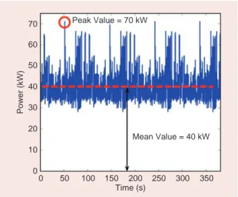
in the context of the More electric aircraft (Weimer 1993), one of the concepts supported by the european More open electrical technologies project, the electrical power requirements of an aircraft are set to increase (Roboam et al. 2012) thanks to recent advances in power electronics (Rosero et al. 2007). an aircraft may be sub-ject to various failures, in particular to the total loss of the engines or electrical power. these failures must remain acceptable (Mehdi and Woods 1989). for most large aircraft, a backup system composed of a Rat is used to generate emergency power (Bolognesi 2009). as new and future flight control actuators are electrical (van Den Bossche 2003), the load profile supplied by this backup system is very intermittent (figure 1). as the increase in electrical power demand is becoming very restrictive for the aircraft structure, which must include an increasingly large Rat, researchers have been look-ing at replaclook-ing this turbine with a fuel cell (Garcia-arregui 2007). in addition, a fuel cell system has other advantages compared to the current Rat system’s prop-erties (Wörner 2009): it operates independently of the aircraft’s speed and altitude; it can be stopped at any time if the main engines are recovered, while the Rat cannot be retracted once it has been extended; and it may reduce maintenance. Motapon et al. have also recently conducted and presented research in canada with experimental tests on replacing the Rat with a hybrid fuel cell.
the fuel cell indirectly [via reduction–oxidation reac-tion (redox)] makes h2 react with o2 ( Pera et al. 2013).
there are several possible strategies for supplying the gases (Garcia-arregui 2007). h2 may be produced on
board by reforming kerosene (Lenz and aicher 2005, ibarreta and sung 2006), or embedded in a compressed form. o2 may be taken from the ambient air using a
compressor or carried in a compressed form. all scenari-os were examined and assessed by Garcia-arregui, and the most relevant solution for the emergency power application would be carrying both gases in a com-pressed form, which would eliminate the complex stage of reforming the kerosene and ensuring the quantity and/or quality of the air in the event of an emergency. this h2/o2 solution is studied and experimentally
vali-dated in this article.
Research on fuel cell applications in aviation goes beyond the mere use in emergency power units (curtin 2010). a fuel cell could replace the gas turbine that cur-rently performs the auxiliary power unit (aPU) function, which essentially supplies the aircraft with power when
it is on the ground. this would reduce aircraft noise and gas emissions on the ground. a hybrid fuel cell/battery system has been proposed to perform this function (eid et al. 2010). Looking even further into the future, the hybridization of a high-temperature fuel cell and a tur-bine for this aPU has been studied (Rajashekara et al. 2008). in the elektrische Basissysteme in einem cfK Rumpf: architektur und auslegung project (2007–2009, funded by the federal Ministry of economics and tech-nology/airbus, eYi-058/07) in Germany, researchers are studying various applications based on fuel cells (Wörner 2009): the emergency power unit, multifunctional fuel cell system (power, water, and inerting), and green taxiing on the ground. incorporating fuel cells in aviation would seem to require multifunctional technology to compete with the other current highly integrated technologies.
Given the intermittent character of the emergency profile to be achieved as displayed in figure 1, it is useful to associate a source with high specific power with the main power source to avoid oversizing (turpin et al. 2012). therefore, the current Rat has already been the subject of optimization studies (to reduce its size and weight) by associating it with ultracapacitors (Roboam et al. 2011, Rafal et al. 2010) based on the duration of the intermittent loads to be satisfied (high power peaks but with relatively low energy). for a fuel cell emergency power unit, there is also the issue of not oversizing the fuel cell ( Jiang and Dougal 2006). however, there are other reasons to justify this hybridization, such as in Martínez et al., or Bizon et al. for vehicles, e.g., for h2/air
operation, it can also be used to compensate for the dynam-ics of the air compression (Zhan et al. 2008).
the work in this article is in line with previous theo-retical work conducted in the context of the european ceLina—fuel cell application in a new configured air-craft—project. several electrical architectures have been
70 60 50 40 30 20 10 0 0 50 100 150 200 250 300 350 Time (s) Mean Value = 40 kW Power (kW) Peak Value = 70 kW
Figure 1. A typical load profile for the sizing of an emergency power system (approach phase).
studied (Garcia-arregui 2007, Morin et al. 2014) for associ-ating fuel cells with ultracapacitors. here, the focus is on the architecture that uses two dc–dc converters: one for the fuel cell and the other for the ultracapacitor.
Description of the Hybrid System
various loads used in an emergency may be considered constant. this is because the electronic equipment (computers) and anti-icing items absorb power that is constant over time for the duration of the emergency mission. other equipment, such as fuel pumps, radio equipment, and lights, absorb constant power when used. however, some loads are very variable, in particu-lar the flight control actuators, which require power that fluctuates substantially depending on the flight condi-tions and practically throughout the whole mission.
During the ground approach phase, the aircraft’s speed is reduced, which means that a significant deflection of the flight control surfaces is required to direct the aircraft. this results in considerable power consumption. in addition, prior to landing, several maneuvers are performed by the pilot to adjust the position of the aircraft with respect to the target. the flight mission we selected (see figure 1) is the low-speed ground approach phase of an aircraft flying in a turbulent environment with maneuvers controlled by the pilot. We defined this as the main mission for siz-ing our study (Garcia-arregui 2007), i.e., highly variable power consumption that reaches the highest con-sumption peaks.
this mission profile has a mean power of 40 kW and consumption peaks reaching 70 kW, i.e., a 30-kW differ-ence between the mean power to be supplied and the maximum sizing power for the system. an oversizing rate (ovsR) can be defined as follows:
(Power) (Power) mean(Power)
. . OVSR max max
70 3 70 3 40 3 0 42 e e e = -= - = (1)
an ovsR close to zero means that power consump-tion does not vary, while an ovsR close to one means that the sizing power is used only occasionally. in addi-tion, generally speaking, a fuel cell requires fluidic auxil-iaries with a slow dynamic response, whereas in an emergency mission, the required power must be avail-able instantly. as a result, hybridization appears to be necessary in this case.
the new avionics standard that seems to be appear-ing in terms of the voltage level is a dc bus voltage of +270 vdc/0 vdc/−270 vdc (eid et al. 2010, Ravel 2009). the ultracapacitor is a good candidate for hybridization due to its qualities: high specific power, easy management of the state of charge, long lifetime and life cycles, and enough storable/returnable energy for our mission pro-file (Roboam et al. 2011, Langlois 2006, Maxwell technol-ogies inc.).
several solutions are possible for associating a fuel cell with ultracapacitors, as proposed by Garcia-arregui. We take various criteria into account to classify the solutions: weight, gas consumption, stability of the dc bus, ease of use, fuel cell load current, filtering capacity of the ultracapaci-tors, and system reliability. according to Garcia-arregui, the solution that offers the best compromise for our specifica-tions is the one that uses two static converters: one for the fuel cell and the other for the ultracapacitors (figure 2). this solution has the best bus stability and filtering capacity as well as middling weight and gas consump-tion, but its use and reliability are yet to be proven as the architecture puts a lot of strain on the power electronics.
We used several criteria to ini-tially size the solution. the issue was to determine the optimal num-ber of cells to be connected in series to create the fuel cell and their sur-face area. for example, it is possible to oversize the cell surface to re -duce gas consumption. Weight is therefore saved for storing gas, but the fuel cell is made heavier so a compromise must be reached. an important criterion in sizing the power electronics is the minimum voltage of the fuel cell. at equivalent power, the lower the cell voltage, the higher the current flowing through the semiconductors.
as for the stored energy, it is important to ascertain its capacity and its minimum reference voltage, allowing for a discharge of less than
Auxiliaries Fuel Cell Storage dc Bus dc/dc Auxiliary Converter dc–dc Fuel Cell Converter dc–dc Storage Converter +270 V –270 V
Figure 2. A solution using two dc–dc converters for the hybridization of a fuel cell and ultracapacitors.
50% of its voltage (i.e., 75% of its state of charge). the max-imum voltage of the stored energy is used to determine the number of elements to be connected in series. its capacity indicates how many branches of these elements are to be connected in parallel, with the elements being selected from ultracapacitor manufacturers’ catalogues.
table 1 contains an example of sizing, with an arbi-trary choice of criteria to set some general figures. sub-sequently, the following criteria remain variable to optimize the weight of the overall system and its gas consumption:
x
xfuel cell minimal voltage (v) = 100
x
xultracapacitor maximal voltage (v) = 80
x
xultracapacitor maximal discharge (%) = 50
x
xcutoff frequency (hz) = 0.05
x
xfuel cell maximal current density (a/cm2) = 0.5
x
xswitching frequency (hz) = 20,000
x
xnumber of parallel converter branches = four.
Theoretical Energy Management
for the Studied Hybrid System
Frequency Sharing Principle
hybridization in terms of power is defined as the associa-tion of various complementary sources. in our case, this association is achieved with a source of high specific energy (the fuel cell), which poorly withstands rapid vari-ations in power (schindele et al. 2005, thounthong and sethakul 2007), and a source of high specific power (ultra-capacitors), which can only supply or absorb the mean power of zero (excluding losses). the idea of this power hybridization is to assign low variations in power to the fuel cell and zero mean power to the ultracapacitors. sev-eral methods are available for this, including the distribu-tion of frequency powers band and slope limitadistribu-tion. the method chosen for this study is power frequency sharing (chapoulie and astier 1998, Garcia-arregui 2007) and is shown in figure 3.
the desired filtering frequency will play a significant role in sizing the solution because, for a specific stored energy capacity, a lower frequency will cause the energy level of the ultracapacitors to fluctuate more. in other words, given the ultracapacitors’ limitations (the maxi-mum voltage level not to be exceeded and the minimaxi-mum power reserve to be retained), at a given filtering frequen-cy, a minimum stored energy capacity must be used for the system to be able to operate. in our case, this filtering frequency enabled us to size the stored energy capacity and its reference voltage. this frequency was recom-mended by a fuel cell manufacturer as the fastest fre-quency enabling the auxiliaries to correctly control the gas supply (the pressure and flow rate), despite the varia-tions in fuel cell consumption.
an example of power frequency sharing is simulated in figure 4. the presented case is an ideal scenario, taking into account neither the losses in the components nor the
auxiliary consumption used to demonstrate frequency sharing. the mission profile is given in figure 1, and the filtering frequency is 50 mhz.
figure 5 shows the changes in voltage for stored energy and fuel cells throughout the mission for the sizing pro-posed in table 1. Using an ideal model, the state of charge of the stored energy and the limitation voltage of the fuel cell are within their limitations.
P
f Power-Sharing
Frequency
Power to Be Supplied by the Main
Energy Source
Power to Be Provided by the Storage
Figure 3. The principle of hybridization by frequency filtering, illustrat-ed in a power–frequency drawing.
TABLE 1.
An example of ideal hybrid system
sizing (with no losses).
Fuel CellSurface (cm2) Fuel Cell Number C (F) V 0 (V)
627.2 154 9.83 61.16
C: equivalent capacitance of ultracapacitors; V0: Initial ultracapacitor voltage.
70 80 60 50 40 30 20 10 0 –10 –20 0 50 100 150 200 250 300 350 400 Time (s) Power (kW) Load
Storage Device Power Fuel Cell Power
Impact of System Losses
now, let us consider some losses in the system, in particu-lar in the stored energy elements (the internal resistance of the ultracapacitors), as shown in figure 6. an observation
can be made that the state of charge of the stored energy is no longer within its limitations and that it moves toward a total discharge. in this case, the application quickly becomes no longer able to operate because all of the ener-gy lost in stored enerener-gy losses is never compensated.
the solution put forward to maintain the state of charge of the stored energy is to add a proportional control loop coupled with a low-pass filter on the ultracapacitor voltage, as shown in figure 7. the difficulty in choosing this correc-tor lies in choosing the proportional gain value K. With a gain K that is too low, the corrector will not be able to main-tain the stored energy at a state of charge stable enough to be within its limitations. With a gain K that is too high, the stored energy voltage undulates at the frequency of the low-pass filter placed at the ultracapacitor voltage mea-surement point. Without this low-pass filter, high-frequen-cy variations in the ultracapacitor voltage are carried onto the current provided by the fuel cell, which we aim to avoid. in addition, complying with the voltage limitations chosen for the stored energy is strongly linked to its reference volt-age. additionally, this loop must be included in the control of the system converter that is current controlled (with ultracapacitors first and fuel cells second) is because the converter that controls the bus voltage no longer has any degrees of freedom (Dof) to perform an additional function, in which case the bus voltage would be degraded.
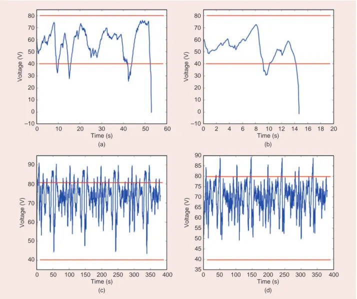
figure 8 shows various choices for the Vref and K
parameters of the control loop for the state of charge of the stored energy and the importance of the choice of these values for system stability. With a stored energy reference voltage that is too low, its mean state of charge cannot ful-fill the entire mission. With a reference voltage for the stored energy that is too high, there is a risk of exceeding the maximum ultracapacitor voltage values. the choice of these values can help reduce (or increase, if poorly chosen) 70 80 90 60 50 40 30 20 10 0 –10 0 10 20 30 40 50 60 70 80 90 100 Time (s) Voltage (V) RUC = 0.02 Ω RUC = 0.01 Ω RUC = 0 Ω
Figure 6. The ultracapacitor (UC) voltage evolution, taking into account losses due to internal resistances.
Vmes V Storage Storage Vref – + K Iref
Figure 7. A control loop for the state of charge of the stored energy. 85 80 75 70 60 65 55 50 45 40 35 0 50 100 150 200 250 300 350 400 Time (s) 0 50 100 150 200 250 300 350Time (s) 400 (a) (b) Voltage (V) 112 110 108 106 104 102 100 98 Voltage (V)
the size of the stored energy system. subsequently, the system sizing algorithm chooses these values.
in the prior discussed example (see table 1), resizing the stored energy and its control loop using an iterative process from the optimization algorithm gives rise to the results in table 2. taking into account the stored energy losses and adding a loop to maintain the state of charge leads to a stored energy resizing that is around 23% high-er than for the system when considhigh-ered with no losses. it is also used to determine the criteria (reference voltage, proportional gain, and initial minimum voltage of the stored energy) enabling the mission to be performed, complying with the limitations set for the state of charge of the stored energy and ensuring its optimal operation (see in figure 9).
Final Simulation Results
two versions of the PeM fuel cell were studied by Garcia-arregui: an h2/o2 stack and an h2/air stack. the weight
savings that can be achieved with an h2/o2 stack (higher
specific power and no compressor) is consequently can-celed out due to the weight of the o2 to be carried (mainly
the weight of the tanks). for the weight minimization cri-teria, the solution from the theoretical studies is therefore the h2/air solution. During the simulations, we considered
a rather pessimistic scenario in which we took into account auxiliary consumption (mainly compressor con-sumption) equal to 20% of the fuel cell production as well as the losses in the converters (losses in switches, induc-tors, and capacitors). the simulation result for this system sizing is given in figure 10.
80 70 60 40 30 20 50 10 0 –10 0 10 20 30 40 50 60 Time (s) (a) (b) Voltage (V) 80 70 60 40 30 20 50 10 0 –10 0 2 4 6 8 10 12 14 16 18 20 Time (s) Voltage (V) 90 80 60 70 50 40 0 50 100 150 200 250 300 350 400 Time (s) 0 50 100 150 200 250 300 350Time (s) 400 (c) (d) Voltage (V) 90 85 75 80 70 65 60 55 50 45 35 40 Voltage (V)
Figure 8. Some choices of parameters for the state-of-charge control loop: (a) gain = 5, Vref = 60; (b) gain = 1.5, Vref = 60; (c) gain = 5, Vref = 72; (d) gain = 1.5, Vref = 72.
TABLE 2.
The results of iterative resizing with
compensation for losses.
Vref (V) Gain C (F) V0 (V)
fuel cell production was noted to be higher than the mean load power. this would have also been valid in nonhybrid cases, taking into account the converter losses and the auxiliary consumption. however, the fuel cell supplies few high-frequency compo-nents, which should enable its com-pressor to correctly control the air supply flow rate and not speed up its aging. compared to the ideal case presented in figure 4, apart from the mean value for the power produced by the fuel cell, which differs for the reasons given above, slightly larger fluctuations can be seen for the sup-plied power. these fluctuations are
due to the stored energy charging loop, which itself is dependent on its capacitance.
Implementation of the Selected
Energy Management
DC Bus Voltage Control Strategy
as the architecture has two static converters, there is a Dof for controlling the bus voltage because there are three components connected to the dc bus: the loads, the stored energy and its converter, and the fuel cell and its convert-er. only one of these elements can manage the bus volt-age. clearly, the loads cannot do this. it is therefore possible to control the bus voltage via the fuel cell con-verter or the stored energy concon-verter.
Both of these solutions are shown in figure 11. in some cases, it is of particular interest to assign the bus voltage management to the stored energy. this is true, e.g., when the fuel cell is replaced by a Rat, as maximum power
point tracking can be associated with it (Rafal 2010, Langlois 2006). however, there currently seems to be mini-mal industry interest in a fuel-cell-based solution.
Regardless of the choice of dc bus control, frequency sharing must be performed as shown in figure 3, i.e., the high-frequency power compo-nents required by the application must be supplied by the ultraca-pacitors and the low-frequency components by the fuel cell. this is achieved by a filter applied to the measured load current (figure 11). the difference between both possible bus control strategies is that, when it is the fuel cell that commands the dc bus voltage [i.e., strategy one, figure 11(a)], the converter associated with the stored energy must be more dynamically effective than the converter associated with the fuel cell. if it is less effective, the fuel cell will also inevitably supply the high-frequency components to control the bus. for strategy two [figure 11(b)], the fuel cell will supply the low-fre-quency components only in the event its converter direct-ly receives this instruction.
Dynamic Compensation of Losses
as explained in the “impact of system Losses” section, losses in the converters and stored energy have a slow effect (low frequencies) on the state of charge of the stored energy and, therefore, on the system sizing. Ultimately, the fuel cell will have to supply power for these losses to main-tain the state of charge for the stored energy.
however, for the strategy shown in figure 11(a), these losses by the stored energy will consequently have only a
7 8 6 5 4 3 2 1 0 –1 –2 0 50 100 150 200 250 300 350 400 Time (s) Power (W) ×104 Load Power Ultracapacitor Power Fuel Cell Power
Figure 10. The power sharing obtained via simulation for the weight- and consumption-optimized system.
85 80 75 70 60 65 55 50 45 40 35 0 50 100 150 200 250 300 350 400 Time (s) Voltage (V)
Figure 9. The change in stored energy voltage in resizing for the case in question (Table 1).
The high-frequency
power components
required by the
application must
be supplied by the
ultracapacitors and
the low-frequency
components by the
fuel cell.
partial supply of the high-frequency part of the load cur-rent, and this noncompensated part will therefore be found in the fuel cell current. Given the nature of the stored energy converter [dc–dc, bidirectional in current, working as a booster in the stored energy to bus direction (Rafal 2010)], it enables the current in the stored energy or the bus voltage to be controlled. in this case, we would like to control the converter output current, i.e., on the bus side, as the converter’s instruction is to supply the high frequen-cies of the load current so that the fuel cell does not have to supply this part. as this current management method is not permitted because of the nature of the converter and we were not able to control this in our experimental sys-tem, a way of managing the current on the bus side would be to apply the voltage ratio to the reference current of the stored energy. this transposition requires a yield per unit from the converter. in practice, with no specific action, the final current at the bus will be lower than the current required. to be able to control the bus current via this con-verter, the chosen method is to add a converter loss com-pensation loop. the current was therefore managed as
. ,
I I V VPL
Converter HVdc
HVdc stor stor Diodes IGBT
, + + + (2)
where IConverterHVdc is the output current of the converter and Istor is the input current to be managed. the equation
includes converter losses. however, it is difficult to ascertain them in real time. We chose to compensate for them via a theoretical estimation. this is because the converter losses are mainly composed of losses in the switches (3) and (4)—here, the insulated-gate bipo-lar transistor (iGBt) and diode—in addition to losses in the passive elements (5):
( , )
( ( ( , ) ( , )) )
P V I P P
VCE Ir R Ir 2 E V I E V I fdec IGBT cond comm
eff ON OFF o r IGBT IGBT $ $ $ = + = r+ + + (3) ( , ) ( ) ( ( , ) ) P V I P P V ID d R Id 2 E V I f Diode cond comm
eff REC dec
o d Diode Diode $ $ $ = + = r + + (4) ( ) . P IL =R IL$ L2 (5)
therefore, in requiring the stored energy to supply the high-frequency parts of the load power and the losses Fuel Cell Fuel Cell Storage Storage Vbus Vbus Iload Iload Vmes Vmes Imes Imes Imes Imes Vref Vref Iref Iref Iref Iref + + + + + + – – – – – – C (s) C (s) C (s) C (s) C (s) C (s) HP Filter LP Filter Load Load Current Piloted Current Piloted Voltage Piloted Voltage Piloted (a) (b)
Figure 11. The DoF offered by the chosen architecture: (a) the bus managed by the fuel cell (strategy one); (b) the bus managed by the stored energy (strategy two). HP: high pass; LP: low pass.
calculated for its converter, full compensation for the load power high frequencies is close to being achieved. the mean value for these losses does not affect the control loop for the state of charge of the stored energy, as the losses are considered to be an additional load and go through the high-pass filter for the frequency sharing in figure 11(a). the disadvan-tage of this method is that, if the esti-mation of these losses is incorrect or if they change over time (through component wear and tear),
compen-sation no longer functions. the ideal solution would be a bidirectional dc–dc current converter for which we man-age the current on the high-voltman-age side.
there is a similar situation for the strategy shown in [figure 11(b)] because the converter associated with the fuel cell is a dc–dc unidirectional current boost convert-er (in the fuel cell to bus direction). it enables the man-agement of the fuel cell current or the bus voltage. here, we want to manage the current sent to the bus. as for the previous case, the losses are compensated by a theoretical estimation and considered to be an addi-tional load. they therefore go through the low-pass fil-ter for frequency sharing and are compensated using a mean value. the compensation for these losses has less of an effect on the hybridization performance as they have a low-frequency effect, which would be com-pensated for by the control loop for the state of charge of the stored energy.
Problem Starting the Frequency Sharing
effective filtering for the fuel cell requires a low cutoff frequency for the frequency-sharing filter (here, 10 mhz). this means a long starting time for the filter. Used as is, the filter rise corresponds to the rise in the fuel cell cur-rent, i.e., during that whole time, the stored energy pro-vides the power required for the loads. as the stored
energy cannot fulfill this mission for long, it becomes fully discharged when the fuel cell reaches the mean current required by the frequency-sharing filter. Meanwhile, the bus voltage is no longer controlled as the stored energy is discharged and the mission is not fulfilled. at startup, there is an issue initializing this fil-ter. Let us suppose that we are not aware of the steady state; we, there-fore, cannot initialize the filter at its value in the steady state or at the value of the current at the startup time (in which case, we would risk starting on a peak). to compensate for these difficulties, we suggest successive-ly switching to slower and slower filters to arrive at the final desired filter. therefore, the chosen solution (shown in figure 12) proposes starting with a fast filter (for which the cutoff frequency depends on the dynamics accept-able by the fuel cell and its fluidic regulations), while other slower filters start at the same time. Given the order of two and the damping factor ( 2 2) of the filters, / they naturally have a slight exceedance, which means that their values will inevitably coincide for a limited profile. this will enable switching to the lower-frequency filter with no value jumping. to prevent a return from a low-frequency filter to a higher-frequency filter, switch-ing should be irreversible.
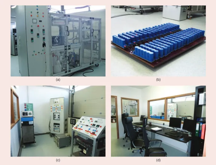
Small-Scale Experimental Validation
Description of the Experiment Performed
the experimental validation shown in figure 13 takes place in two stages. the first is an experiment with the fuel cell replaced by an emulator, and the second is with an actual fuel cell. these trials will be used, among other things, to assess the relevance of an experiment employ-ing an emulator and will guide the choice for full-scale validation. in addition, the use of the emulator is less restrictive than using a fuel cell in terms of the cost of gas and the risk of damage. it is used to adjust and vali-date all the control loops and push the strategies to their limits, with minimal risks for the equipment.
for the fuel cell, we have a stack of 50 cells measuring 130 cm2, with h
2/o2 operation, provided by aReva energy
storage inc. [figure 14(a)]. for the stored energy, we are equipped with 16-v, 58-f ultracapacitors (Maxwell tech-nologies’ BMoD0058 e016). they will be connected in series, in a sufficient number to adapt to the level of the reference voltage for the stored energy [figure 14(b)].
the load profile will be to scale based on the bench ele-ments, i.e., 4 kW mean power and 8 kW peak power. Given the unique elements of the bench, the experiment could not take place in the exact sizing conditions resulting from the optimization.
2 1.8 1.6 1.4 1.2 1 0.8 0.6 0.4 Amplitude (p.u.) 0.2 0 0 50 100 150 Time (s)
ILoad IFast Filter
ISlow Filter ISwitched Filter
IMed Filter
Figure 12. An example of filter switching. p.u.: per unit.
The use of the
emulator is less
restrictive than
using a fuel cell in
terms of the cost
of gas and the risk
of damage.
Emulation of a Fuel Cell
the fuel cell emulator consists of a programmable voltage source, with its output voltage adjusted to suit the current output so as to correspond to the almost static curve of a fuel cell. its transfer function (taken from fontes et al. 2007 and Rallieres 2011) is given by
. . .. ln . . .. .ln . V N E n FR T P P/ R Tn F j jj R j fc n eq 0 1 2 0 H2 O2 a = d + ^ h- d + n- n (6)
where N is the number of cells in the stack, E0 the standard
nominal voltage of the h2/o2 redox pair, R the perfect gas
constant, T the fuel cell temperature, n the number of elec-trons involved in the reaction, f faraday’s constant, and PH2
and PO2 the respective partial pressures of h2 and o2.
in addition, a (the transfer coefficient), jn (the
cross-over equivalent current density), j0 (the exchange
cur-rent density), and Req (the membrane and diffusion
equivalent surface resistance) are parameters taken per fitting on the actual almost static curve of an aReva energy storage elementary cell, where j = I/S is the cur-rent density going through our emulated fuel cell.
the experiment was conducted with a 1:10 ratio for the power with respect to the simulation results (Garcia-arregui 2007). in addition, it was performed on a high-voltage dc half bus (i.e., +270 vdc/0 vdc instead of +270 vdc/0 vdc/−270 vdc), which, in the end, is a 1:5 ratio for the power involved for this half bus.
figure 15 shows power sharing via frequency filtering operated with the fuel cell emulator described previously.
We can see actual filtering of the load power by the stored energy. for both of these cases, we can see a cer-tain thick area for the power supplied by the fuel cell. this thick area is due to our fuel cell emulator because the voltage source used for the emulator takes its power from the french network (230 vac/400 vac, 50 hz) to sup-ply its power. it is composed of a three-phase rectifier, then a dc–dc converter, which unfortunately allows some of the fundamental harmonic of the rectified network through (six times the network frequency, i.e., 300 hz). as acquisition is performed with a step of 1 ms, these undu-lations appear.
however, for strategy one [figure 15(a)], the high-fre-quency undulations are even more present. as expressed in the “dc Bus voltage control strategy” section, this is due to a fuel cell converter bandwidth that is higher than the bandwidth of the stored energy converter, as well as an estimation of the dynamic losses for this converter that is not accurate, as it is based on theoretical calcula-tions. the frequency band for these phenomena is found at the fuel cell current, as the frequencies are too high to be managed by the stored energy converter. this frequen-cy band is in addition to the 300-hz undulation supplied by the fuel cell emulator.
System Stability
Using the emulator tests the system to its limits and notably tests the stored energy stability. to test this power manage-ment stability, we considered two situations that are theoret-ically the worst cases that could cause the system difficulties:
Fuel Cell Supervision
Fuel Cell Emulator
Fuel Cell Stack 50 Cells–130 cm2 Electrical Supervision dc–dc Chopper dc–dc Chopper Storage
Electrical Power Center
Active and Resistive Loads Ultracapacitors Supplier: Saft Batteries Lithium-Ion Battery Supplier: Maxwell Technologies 0..150 Vdc 30..100 Vdc0..140 A ..610 Vdc0..16 A 0..900 A 45 kW
Low Voltage: High Voltage:
0..325 Vdc ..650 Vdc
(–90)..90 A (–45)..45 A Low Voltage: High Voltage:
HVdc Bus
+ –
(a) (b)
(c) (d)
Figure 14. Photos of the test bench elements: (a) the fuel cell test bench; (b) the ultracapacitors; (c) the electrical prototypes; (d) and the moni-toring room. 8 6 4 2 0 –2 Power (kW) 0 100 200 300 400 Time (s) (a) 8 6 4 2 0 –2 Power (kW) 0 100 200 300 400 Time (s) (b) Load Power Ultracapacitor Power Fuel Cell Power Load Power
Ultracapacitor Power Fuel Cell Power
Figure 15. Power sharing achieved via an experiment with a fuel cell emulator: (a) a bus managed by the fuel cell (strategy one); (b) a bus man-aged by the stored energy (strategy two).
x
xcase 1: the load disconnects (step of nominal one to zero); all of the current supplied by the fuel cell is therefore absorbed by the ultracapacitors; they charge but must above all not exceed their maxi-mum voltage.
x
xcase 2: the load reconnects (step of zero to nominal one); the ultracapacitors empty to supply the power required for the load, but they must not discharge too substantially so the system can continue to operate. this is shown in figure 16, where we guarantee that the state of charge for the stored energy does not endan-ger the system when faced with these two situations. the high and low limits for the stored energy are 150 v and 0 v.
figure 17 shows the purpose of the stored energy charging loop described in the “impact of system Losses” section. indeed, when this loop is not present, the stored energy starts to completely discharge, and the more its state of charge decreases, the higher the requested cur-rents, which makes the voltage decrease even further at its limitations.
the issue of starting for hybridization mentioned in the “Problem starting the frequency sharing” section must be experimentally validated to check the stability of the filter switching with the stored energy charging loop. this is because hybridization, when starting, is launched with all of the power consumed by the loads supplied by the stored energy; its state of charge decreases very quickly, and its control loop will tend to increase the power supplied by the fuel cell to recharge it. figure 18 shows this startup for a test with an emula-tor. the fuel cell quickly reaches its nominal power, and we can easily distinguish between the moments where the frequency-sharing filter switches thanks to the
harmonics present on the power supplied by the fuel cell. the experiment on the fuel cell power increase is in line with the theoretical switching of the filters shown in figure 12. Power (kW) Voltage (V) 0 20 40 60 80 100 120 140 Time (s) 130 –4 –2 0 2 4 6 120 110 100 90 80 70 60 50
Load Power Ultracapacitor Power Fuel Cell Power
Ultracapacitor Voltage
Figure 16. A stored energy charging loop enters into difficulty.
100 80 60 40 20 0 0 5 10 15 20 Time (min) Voltage (V) Storage Voltage
Removal of the Charging Loop
Figure 17. A stored energy charging loop suppression.
8 7 6 5 4 3 2 1 0 –1 –20 10 20 30 Time (s) 40 50 Load Power Ultracapacitor Power
Fuel Cell Power Switching Filter
Power (kW)
Tests with an Actual Fuel Cell
the tests in figure 15 were repeated with the real fuel cell stack, the characteristics of which are given in the “Description of the experiment Performed” section.
figure 19 shows the hybridization tests with the fuel cell stack for both strategies put forward in this article. the same phenomena as in figure 15 can be seen, with one less high-frequency undulation because a significant part of the high-frequency part present at the power supplied by the fuel cell emulator was due to the three-phase electrical network. as the fuel cell is a dc source, these undulations no longer appear. however, even more harmonics provided by the fuel cell are found in strategy one for the same rea-sons as in the “emulation of a fuel cell” section, i.e., a stored energy converter that is less dynamically effective than the fuel cell converter.
Conclusions
Going from simulation to experiment confirmed the theo-retical results but also revealed phenomena that were not apparent during the simulations (e.g., interference between the converters, voltage rise of the elements, connections between them, immunity to noise, resonance, and so forth). in addition, while figures 10 and 19 are relatively similar, we can see that the mean current provided by the fuel cell dur-ing the simulations (figure 5) is higher than that observed in the experiment. this is due to the ultracapacitor technology, which had developed in the meantime (the internal resis-tance is now lower than during the theoretical study), but is also due to the scale factor, which considered the losses to be greater in the more powerful converters. however, the emulation showed very satisfactory results with respect to the experiment with an actual fuel cell, confirming all of the
potential offered by fuel cell emulation (e.g., to go toward full scale in terms of power). this work was continued by replac-ing the ultracapacitors with a battery for different aviation specifications ( Jaafar et al. 2014).
Acknowledgments
the authors would like to thank france’s General Director-ate for civil aviation for funding this article as part of the iss Power and control project led by airbus. this study was conducted in partnership with airbus and the aKKa technologies Group.
For Further Reading
J. a. Weimer, “electrical power technology for the more elec-tric aircraft,” in Proc. 12th AIAA/IEEE Digital Avionics Syst. Conf., oct. 1993, pp. 445–450.
x. Roboam, B. sareni, and a. D. andrade, “More electricity in the air: toward optimized electrical networks embedded in more-electrical aircraft,” IEEE Ind. Electron. Mag., vol. 6, no. 4, pp. 6–17, 2012.
J. a. Rosero, J. a. ortega, e. aldabas, and L. Romeral, “Moving toward a more electric aircraft,” IEEE Aerosp. Electron. Syst.
Mag., vol. 22, no. 3, pp. 3–9, Mar. 2007.
i. s. Mehdi and e. J. Woods, “electrical power systems for high mach vehicles,” in Proc. IEEE Energy Conversion Engineering
Conf., Washington, Dc, 1989, pp. 625–630.
P. Bolognesi, f. Papini, and L. taponecco, “hybrid-excitation dc machines as highly reliable generators for ram air turbines,” in Proc. IEEE Industrial Electronics Society Conf., Porto, Portugal, 2009, pp. 2569–2574.
D. van Den Bossche, “More electric control surface actua-tion: a standard for the next generation of transport aircraft,” in Proc. 10th European Power Electron. and Applicat. Conf., tou-louse, france, 2003, pp. 1–6.
M. Garcia-arregui. (2007). theoretical study of a power generation unit based on the hybridization of a fuel cell stack and ultracapacitors. Ph.D. dissertation, institut. nat. Polytech., 8 6 4 2 0 –2 Power (kW) 0 100 200 300 400 Time (s) (a) 8 6 4 2 0 –2 Power (kW) 0 100 200 300 400 Time (s) (b) Load Power Ultracapacitor Power Fuel Cell Power Load Power
Ultracapacitor Power Fuel Cell Power
Figure 19. Power sharing achieved via an experiment with an actual fuel cell: (a) a bus managed by the fuel cell (strategy one); (b) a bus man-aged by the stored energy (strategy two).
toulouse, france. [online]. available: http://ethesis.inp-toulouse.fr/archive/00000521/
a. Wörner, “fuel cells and hydrogen for airborne applica-tions,” in Proc. NWV 7th Nat. Hydrogen and Fuel Cell Conf., arn-hem, Germany, Dec. 2009.
s. n. Motapon, L. Dessaint, and K. al-haddad, “a com-parative study of energy management schemes for a fuel-cell hybrid emergency power system of more-electric aircraft,” IEEE Trans. Ind. Electron., vol. 61, no. 3, pp. 1320– 1334, 2014.
s. n. Motapon, L. Dessaint, and K. al-haddad, “a robust-consumption-minimization-based energy management strategy for a fuel cell hybrid emergency power system of more electric aircraft,” IEEE Trans. Ind. Electron., vol. 61, no. 11, pp. 6148–6156, 2014.
M. c. Pera, D. hissel, h. Gualous, and c. turpin, eds.,
Electro-chemical Components. hoboken, nJ: Wiley, 2013.
B. Lenz and t. aicher, “catalytic autothermal reforming of jet fuel,” J. Power Sources, vol. 149, pp. 44–52, sept. 2005.
a. f. ibarreta and c.-J. sung, “optimization of Jet-a fuel reforming for aerospace applications,” Int. J. Hydrogen Energy, vol. 31, no. 8, pp. 1066–1078, 2006.
s. curtin, “fuel cells flying high,” Int. Airport Rev., no. 4, pp. 36–39, 2010.
a. eid, h. el-Kishky, M. abdel-salam, and t. el-Mohandes, “Modeling and characterization of an aircraft electric power system with a fuel cell-equipped aPU connected at hvDc bus,” in Proc. 2010 IEEE Power Modulator and High Voltage Conf.
(IPMHVC), atlanta, Ga, pp. 639–642.
K. Rajashekara, J. Grieve, and D. Daggett, “hybrid fuel cell power in aircraft,” IEEE Ind. Applicat. Mag., vol. 14, no. 4, pp. 54–60, 2008.
c. turpin, s. astier, x. Roboam, B. sareni, and h. Piquet,
Sys-temic Design Methodologies for Electrical Energy Systems. hobo-ken, nJ: Wiley, 2012.
x. Roboam, o. Langlois, h. Piquet, B. Morin, and c. turpin, “hybrid power generation system for aircraft electrical emer-gency network,” IEEE IET Trans. Elect. Syst. Transp., vol. 1, no. 4, pp. 148–155, 2011.
K. Rafal, B. Morin, x. Roboam, e. Bru, c. turpin, and h. Piquet, “hybridization of an aircraft emergency electrical network: experimentation and benefits validation,” in Proc.
IEEE Vehicle Power and Propulsion Conf. (VPPC), Lille, france, 2010, pp. 1–6.
Z. Jiang and R.a. Dougal, “a hybrid fuel cell power supply with rapid dynamic response and high peak-power capacity,” in Proc. 21st IEEE Applied Power Electronics Conf. and Exposition, Dallas, tx, 2006, pp. 1250–1255.
J. s. Martínez, D. hissel, M. c. Péra, and M. amiet, “Practical control structure and energy management of a testbed hybrid electric vehicle,” IEEE Trans. Veh. Technol., vol. 60, no. 9, 2011.
n. Bizon, M. stork, and M. oproescu, “fuel cell hybrid power source for pulsed current loads,” in Proc. IEEE 2012 Int.
Conf. Applied Electronics, 2012, pp. 25–28.
Y. Zhan, Y. Guo, J.-G. Zhu, and h. Wang, “Power converters and controllers for UPs applications with backup PeM fuel cell,” in Proc. IEEE Industry Applications Society Annu. Meeting, 2008, pp. 1–8.
B. Morin, D. van Laethem, c. turpin, o. Rallières, s. astier, a. Jaafar, o. verdu, M. Plantevin, and v. chaudron, “Direct hybridization fuel cell–ultracapacitors,” Fuel Cells, vol. 14, no. 3, pp. 500–507, 2014.
P. Ravel, “electrical distribution of high power: impacts, technologies,” in Proc. More Electric Aircraft Forum, Barcelona, spain, sept. 2009, pp. 8–11.
s. J. Moura, J. B. siegel, D. J. siegel, h. K. fathy, and a. G. stefanopoulou, “education on vehicle electrification: Battery systems, fuel cells, and hydrogen,” in Proc. IEEE Vehicle Power
and Propulsion (VPPC), Lille, france, 2010, pp. 1–6.
P. flynn, Meeting the Energy Needs of Future Warriors. Wash-ington, D.c.: national academies Press, 2004.
o. Langlois (2006). conception d’un réseau de secours électrique pour l’aéronautique. Ph.D. dissertation, institut. nat. Polytech., toulouse, france. [online]. available: http:// ethesis.inp-toulouse.fr/archive/00000243/
Maxwell technologies inc. (2017). Maxwell. [online]. available: www.max well.com
L. schindele, M. Braun, and h. spath, “the influence of power electronic dynamics on PeM fuel cell system,” in Proc.
IEEE EPE Conf. Power Electronics and Applications, Dresden,
Ger-many, 2005, pp. 1–9.
P. thounthong and P. sethakul, “analysis of a fuel starva-tion phenomenon of a PeM fuel cell,” in Proc. IEEE Power
Con-version Conf. (PCC), nagoya, Japan, 2007, pp. 731–738.
P. chapoulie and s. astier, “Modelling of an electric vehi-cle including ultracapacitors with saBeR,” in Proc. Int. Electric
Vehicle Symp. Exposition, Brussels, Belgium, sept. 1998, pp. 1–3. aReva energy storage inc. aReva. [online]. available: www .areva.com
G. fontes, c. turpin, s. astier, and t.a. Meynard, “interac-tions between fuel cells and power converters: influence of current harmonics on a fuel cell stack,” IEEE Trans. Power
Elec-tron., vol. 22, no. 2, pp. 670–678, 2007
o. Rallieres, “Modélisation et caractérisation de piles à combustible et électrolyseurs PeM,” Ph.D. dissertation, insti-tut. nat. Polytech., toulouse, france, 2011.
n. Lapena-Rey, J. Mosquera, e. Bataller, f. ortı, c. Dudfield, and a. orsillo, “environmentally friendly power sources for aerospace applications,” J. Power Sources, vol. 181, no. 2, pp. 353–362, 2008.
a. Jaafar, c. turpin, x. Roboam, e. Bru, and o. Rallières, “energy management of a hybrid system based on a fuel cell and a battery,” in IEEE Int. Conf. Modeling and Simulation of
Elec-tric Machines, Converters and Systems (ElectrIMACS), valencia, spain, 2014, pp. 1–6.
Biographies
Christophe Turpin (turpin@laplace.univ-tlse.fr) is with the Université de toulouse, france.
Benoît Morin (benoit.morin@cea.fr) is with the french atomic energy and alternative energy commission, the Research institute on new energy technologies and nano-materials, Grenoble, france.
Eric Bru (bru@laplace.univ-tlse.fr) is with the Université de toulouse, france.
Olivier Rallières (rallieres@laplace.univ-tlse.fr) is with the Université de toulouse, france.
Xavier Roboam (roboam@laplace.univ-tlse.fr) is with the Université de toulouse, france.
Bruno Sareni (sareni@laplace.univ-tlse.fr) is with the Université de toulouse, france.
Marcos Garcia Arregui (marcosgarcia.arregui@gmail .com) is with General electric, Belfort, france.
Nicolas Roux (roux@laplace.univ-tlse.fr) is with the Université de toulouse, france.