UNIVERSIT´E DU QU´EBEC
Institut National de la Recherche Scientifique ´
Energie, Mat´eriaux et T´el´ecommunications
ACCESS CONTROL IN FULL-DUPLEX
WIRELESS NETWORKS
Master of Science (M.Sc) Thesis in Telecommunication Engineering
By Elaheh Askari
Research Director Prof. Sonia A¨ıssa, INRS-´EMT
Internal Examiner Prof. Douglas O’Shaughnessy, INRS-´EMT External Examiner Dr. Roch Glitho, Concordia University
ABSTRACT
Access Control in Full-Duplex Wireless Networks
by Elaheh Askari
Single-channel full-duplexing is a new concept that enables wireless stations to transmit and receive simultaneously over the same frequency channel. This concept has recently found practical aspects with the introduction of innovative antenna de-sign approaches and implementation of de-signal processing methods that finally led to the fabrication of few prototypes. As has been anticipated by the theory, the empir-ical results have confirmed that full-duplexing (FD) can indeed enhance the network throughput and capacity as well as combat the hidden terminal problem. Moreover, the biggest potential of the FD technology would be in the area of cognitive radio networks where it enables the cognitive stations to sense (receive) and transmit con-currently without needing to dedicate separate sensing intervals to serve this purpose. This can not only reduce the vulnerability of primary users (PUs) to the interference that secondary users(SUs) can generate but it also allows the SUs to increase their channel utilization and throughput.
This fundamental change reveals the need of discovering suitable higher-layer pro-tocols and mechanisms in the protocol stack, at the very bottom of which the FD technology is laid. In particular, the medium access layer (MAC) should be adapted properly to efficiently distribute the resources offered by the underneath layer and handle the FD related tasks that do not exist in the standard half duplexing (HD) mode. Moreover, in order to extend the advantages promised by FD to the network level, building well-tailored routing protocols that can take the most out of this pow-erful technology is essential, as most of the these protocols have been designed for the HD mode of operation. Certainly, the medium access layer must be the cornerstone of these efforts. In order to fill in these existing gaps, the contribution of this thesis is structured in two parts.
In the first part, we evaluate the performance of SUs in a cognitive setting when the cognitive nodes are enabled with FD technology. To that end, we compare the performance of such a system over an HD system and we demonstrate the superior-ity of the former over the latter. Even though the exploitation of FD improves the bandwidth efficiency and allows SUs to discover the transmission opportunities more quickly, a support from higher layers is needed. To this end, we propose progressive communication by the implementation of packet fragmentation at the MAC layer. In particular, we show that by dividing the packet into smaller, but independent, segments, the system performance, in terms of key performance metrics such as suc-cessful transmission probability and system reliability, get improved considerably. As the first study to unify the FD and packet fragmentation in cognitive radio networks, we compare the performance of FD, HD and fragmentation-enabled FD, and also identify the conditions under which the proposed method is superior.
In the second part, we propose a MAC protocol that leverages the advantages of FD by considering the issues that have been left unaddressed in previous studies. This protocol, which works based on the concepts of worm-hole routing and uncontended access in distributed access settings, can combat the hidden terminal problem in the
network. Moreover, the proposed protocol is capable of forwarding the packets in a route for an arbitrary number of hops, which is an efficient approach to take full advantage of the opportunities that the single-channel FD opens up for having higher spectral efficiency.
ACKNOWLEDGMENTS
I would like to thank my advisor, Dr. Sonia A¨ıssa, for all her help and guidance, knowledge and insights, and dedication, during the period devoted for this research work. This thesis would not have been possible without her advice, continuous en-couragement and consistent support.
I thank my committee members Dr. Douglas O’Shaughnessy and Dr. Roch Glitho for taking time out of their busy schedules and reviewing my work.
I am grateful of my beloved husband, Navid, for his continuing presence and his unprecedented support in all of the sweet and bitter moments we spent together. Finally, my lovely parents! You supported me a lot. I am indebted to you forever...
TABLE OF CONTENTS
Page
LIST OF TABLES . . . viii
LIST OF FIGURES . . . ix
CHAPTERS 1. INTRODUCTION . . . 1
2. BACKGROUND INFORMATION . . . 5
2.1 Cognitive Radio Networks . . . 5
2.1.1 Functional Blocks . . . 5
2.1.1.1 Spectrum Sensing . . . 6
2.1.1.2 Spectrum Decision and Spectrum Sharing . . . 7
2.1.1.3 Spectrum Mobility . . . 8
2.1.2 Traffic Modeling . . . 9
2.1.3 Medium Access Layer in CRNs . . . 10
2.1.3.1 Random Access CR MAC . . . 10
2.1.3.2 Time-Slotted MAC . . . 11
2.1.3.3 Hybrid MAC . . . 12
2.2 Wireless MAC Protocols . . . 12
2.2.1 Analytical Models for Distributed MAC Protocols . . . 14
2.2.1.1 S − G Analysis . . . 14
2.2.1.2 Equilibrium Point Analysis . . . 14
2.2.1.3 Markov Analysis . . . 15
2.2.2 IEEE 802.11 Distributed Coordination Function MAC protocol . . . 16
2.2.2.1 DCF Access Mechanism . . . 17
3. LITERATURE REVIEW . . . 23
3.1 Self-Interference Cancellation Methods . . . 23
3.1.1 Antenna Cancellation . . . 24
3.1.2 Digital Cancellation . . . 25
3.1.3 Analog (RF) Cancellation . . . 26
3.1.4 Realization of Full-Duplex Technology . . . 26
3.2 Medium Access Layer of Full-Duplex Systems . . . 28
3.3 FD in Cognitive Radio Networks . . . 32
3.4 Thesis Contribution . . . 33
4. FULL-DUPLEX COGNITIVE RADIO FRAGMENTED-ENABLED SCHEME . . . 35
4.1 Full-Duplex Fragmentation-Enabled Cognition . . . 36
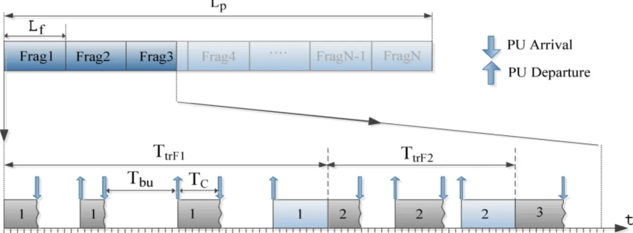
4.1.1 Fragmentation . . . 36
4.1.2 Traffic Pattern of Primary Users . . . 38
4.1.3 Average Successful Packet Transmission Time . . . 38
4.1.3.1 Determination of TC . . . 39
4.1.3.2 Determination of Tbu . . . 41
4.1.4 Packet Dropping Time . . . 42
4.1.5 Average Successfully Transmitted Data Fraction . . . 42
4.1.6 Energy Efficiency . . . 42
4.2 Simulation Results and Model Validation . . . 43
5. DFD-MAC: PROTOCOL DESCRIPTION AND PERFORMANCE ANALYSIS . . . 48 5.1 Protocol Description . . . 48 5.1.1 Path Establishment . . . 49 5.1.2 Data Transmission . . . 49 5.1.3 Protocol Features . . . 50 5.2 Protocol Modeling . . . 51 5.2.1 Derivation of DTMC’s Unknowns . . . 56
5.3 DFD-MAC Performance Analysis . . . 60
5.3.1 Performance Metrics . . . 60
5.3.2.2 TC. . . 61 5.3.2.3 TS0 . . . 62 5.3.2.4 TC0 . . . 65 5.3.2.5 TI . . . 67 5.4 Model Validation . . . 67 6. CONCLUSION . . . 72 7. R´ESUM´E . . . 73 7.1 Introduction . . . 73
7.1.1 La Technologie Full-duplex et la Radio Cognitive . . . 74
7.1.2 FD et la Couche Contrˆole d’Acc`ess au Support (MAC) . . . 75
7.1.3 Packet Fragmentation de la Radio Cognitive Full-duplex . . . 76
7.1.3.1 Fragmentation . . . 76
7.1.3.2 R´esultats de Simulation et Validation de Mod`ele . . . 80
7.1.4 Le Protocole DFD-MAC . . . 81
7.1.4.1 Analyse de Performance du DFD-MAC . . . 84
7.1.4.2 Validation du Mod`ele . . . 85
LIST OF TABLES
Table Page
4.1 Simulation Parameters. . . 44 5.1 Simulation Setup . . . 68
LIST OF FIGURES
Figure Page
1.1 Self-interference in a full-duplex transmitter. . . 1
1.2 Different advantages of the FD technology. . . 3
2.1 The CRAHN architecture and the cognitive radio cycle are shown in (a) and (b), respectively [5]. . . 6
2.2 Two-state transition diagram for modeling the dynamic behavior of primary users over a channel. . . 9
2.3 The IEEE 802.11 channel access mechanism [6]. . . 20
2.4 Proposed 2-D DTMC in [7] for the modeling of the DCF mechanism. . . 21
3.1 Three methods of self-interference cancellation in the FD transceiver [1]. . . 23
3.2 Transmitter and receiver antennas arrangement producing null point [2]. . . 24
3.3 Detailed diagram of FD transceiver equipped with three methods of cancellation [2]. . . 27
3.4 OFDM FD transceiver and different antenna placements for this system [3]. . . 28
3.5 Full-duplex packet exchange of the MAC proposed in [2]. . . 29
3.6 Contra Flow MAC protocol data exchange format [4]. . . 31
4.1 Packet fragmentation and its transmission on the channel. . . 36
4.2 A collision situation. . . 39
4.3 PU interference time, Tint, in HD and FD systems. . . 45
4.4 Average data fraction that is successfully transmitted over the channel before the first PU arrival, FT. . . 46
4.5 Packet successful transmission time Ttr: HD vs. FD with or without fragmentation. . . 46
4.6 Energy efficiency ρ for data lengths of 2000 and 7000 bytes: HD vs.
FD with or without fragmentation. . . 47 5.1 The protocol timing and FD operation when a data packet progresses
in four hops contending for channel access only once. . . 50 5.2 The ability of the proposed protocol to refine the route assigned by
the network layer. . . 52 5.3 The proposed DTMC characterizing the dynamics of the DFD-MAC
protocol at each node. . . 55 5.4 Different placement possibilities of a hearer node (A) w.r.t. a
forwarding path. . . 63 5.5 Node A different placement to a path and hearing one, two or three
nodes of that path. . . 65 5.6 Path delay of DFD-MAC and 802.11 CSMA/CA for different
numbers of neighbour nodes. . . 69 5.7 Path throughput of DFD-MAC and 802.11 CSMA/CA for different
numbers of neighbour nodes. . . 69 5.8 Comparison of DFD-MAC transmission probabilities (τ1, τ2, τ ) with
the transmission probability of CSMA/CA. . . 70 7.1 Fragmentation des paquets et sa transmission sur le canal. . . 76 7.2 Une situation de collision. . . 78 7.3 La fraction des donn´ees moyenne qui est transmise avec succ`es sur le
canal avant la premi`ere arriv´ee d’PU, FT. . . 80 7.4 Rendement d’´energie pour les longueurs de donn´ees de 2000 et 7000
octet; HD contre. FD avec ou sans fragmentation. . . 81 7.5 Le plan de transmission de DFD-MAC. . . 82 7.6 Le retard du chemin dans DFD-MAC et 802.11 CSMA/CA pour des
nombres diff´erents de noeuds voisins. . . 85 7.7 Le d´ebit du chemin dans DFD-MAC et 802.11 CSMA/CA pour des
CHAPTER 1
INTRODUCTION
While the amount of data traffic in wireless systems is developing globally, it is significant to find new solutions in utilizing the wireless spectrum more efficiently. Right now, bidirectional transmission is only possible through time or frequency divi-sion duplexing, meaning that the transmisdivi-sion and reception must be done at different times or over different frequencies. Although Single-channel full-duplexing where a transceiver is able to transmit and receive at the same time and over the same fre-quency channel is yet in its infancy period, it can be a good solution for the high traffic future of telecommunication networks.
Full-duplex (FD) technology has big promises for the telecommunication stan-dardization bodies, industries and research communities that believe in the cognitive radio as the prominent technology of tomorrow. FD has long been an engineering and scientific problem and no practical design for FD system has been proposed until recently with the fundamental progresses evidenced in hardware domain and signal processing techniques.
Figure 1.1: Self-interference in a full-duplex transmitter.
In fact, the reason behind all the early failures in the real implementation of this technology is principally tied to the problem of “self-interference.” Technically,
the difficulty in dealing with self-interference, which is caused by the infliction of interference from the transmitter of an FD station to its own receiver (Fig. 1.1), is not even comparable with cross-interference caused by other nodes, due to the immensity of its magnitude. This is because of the fact that the amount of interference is classically known to be inversely proportional to some exponent (greater than 2 according to the Friis law of attenuation) of the distance between the receiver and the transmitter. Since the FD station’s transmitter and receiver are placed in close distance to each other, the RX signal is going to be completely submerged under the station’s own transmitter interfering power, as shown in Fig. 1.1.
To tackle the self-interference problem, the classic solution is to turn off the station’s transmitter when its receiver is on, and vice versa. This mode of oper-ation, termed half-duplexing (HD), though it decreases the spectral efficiency and transmission throughput, has been the only practical possibility as it avoids the self-interference problem by sharing the time to alternating transmit-receive subintervals. As opposed to this approach, early implementations of the FD technology enabled the simultaneous sending and receiving at a station but over different frequency chan-nels. Recent advancements made it possible to realize highly efficient and strong self-interference cancellation techniques in the analog, digital and hardware domains, which finally led to the fabrication of a successful prototype of FD enabled radios [3]. With this fundamental approach, FD over the same frequency channel (as opposed to different channels) has become possible.
An efficient realization of FD technology can bring chief advantages to communi-cation systems as follows [8]:
• Capacity Enhancement: The spectral resources in the FD transceiver are fully exploited both in time and frequency, and this brings the system a doubled capacity enhancement compared to HD.
• Providing the opportunity of proposing new channel access mechanisms: The ability of transmitting a data packet and at the same time listening to the channel in FD transmitter increases the transmission probability and packet collision detection probability. This can also be a chance for proposing new channel access mechanisms that are more efficient than the currently available protocols used for HD.
• Delay and throughput improvement: FD technology equips the transmitter with the capability of overlapping the data and control packets’ transmission and reception periods, thus reducing the transmission delay while enhancing
Figure 1.2: Different advantages of the FD technology.
• Network fairness progress: The network fairness can be improved in many types of FD networks such as centralized networks. In HD centralized networks with n subscribers, all nodes including the access point (AP) get the same share of the channel, which is equal to n+11 . However, since the data load of AP is n-times more than a regular node, the channel fairness is not the same for all nodes. Using FD technology, the AP is able to transmit at all the times concurrent with the transmission from other nodes, as illustrated in Fig. 1.2(a).
• New relaying strategies: The FD technology transforms the shape of the coop-erative communication by empowering relay nodes to start forwarding a packet upon receipt of the header without needing to wait for the reception of that packet to be completed first. This brings a magnificent amount of advantages to the current and future relaying strategies. (Fig. 1.2(b) and (e)) resolves many existing problems and challenges.
• Lessening the hidden terminal problem: As mentioned before, FD enables the wireless nodes to transmit and receive at the same time. The hidden terminal problem as depicted in Fig. 1.2(c) is a negative topological by-product of almost all multi-hop communication scenarios that sometimes becomes the dominant source of error and packet loss in the network. The problem arises when the receiver station (AP in the figure) is exposed to another station transmission (Node 2) in addition to the the transmitter station’s (Node 1) signal. Using the FD technology, the receiver can signal a constant busy tone (or any other data packet) which informs other nodes in the network of the current busy channel
status, which ultimately prevents the hidden terminal downsides from harming the communication and diminishes the collision probability in turn.
• Security improvement: From the point of an attacker view who wants to eaves-drop two FD nodes’ transmissions, at each instance of time, he/she encounters a scrambled signal that is a blend of two different signals on a single chan-nel, which cannot easily be separated with no side information. As a result, transmission security is naturally enhanced as illustrated in Fig. 1.2(d).
Having summarized the main advantages of the FD technology, in the next chap-ter, we present a background on the cognitive radio (CR) and medium access layer. Then in chapter 3, we provide a literature review on the physical and MAC layers of FD systems and we show how researchers could overcome the self-interference prob-lem and turn the dream of having FD transceiver into reality. This thesis focus being realizing the benefits that FD technology can bring to the regular wireless systems, in chapter 4 we show how equipping the network nodes with FD transceivers and applying a suitable channel access mechanism can decrease the hidden terminal prob-lem and increase the opportunity of establishing successful transmissions. We also demonstrate that this characteristic of the FD technology plus the ability of having simultaneous transmissions and receptions can make a noticeable improvement in the capacity, throughput and delay in the considered networks. Subsequently, we study a FD cognitive radio network in chapter 4 and apply packet fragmentation in the MAC layer of the secondary user to reduce the packet drop rate and the primary’s interference time while improving the energy efficiency at the same time. Finally, the thesis is concluded in the last chapter.
CHAPTER 2
BACKGROUND INFORMATION
At the beginning of this chapter, we give a brief review on cognitive radio networks and their famous MAC protocols (section 2.1). Then, we review different types of MAC protocols in wireless local area network (WLAN) and the main methods used in the performance analysis of these protocols (section 2.2). At the end, we explain the IEEE 802.11 distributed coordination function (DFC) and Bianchi Markov modeling in more detail. Since, in section 5.1, we use the Markov chain as the modeling tool for our proposed FD MAC and our model has similarities with the main model proposed for the CSMA/CA about a decade ago, we explain this latter model for a better understanding of what comes in later chapters.
2.1
Cognitive Radio Networks
With the continuously increasing demands for high-bandwidth wireless applica-tions, the current rigid frequency allocation will undoubtedly fail to meet the future needs. However, thanks to the measurements made, which showed that large frac-tions of the spectrum are not efficiently utilized [30], cognitive radio (CR) is paving the way for an efficient access to the spectrum holes when identified by the cognitive users.
2.1.1 Functional Blocks
The term CR [30], [31] refers in essence to the technology that enables a wireless station to adapt itself to the changing wireless environment. This definition simply attributes two key features [31], [32] to the CR technology, meaning vigilance and adaptability. The wireless vigilance demands that CR-enabled stations be able to discover the characteristics of the wireless environment such as the available spec-trum holes, the interference level, etc., through a combination of techniques at the center of which the sensing is located. On the other hand, the adaptability is the ability of the wireless stations to constantly adapt their transmission characteristics effectively using the information gathered by the vigilance feature. These transmis-sion characteristics can span anything from the modulation type and coding rate, to
the center frequency, transmit power, antenna directivity and so forth and therefore is a general notion [33]. In a finer classification [34, 31, 35], four sets of tasks are defined for a cognitive platform: (1) Spectrum sensing (2) Spectrum decision, (3) Spectrum sharing and (4) Spectrum mobility.
It should be noted that while this spectrum-centric definition of CR with the classification given above does not govern the general definition given before, it is sufficient to solve the problem of inefficient allocation of the spectrum explained before. These functionalities are shown as modules below in Fig. 2.1 and explained one by one in the following subsections.
(a) Cognitive1a (b) Cognitive1b
Figure 2.1: The CRAHN architecture and the cognitive radio cycle are shown in (a) and (b), respectively [5].
2.1.1.1 Spectrum Sensing
Due to the fact that in DSA the exclusive right of access does not exist anymore, any station can occupy a wireless channel. However, for this mode of operation not to turn into chaos where the simultaneous transmissions from different stations result in an unacceptably high level of interference, a sensing mechanism is required to detect the presence/absence of the licensed (PU) transmitters. Therefore, wireless nodes transmit on a channel only if that channel is empty at that moment.
Over the course of years, different sensing mechanisms have been proposed with their deficiencies and strength points. Perhaps the most common technique among all is the energy detection method where the receiver intermittently collects samples from the receiver antenna and averages them for a period of time (sensing interval),
the air or the channel is empty. It is well-known that the energy detection method is easy in implementation though it is mixed with uncertainties and performance chal-lenges rendering it inefficient in some situations. Later on, other reliable techniques were introduced that induced more complexity into the system but outputted a more reliable decision. Just to name a few, we can mention the cyclostationary detection method and the matched filter detection method.
The important point to take into account here is that the recurrent behavior of PUs on channels, which is prompted due to their exclusive access right, calls for the periodic sensing of the channel or channels that the SU is willing to opportunistically get access to. Defining the sensing period as the interval between launching two sequential sensings over the channel(s), the first things crossing one’s mind is that the sensing period shall neither be very short nor very long, as it causes a high chance of interference or it wastes the resources, respectively.
The sensing reliability, which plays an imperative role in the amount of interfer-ence inflicted to PUs, can be increased through other methods rather than decreasing the sensing period and increasing the sensing interval. One of these methods is called cooperative sensing. In cooperative sensing, stations that can either be organized in centralized or decentralized settings collaboratively conduct the sensing task and share the sensing decision outcomes with each other. Without going to much in the details, one should just bear in mind that cooperative sensing improves the sensing reliability by some factors depending on the location and the number of the col-laborators and that it follows the same logic as in cooperative communication (i.e., cooperative diversity).
2.1.1.2 Spectrum Decision and Spectrum Sharing
After the sensing mission is carried out, stations should be able to transmit their traffic. For the case of single-channel CRN, the determination of the presence or absence of the PU simply boils down to a binary decision made by SUs on whether they can transmit on that channel or not. However, the single-channel scenario is only a simplification of the notion of CR since CR is supposed to help in collapsing all the existing rigid boundaries, which can span several Gigahertz of spectrum. Therefore, as an ultimate target, wireless stations ought to be able to monitor a wide width of the spectrum to discover all the holes and decide between them. This decision shall be optimal considering many factors from the activity pattern of PUs to the changing wireless conditions. For example a rational choice for a SU would be to choose bandwidth for transmission that has the least PU activity pattern and has experienced the least number of deep fadings (largest SNR). In a more advanced level, such a decision can even be made in a global manner so that the network optimality
is achieved by asking stations to distribute the available pools of resources in such a way, e.g., the network throughput is maximized. Therefore, the problem of allocating the resources among nodes is actually transformed to an optimization problem where the constraints are set, and the objective is to redistribute the available resources among the stations in a locality in such a way that the maximum payoff (minimum cost) is achieved. In fact many game-theoretic and optimization studies have targeted this problem recently and many interesting results were obtained. This is however beyond the scope of this thesis.
2.1.1.3 Spectrum Mobility
Due to the non-exclusive access of SUs to the spectrum and, conversely, the exclu-sive right of PUs to access the spectrum whenever they have a traffic for dissemination, SUs are exposed to unpredictable interruptions of connections and collisions caused by the recurrence of PUs over the channel. As we introduced just before, the intermit-tent sensing by a SU helps the latter maintain its vigilance of the semi-instantaneous situations on the channel.
The spectrum mobility deals with the ability of SUs to keep up the quality of their logical link after the recurrence of PU to that channel is assured. Apparently, a handoff mechanism is required in order to shift the communication link to another physical channel. This indicates that a list of backup channels is necessary to be kept all the time and frequently gets updated by all the SUs for such situations. Spectrum handoff usually incurs a loss, which its severity depends on the agility of the handoff mechanism and some other factors.
In a different viewpoint, likewise other networks where the centralization of access is a key factor in classifying the emerging technology, the CRNs can be of two types [34]: (i) Infrastructure-based CRNs and (ii) CR ad-hoc networks (CRAHNs).
As its name implies, in infrastructure-based CRNs, a central entity generally called base station (BS), is in charge of the aforementioned cognitive tasks. Since the ex-ecution of the tasks that a cognitive node needs to carry out is enormously large, a central element such as an AP with presumably unlimited processing and communi-cation power sounds more feasible in many applicommuni-cations. Nevertheless, akin to other networks, the centralized approach suffers from a lack of scalability and robustness, and thus can’t be the only conclusive option. On the contrary, in the decentralized CRAHNs, no central element exists and stations are responsible for the aforemen-tioned cognitive tasks in self-autonomous or cooperative manners.
2.1.2 Traffic Modeling
There is no doubt that the very precise determination of the traffic pattern (or activity pattern) of PUs over a channel is extremely difficult and a cumbersome task and that it can not be done in a modeling framework. In fact, in actuality, PUs represent digital TV operators and wireless microphone users, etc., with different traffic patterns and transmit powers. In rare situations where some PUs’ activities follow a deterministic pattern, SUs can exactly determine the presence/absence time of PUs. However, in most of the cases, the behavior of PUs is unpredictable and seen like a random process from SUs’ perspective. Hence, statistical metrics are the only tools that can be used to characterize and capture their behavioral trends. Such statistical metrics, which are obtained by time-averaging of many empirical observations, are mainly abstracted in the form of average and variance and sometimes higher moments. For the problem at hand, it turned out that average activity pattern is an important indicator reflecting the chief statistical properties of the PUs. This activity factor simply reflects what fraction of a time interval is in average occupied by a PU. The larger this figure is, the more occupied the channel is perceived to be. The mathematical logic behind the representation of the traffic pattern using a single number is shown in Fig. 2.2 where the activity pattern of a PU is shown by a two-state birth-death process. As illustrated in this figure, state I represents the absence of PU on the channel while state B shows its presence. The transitions between these two states are extended using fixed probabilities P0 and P1. Since the dwelling times in the states of a birth-death process are exponentially distributed, it is easy to find the steady-state probabilities of being in idle and busy states in this diagram based on the given transitions probabilities. If solved, the probability of being in a busy state would be equal to the activity factor that we introduced before.
Figure 2.2: Two-state transition diagram for modeling the dynamic behavior of pri-mary users over a channel.
To solve this diagram, the values of P1 and P0 are required. These values can be obtained through experimentation by sensing the channel and counting the number of times the channel goes from busy to idle and, separately, from idle to busy and dividing each count by the total number of changes (either way). Many studies took
the above model as the baseline of their investigation as a well-established model [36, 37, 38, 39, 40, 41]. Therefore, when needed, we take this model for modeling the PU activities in this thesis as well.
2.1.3 Medium Access Layer in CRNs
Medium access layer in CRNs is of more importance compared to its counterpart in other networks due to the undertaking of the four cognitive tasks introduced briefly in the last section. Though the investigations in recent years resulted in different classifications of MAC protocols suitable for different situations, the classification by the centralization/decentralization of data and sensing planes is of more importance; for example, a combination of CRAHN with a centralized sensing scheduling, where a central element exists to optimally choose the sensors and sensing parameters, makes a perfect sense for a reliable PU protection. The choice of sensing parameters such as the sensing periodicity, sensing length, number of sensors, sensing threshold, sensing type, etc. results in totally different MAC protocols. Here we start by introducing the existing cognitive MAC protocols as follows.
2.1.3.1 Random Access CR MAC
Due to the fact that the contribution of this thesis is on the medium access in FD enabled radios, it is mandatory to give an introduction on the existing major classes of MAC protocols. However, since the target network in this thesis can be cognitive-enabled or not, we start with the introduction of the cognitive MAC protocols, as this will govern the classical MAC protocols as well.
• Single Interface: Decentralized or random access MAC protocols are suitable for networks where no infrastructure exists and synchronized operation can’t be achieved. Due to its popularity and its well-adopted functionality, many of the random access CR MACs are built upon the CSMA/CA access mechanism with enhanced capabilities to be adaptable for CR operation. The self-autonomous behavior of a station liberates it from any reliance on external aids and the station is responsible for all the decisions. For example, one of the important decisions of a station in the decentralized mode is to figure out what portion of the resources (i.e., power, bandwidth, etc.) should be allocated for the sensing and what proportion should go for the data transmission. This problem was proposed in [42] with the name of hardware-constrained MAC (HC-MAC) by obtaining the optimal length of the sensing interval. In this protocol, a common control channel (CCC) is dedicated for channel contentions after which the
two CR nodes situated at the ends of a link is determined, this list is distributed in the form of a control massage the loss of which is a challenging problem by itself. In the single-radio adaptive channel (SRAC) MAC protocol [43], the presence of jammers in the CR frequencies were considered.
• Multiple Interfaces: When there is the possibility of equipping stations in the CRN with multiple interfaces, a more reliable communication can be expected. In fact, the two chief problems that substantially deteriorate the performance of random access schemes are the hidden and exposed terminal problems [44, 45]. By exploiting several interfaces, these problems can be alleviated to a large extent. For example, in dynamic open spectrum sharing (DOSS) MAC protocol [46], stations are equipped with three transceiver interfaces for control, busy-tone and data transmission purposes. The protocol is designed in such a way that a mapping exists between the data channels and the busy-tone channel, meaning that when a station obtains access to a channel (say ch. i), a busy tone is emitted on a corresponding frequency in a busy-tone band as well in order to notify all other nodes of the occupancy situation. Therefore, the serious problem of missing the control channel associated with [42] can be avoided. Moreover, the existence of a busy-tone band allows the other nodes to more efficiently perform the sensing tasks by only sensing the channels that do not have a triggered busy-tone signal (flag) in the corresponding busy-busy-tone band. Therefore, transmissions from SUs are not mistaken for those of PUs. Nonetheless, it is obvious that the installation of three transceivers and dedicated control and busy-tone channels are among the incurred costs of this scheme (protocol).
2.1.3.2 Time-Slotted MAC
These MAC protocols require network-wide synchronization where the time axis is split into time slots for the control and data channels [47, 48]. For instance, in the cognitive MAC (C-MAC) protocol [47], which has much similarity with IEEE 802.22, distinct slots are allocated in the beacon period to each cognitive node.
Taking the famous C-MAC as the pivot of discussion, this protocol determines the best existing channel according to the information in the beacon, named the rendezvous channel (RC), and a list of backup channels (BCs) that may be used as in reserve. The RC is then used as the control channel, which is different from the data transmission channels. Likewise for IEEE 802.22, the transmission units on the data transmission channels are called superframes comprising three major sub-periods named data transfer period (DTP), beacon period (BP) and quiet period (QP). The BP and QP are not necessary synchronized for different channels. This permits the
other cognitive stations to distribute their local information using beacons in addition to enabling truthful sensing operations in the QPs. The cognitive nodes intermittently check RC to get the local information about neighbors, do the synchronization and declare any state-change in the spectrum.
2.1.3.3 Hybrid MAC
The hybrid MAC protocols are designed to bring together the advantages associ-ated with the decentralized and centralized access methods. This means that though the control signaling takes the centralized approach through the transmission over the synchronized time slots, the data transmission is done in a random access fashion or vice versa.
Among many proposed protocols, we can name [49, 50, 41]. In Cog-Mesh [49], the cognitive nodes are bundled into clusters where two types of communications are required: intra-cluster and inter-cluster. In intra-cluster communication, the beacon packet exchange, the neighbor list maintaining, and the data transmission are all carried out by the cluster heads. In inter-cluster communication, the cluster heads accept new CRs soliciting to join the network as well as undertake the data routing among themselves. A similar approach was taken in opportunistic spectrum MAC (OS-MAC) protocol [50]. However, the problem associated with any clustering-based MAC architecture is directly related to the overhead of forming the clusters and maintaining the connectivity in the presence of station mobility.
In the partially observable Markov decision process (POMDP) MAC protocol proposed in [41], cognitive nodes perform both the data transmission and the sensing task within a time slot. More interestingly, the data transmission mode is the same as the RTS-CTS scheme in the CSMA/CA access mechanism. The point of departure of this protocol pertains to the learning mechanism that assigns different weights to channels. This gets accomplished by successively assigning awards (weights) to channels that just carried a successful transmission. The protocol also optimizes the length of sensing time in each slot, which directly enhances the network throughput. There are some problems associated with this protocol as well, such as its reliance on the assumption of constant PU arrival rate (time invariant pattern), inefficient start-up phase, etc.
2.2
Wireless MAC Protocols
Simply speaking, the main task of the medium access protocol in the MAC layer is to schedule the network access of stations. This includes instructing nodes when to access the shared medium and using how much of the resource and in what way
to do it. The channel access assignment must be in a way that the limited network resources could be fairly and effectively shared among stations [51]. In fact, designing a suitable MAC protocol according to the characteristics of the network and also its physical specifications is important in achieving the highest system performance.
According to [52], one general classification of MAC protocols is: random access, guaranteed access and hybrid access. The random access protocols such as ALOHA [53], Slotted ALOHA [54], CSMA (non-persistent, p-persistent and 1-persistent) [55] and CSMA/CA perform based on wide network contention between stations without the need for a BS to share the channel access opportunity among the stations. Thus, the back-off strategy in such protocols is essential and helps the system avoid colli-sions. In fact the scheduling in these protocols is obtained by the randomization of access instants.
On the other hand, in guaranteed access, the channel access assignment is done either by polling or token exchange. The polling protocols work in the master-slave form where the master node polls the slaves and in return the slave nodes send their data to the master. In the token-passing protocols, a token packet passes among the nodes and only the node that has the token is authorized to transmit its data to the BS. After the data transmission, the token will be send to the next station.
Finally, the hybrid access mechanism is a combination of the two above-mentioned methods to take advantage of both [52]. Here, using the random access mechanism, stations solicit channel access by sending access requests to the BS or AP (decen-tralized soliciting). When the AP receives such requests, it decides either to accept or refuse them. Upon acceptance, the BS assigns time slots to the corresponding stations and sends control messages back to these stations providing each of them with information about its assigned time slot (centralized access). Once the time slots assigned to a group of nodes, the following transmissions would be collision-free. This protocol is usually used in multimedia applications since it provides a high level of Quality of Service (QOS).
Speaking of random access protocols, we should also mention that these protocols are flexible and robust in nature and because of that, they can be reliably exploited in distributed access networks or in the hybrid schemes. In addition, random access pro-tocols can easily incorporate some mechanisms to provide prioritized channel access to different stations [56], which is indispensable for a network’s service differentiation. While the suitable MAC protocol can guarantee high performance of the wireless network, it’s important to fully understand the characteristics of the MAC protocol we are going to use in a system. In this thesis, our focus is on the CSMA/CA protocol. To that end, in the next section, we give a brief explanation on different existing models that emerged to analyze the performance of the distributed MAC protocols.
The focus is only on distributed MAC due to the fact that the MAC protocols that we will introduce in Chapter 4 and 5 for FD enabled radios are of distributed nature as well.
2.2.1 Analytical Models for Distributed MAC Protocols
The performance of MAC protocols can either be analyzed using simulations or analytical models. However, the problems associated with the simulation approach are time-consuming and its limited validity to the set of parameters under investigation. On the other hand, the analytical models can help us take a deeper look into the features of the protocol as they are not merely valid for a single set of parameters (and if they are, the model is not good and should be revisited and reinvented.)
Concentrating on the analytical models, in general there are three approaches taken to evaluate the performance of MAC protocols. All three are basically stochastic models but with different statements and approximations. These protocols are briefly explained below.
2.2.1.1 S − G Analysis
From 1970 to 1990, this model was the main approach of analyzing the perfor-mance of slotted and non-slotted protocols such as ALOHA and CSMA [55, 57, 58, 59, 60, 61, 62]. In this approach, S stands for the carried load and G represents the offered load [63]. Here the chief assumption is having an infinite number of nodes producing a traffic alike an independent Poisson source with a cumulative rate of S packets per slot. Also, the aggregate transmissions and retransmission traffic are modeled by a Poisson process with the transmission rate of G packets per slot [59]. In fact, it was proven later that the limitation of this model is related to the crude assumption of having an infinite number of nodes and a one-word size buffer for each station. Moreover, this model is more applicable to homogenous networks.
2.2.1.2 Equilibrium Point Analysis
The performance evaluation of the MAC protocols gets complicated in the Marko-vian models especially when the number of working states increases (e.g., when the back-off stages and queue length both increase at the same time). However, by using an equilibrium point analysis (EPA), any complex steady state Markov chain can eas-ily be approximated. As apparent from its name, the EPA is a model for the steady state operating point of a system that uses the fluid-type approximation [59, 64]. In this model, the main assumption is that the system is always at equilibrium. In other words, the traffic entering into a state at the equilibrium point is equal to the traffic
leaving that state. Thus, we can find a set of nonlinear (mostly) equations whose solution will give us the value of the equilibrium point. The main advantages of this protocol is that it is not necessary to calculate the state transition probabilities of the Markov chain and that is the reason why this approach can be used in analysis of complicated MAC protocols such as the packet reservation multiple access (PRMA) protocol.
2.2.1.3 Markov Analysis
Perhaps, the Markov chain is, by far, the most prominent tool for the analysis of MAC protocols. This tool is used in two main directions. The first direction is to use a Markov chain to model the states of the system. In [65] and [66], a MAC protocol has been considered for a homogenous network with the following states:
• State I - backlogged state: in which the frame should wait in the buffer for its turn to be transmitted.
• State II - thinking state: with no frame waiting in the buffer and based on the Bernoulli distribution, a frame is generated and added to the buffer later on. In this model, a one-dimension Markov chain is used where the number of backlogged stations represents each state of the chain and obviously the number of states is equal to the number of stations. This is the simplest form of Markov analysis for MAC protocols. The multi-dimensional Markov chains are used for the more intricate protocols. For example, for the case of multi-stage back-off mechanisms, each state might represent the number of stations in a specific back-off stage [67]. Another example is the modeling of the network with multiple classes of stations. In this situation, each dimension of the Markov chain represents the number of nodes in each class (e.g., [68] for integrated voice and data system with PRMA [69]).
A different well-known approach to be taken for the analysis of networks is to use Markov chains for the modeling of the buffer status in each node, a good example of which is [63]. Nevertheless, this exploitation of Markov chains for large buffer sizes is very tedious and practically works for situations with small buffer sizes. Up to this point, the usage of Markov chains in the network level was discussed. In other words, rather than representing the number of stations, etc., states of a Markov chain might represent the states of an individual station in the network. This usage of Markov chains found popularity specifically after the studies of Bianchi in [70, 7] on the performance analysis of DCF in the IEEE 802.11 WLAN standard. In simple language, here the value of a back-off counter of a station at any instant of time represents a state of the Markov chain and the inter-state transition occurs once
the back-off counter reduces or a retransmission is initiated. More details on this modeling approach will be provided in the next section.
Numerous analyses have been proposed on the modeling of the DCF mechanism grounded mainly on the Markov model of Bianchi, but entail more practical aspects of the standard (e.g., [71, 72, 73, 74, 75]). Bianchi’s model was generic enough that it was even used to model other offspring protocols such as IEEE 802.11e enhanced distributed channel access (EDCA) (protocol designed to handle servicing multiple classes of traffic by prioritization) [76, 77, 78, 79], IEEE 802.15.4, which is aimed at personal wireless communication (a basis for the Zigbee protocol) [80, 81, 82, 83] and HomePlug [84, 85].1
Though the outputs of the Markov models introduced right before are in good conformity with the experimental data, there are some issues of precision that need to be mentioned here. In fact, one of the reasons that renders any Markov model an approximate approach is due to the memoryless assumption that is associated with it. The memoryless property in the above models attributes itself to the Poisson and Bernoulli assumptions of traffic sources and the saturation assumption (meaning the station’s buffer is always non-empty). Nonetheless, even with such simplifying assumptions, the complexity of the model for a high number of states is sometimes enormous and finding a transition probability matrix and the state transition proba-bilities is yet a cumbersome task.
2.2.2 IEEE 802.11 Distributed Coordination Function MAC protocol The MAC layer in IEEE 802.11 comes in two different flavors, DCF and point coordination function (PCF), where the PCF [86, 87] was embedded as an alternative access mechanism to handle real-time traffic using a centralized polling mechanism. The main reason for the pervasive popularity of WLANs is due to the proved success of the DCF mechanism. In fact, the popularity that DCF has obtained is not even comparable with that of PCF, which is not as efficient as its rival, has limited QoS provisioning, and bears a lot of complexity in implementation [88].
1HomePlug is the name for different types of power line communication technology over the house
electrical wiring. The random back-off algorithm in CSMA/CA IEEE 802.11 has been used as the mechanism of accessing the channel to avoid collision between different nodes’ packet transmission. [85]
2.2.2.1 DCF Access Mechanism
In the DCF access mechanism, stations compete with each other to grasp the channel access. The basic rule of this mechanism is that stations must sense the channel before initiating transmission. Due to this reason, the name of this mechanism is carrier sense multiple access with collision avoidance (CSMA/CA). When a station has a packet to transmit, it first senses the channel and if there is no activity on the channel, it can initiate transmission. However, if it finds the channel busy, it will defer its transmission for a random amount of time. This random time (call it back-off) is extracted from a uniform distribution with range [0, CWr), where the value of the upper bound CWr is to be updated (in fact, increased) after each unsuccessful transmission. A station is not allowed to transmit until its back-off counter is zero. This demands that back-off counters of awaiting stations are reduced as follows: A back-off counter is reduced by one unit at the end of every idle time slot (an empty channel) and is frozen to its current value (a busy channel) for the duration of channel business. This requires that stations be vigilant of the channel status in all the time slots in order to obey this back-off decrement procedure.
The continuous sensing of a channel imposes a great deal of power and processing expense on stations, which is not desirable at all. As a matter of fact, it was proven experimentally that the amount of power that is required for sensing the channel is quantitatively alike to transmit power, a fact that renders continuous sensing an inefficient approach. In order to avoid this problem, a small twist was introduced in CSMA/CA, called the network allocation vector (NAV). Simply speaking, NAV is an information vector that is embedded in the transmitted packet and includes the remaining length of the current transmission (in bits or bytes). This vector is embedded at the beginning of ready-to-send (RTS), clear-to-send (CTS) and data packets, and simply notifies awaiting stations of the length of the time that this transmission will go on. Upon receiving the NAV, a waiting station (stations with non-zero back-off) will freeze the back-off counter and turn off its sensing module for the duration of overheard NAV and will eventually come alive once this duration is expired. This mechanism clearly helps a lot in diminishing the power consumption.
Upon expiration of NAV, the station senses the channel again; if no transmission is detected, the back-off counter decreases by one if the station finds the channel idle for the duration of DCF-interframe-space (DIFS) (usually, a few times the slot length); otherwise, the previous freezing procedure gets repeated. Since the channel activity seen from an observer’s point of view is an infinite sequence of busy/idle states, the decrement procedure will reach zero at some point, which makes the station eligible to transmit.
Though the randomization obtained by the back-off mechanism diminishes the collision probability by many orders of magnitude, there still exists the possibility of collision that occurs when two or more stations finish their back-off counters at the same time and thus transmit in the same time slot. Therefore, it is mandatory that the receiver acknowledges receipt of the packet to the transmitter by a short ACK packet transmitted after a short interval, namely the short interframe space (SIFS). If the transmitter receives the ACK packet within a predefined interval (ACKT imeout), a new contention for the next packet in the buffer will be initiated; otherwise, the station initiates the retransmission of the packet by doubling the contention window CWr, extracting a back-off number, and the rest is the same as what explained so far. In the meantime, how many times a packet is allowed to be retransmitted depends on the traffic, QoS requirements and the choice of other network parameters. For a packet that is allowed to be transmitted m times, if the number of retrials approaches this number, the packet will be dropped without having a chance for future retransmissions and the contention procedure for the transmission of the next packet in the buffer.
Speaking of collision, it is important to know that, though the collision event (attributed to a collision probability) in a nominal network is a rare possibility, the seriousness of this event is affected by the choice of parameters, and particularly the number of contending stations. The choice of contention window length CWr that was discussed before is one of these parameters where a larger value for this parameter makes the collision probability smaller. Normally, the initial value of a contention window is CWmin = 32 and it can increase until CWmin = 1024 (i.e., m = 5 retransmissions are allowed).
Finally, there are two modes of transmission defined in IEEE 802.11 DCF that differ in what comes after a node wins the contention and transmit, namely RTS/CTS mode and the basic access mode. In the RTS/CTS access mechanism, the winner of the contention transmits a control packet called RTS to the receiver before transmit-ting the data packet as illustrated in Fig. 2.3. Once the receiver receives this RTS packet, it will reply by transmitting back another packet called CTS. If the receiver receives the CTS packet and was able to decode it correctly, it assures that no col-lision has taken place and therefore the data transmission commences. Otherwise, the collision flag goes up like before, and the same contention procedure starts again. On the contrary, in the basic access mode, the contention winner transmits the data packet immediately after winning the contention and no control packet, RTS or CTS, is exchanged between pairs.
Though the exchange of RTS/CTS control packets between transmitter-receiver pairs for every single transmission incurs a large overhead, it lowers the collision
window by orders of magnitude (in particular, for lengthy data packets) as the case of collision is resolved within the duration of RTS+SIF+CTS.2
2.2.2.2 DCF Modeling
The performance of the 802.11 DCF access mechanism has been analyzed in [7] and expanded in [71] using the discrete time Markov chain (DTMC) tool. This model helps to identify the important quantities such as transmission and collision probabilities, throughput, etc. Since the proposed model for the FD MAC in chapter 5 is built having the Bianchi’s DTMC as the foundation, a detailed introduction to this model will be provided in this section.
A DTMC [89] is a discrete-time stochastic process where the future state of the process depends only on the current state and is independent of the process history. Briefly, the DTMC introduced in [7] is a 2-D stochastic process (s(t), b(t)) in which s(t) represents the retransmission stage in the DCF mechanism and b(t) stands for the back-off time counter in each of these transmission stages. As is known, the back-off counter either counts down at the end of a time slot, if the channel is idle, or freezes its previous value, if the channel is busy. Nevertheless, the busy status of the channel can be either due to the successful transmission or collision from one or more nodes located somewhere in the hearing range of this node. All the waiting nodes persist in hearing the channel and once the channel goes idle again (which happens due to the completion of the preceding transmission), they unfreeze their back-off counters. Since we can’t go deep into the details of access mechanism in CSMA/CA, we refer interested readers to any of the above papers to gain deeper knowledge on the topic. All these reflected as a 2-D DTMC as proposed by Bianchi in Fig. 2.4. All states in such DTMC are non-periodic and non-null, and thus the process is ergodic [89] and a stationary distribution exists.
When the back-off counter of a node reaches zero, the node is eligible to initiate a transmission immediately. If this transmission faces a collision, the packet would be refrained for the next transmission and the node starts a new back-off counting. In fact, at each new stage (retransmission trial) the back-off b(t) is chosen uniformly from the interval [0, Wi], where Wi = 2iW0 for i = 0, · · · , m. Here m is the maximum back-off stage and W0 is the contention window of the node when a packet is going to be transmitted for the first time (stage zero). Considering an infinite number of
2This is an improvement compared to the basic transmission mode where collided transmissions
are not stopped and can prolong for a long time, wasting valuable resources without involved partners knowing of the raised situation.
(a) CSMAacessa
(b) CSMAacessb
(c) CSMAacessc
retransmissions for each packet, apparently after the mth retransmission the back-off length doesn’t increase any more. Of course, there are some assumptions made in Bianchi’s model to make the model analytically tractable; these assumptions have also been made in [90] and are as follows:
• Transmission failures can only be due to the collision of two packets.
• All nodes in the network are in the saturated state, meaning that they always have packets waiting to be transmitted.
• The probability of packet collision is constant in time and independent of the collision history, i.e., the probability of collision is totally independent of the retransmission stages of a node.
• The existence of hidden and exposed terminal problems is neglected.
Having the above-mentioned assumptions in mind, and defining τ as the proba-bility of transmission, then one would simply discover that the probaproba-bility of collision is:
p = 1 − (1 − τ )n−1. (2.1)
Defining P (s(t) = i, b(t) = k) as the time-dependent probability density func-tion (PDF) of being in the state (i,k) in Fig. 2.4, then its corresponding stafunc-tionary distribution would be:
bi,k = lim
t→+∞P (s(t) = i, b(t) = k). (2.2) The transmission probability τ could be derived as:
τ = m X
i=0
bi,0. (2.3)
By applying a little bit of algebra, τ could be derived as
τ = b0,0 1 − p =
2(1 − 2p)
(1 − 2p)(W0+ 1) + pW0(1 − (2p)m)
. (2.4)
In the analysis of CSMA/CA, it’s important to have the numerical value of τ since it is one of the main parameters needed to calculate the throughput, delay and other
CHAPTER 3
LITERATURE REVIEW
In this chapter, we present a comprehensive review on the FD technology litera-tures. We start with the articles proposing solutions for handling the self-interference problem and then we study the existing FD transceivers that have been implemented so far. The proposed MAC protocols will be introduced in the latter section for dif-ferent FD networks and the last part of the chapter presentees a brief summary about the main contribution of this thesis.
3.1
Self-Interference Cancellation Methods
As we mentioned before, combating the self-interference effect is the key challenge in the FD transceivers. In the situation that the wireless nodes are equipped with only one transmit antenna, increasing the separation distance between the transmitter and receiver to reduce the self-interference effect is the most intuitive method. However, the separation distance does not seem practical for different devices with different size and applications. Therefore, other ideas were proposed lately. Fig. 3.1 shows the physical layer of an FD transceiver using three main methods of self-interference cancellation. In fact, a review of the existing literature reveals the following methods using which self-interference cancellation is accomplished.
3.1.1 Antenna Cancellation
The idea of the antenna cancellation method is based upon the fact that a single transmit antenna cannot considerably diminish the self-interference. As a matter of fact, the system operation in high signal-to-noise ratio (SNR) regimes requires that the system limits the amount of interference rather than dealing with eliminating it once it has already been mixed with the desired signal. This understanding helped to enlighten investigations on antenna cancellation methods where two antennas, rather than one, are used at the transmitter side. Indeed, by separating the transmit antennas and splitting the transmit power between them, it was demonstrated that the accumulative field patterns produced are added up constructively in some spots while destructively in other spots in such a way that few null spots are observed. This method is shown in Fig. 3.2. For instance, for the situation of equal split power, these null spots are located on the line connecting the transmitters, where the difference of distances to transmitters is odd multiples of half the wavelength, i.e., ∆d = d2− d1 = (2m − 1)λ/2, m = 1, 2, ... .
Figure 3.2: Transmitter and receiver antennas arrangement producing null point [2].
Thus, by putting the receiver at these spots, considerably less self-interference is experienced. Nevertheless, the number of null spots that exist depends on the distance between the transmitters, and if ∆d < λ/2, no null spot exists. This immediately indicates that one of the limitations associated with the two-antenna cancellation method is the distance. Moreover, this method cannot be feasible when the operating frequency is low (λ is high) since the device size will be a bottleneck. Further to above limitations, this technique is not suitable for wideband signals, as they are composed of many frequency components and thus a null region is required rather than a null spot, if an even cancellation is sought. The other drawback of this approach is the creation of many null spots in the far field, which is not desirable at all. Lastly, as shown in [9], antenna cancellation requires manual tuning, which can’t be an ultimate solution for exploitation in highly varying wireless environments with shadowing, fading, etc. An alternative approach to alleviate these problems would be to use
Hence, the antenna cancellation with three antennas (two transmitters + one receiver) is defeated by the three-antenna multiple-input multiple-output (MIMO) technology [10], as the former doubles throughput while the latter triples the throughput. In [11], the antenna cancellation method was refined to eliminate the far-field null zones. Using a Balun circuit, which creates a π degree phase shift, makes this method independent of the signal wavelength, which comes at the cost of higher hardware design complexity. By implementation of a two-level cancellation, their pioneering design in MIMO FD system is obtained. However, this scheme is only suitable for a communication range less than 3 meters, as evidenced in [11].
3.1.2 Digital Cancellation
This self-interference cancellation method was first used in [12] and then it has been used in [9, 13, 14, 15, 16, 17] . In general, further to its application in FD, this approach has found profound application in optical networks and carrier sense multiple access with collision notification (CSMA/CN) as well. The main idea in this technique is to subtract the fed-back transmitted digital symbols (self-interference symbols) from the base-band received symbols in the digital domain so that a clearer version of the signal is decoded [18, 19, 10].
Traditionally, this method was used to detect the desirable signal collided with a transmission from another node. This was accomplished by detecting the undesir-able signal, re-modulating it, and then subtracting it from the mixed received signal after the analog-to-digital conversion (ADC). In the case of FD, the complication is less as the transmitted symbols are perfectly known in the transmitter and, thus, de-modulation and decoding are not required. Therefore, by coherent detection, the received signal is correlated with the known self-interference. The difficulty in this process is the unknown delay and phase differences of received and transmitted sig-nals, which can be obtained by correlation of these signals and then feeding the phase and delay information to the subtractor.
The block diagram of this method is shown in Fig. 3.3. The empirical results show that the digital cancellation is effective in both high and low signal-to-interference plus noise ratio (SINR) regimes and can cancel up to 20-25 dB of self-interference [15, 16]. The limitation associated with this technique is its sensitivity to the limited dynamic range of ADCs as the self-interference signals are very strong while the received signals are extremely weak making it impossible to recover the digital samples in some situations.
3.1.3 Analog (RF) Cancellation
In this approach, the self-interference cancellation is carried out in the analog domain on the radio frequency (RF) signal before the information is fed into the ADC. The first realization of this technique is to use a second transmission chain to construct an analog cancellation signal from a digital estimate of the self-interference [13], removing self-interference from signals with bandwidth 625 kHz for 33 dB. The other realization is similar to the noise-cancellation in headphones [14]. One way or the other, this goal can be achieved by deploying an RF cancellation chip [20] prior to feeding the ADC with the analog signal. This shows to help reduce the self-interference by 25 dB [14].
An example of this method was implemented by Radunovic et al. [14] who used a noise cancelling chip called QHx220 (Fig. 3.3) to remove the analog interference from signals operating in FD mode in 900 MHz frequency by subtracting the self-interference and the received RF signals as input and outputting the clear signal. This chip was able to accomplish this task by automatically adjusting the phase, delay, and amplitude of the internally fed interference signal to match the interference that is received in mixture with the desirable signal.
Nevertheless, the analog cancellation technique faces many complications among which is the non-linearity of the amplifiers.
3.1.4 Realization of Full-Duplex Technology
Probably [9] and [13], and [2] which appeared shortly after, are the pioneering studies that coined innovative analog cancellation methods (antenna cancelation and signal subtraction) for a practical realization of FD. The idea taken in these works is based on the simultaneous implementation of three cancellation techniques mentioned above. The striking results in [9] and [2] proved for the first time that a SIC gain of 70 and 73 dB can be obtained by the combination of these techniques, Fig. 3.3.
In [13], a comparison of the efficiency of the three different cancellation mech-anisms was presented: (i) antenna separation and digital cancellation (ASDC), (ii) antenna separation and analog cancellation (ASAC) and (iii) antenna separation and analog/digital cancellation (ASADC). Their study is mostly similar to the Bluetooth and WiFi systems in terms of power and transmission range specifications. The re-sults showed that ASADC has the best performance among the three methods, with an average interference cancellation level of 78 dB. The results prove that by com-bining these techniques with other methods, the amount of self-interference can be reduced by 70 dB, thus restricting the remaining interference within a few dBs of the noise floor. This is a substantial improvement compared to previously known
Figure 3.3: Detailed diagram of FD transceiver equipped with three methods of cancellation [2].
methods of RF and noise cancellation [20], [4], [14], and digital domain cancellation [15], [21].
In [3], the authors fabricated a practical prototype of an orthogonal frequency-division multiplexing (OFDM) FD transceiver with 64 real-time sub-carriers and MIMO antennas on a wireless open-access research platform (WRAP). In this work, different antenna placements have been tested to find the best configuration when the transceiver is installed on a mobile device such as laptop (Fig. 3.4(a)). Among these different placements, configuration-B shows the best self-interference cancellation re-sults both in the presence and absence of analog cancellation. Since this configuration is also the best for MIMO systems, it is possible to have two modes of operation (FD and MIMO) and switch between them as needed. This design shows 80 dB of signal attenuation which is 10 dB higher than the results of previous works as the authors reported. This is the most recent and practical FD transceiver that has been designed so far (Fig. 3.4(b)).
3.2
Medium Access Layer of Full-Duplex Systems
The impressive progresses in FD physical layer technology rapidly unfolded the needs to investigate how higher layers of the protocol stack can support the FD
(a) Different Antenna placements (b) FD transceiver
Figure 3.4: OFDM FD transceiver and different antenna placements for this system [3].
technology. In particular, the medium access control (MAC) layer that works with the released resources and the routing layer which is supposed to lead information flow along a virtual connection are of chief importance. In order to expand the advantages promised by FD to the network level, building well-tailored protocols and mechanisms that can take the most out of this powerful physical layer (PHY) technology is essential. Certainly, the medium access layer must be the cornerstone of these efforts.
To the best of our knowledge, [2, 3, 4, 22] are the main studies that worked on the MAC protocols for this new PHY technology and inspired researchers to revisit older studies introduced back in 2006 such as [23]. In [2], authors proposed a MAC layer for centralized access networks along with presenting a method of SIC using Balun circuit and digital cancellation technique. The MAC protocol of this system works as is shown in Fig. 3.5: Node 1 starts transmission to AP. As soon as AP opens the header of this transmission, it transmits back to Node 1 if it has a packet to deliver to it, otherwise AP sends a busy tone till the end of Node 1’s packet reception. This busy tone can make node 2 aware of the transmission that AP is involved with it and lessen the hidden terminal problem in the considered networks. In the case that AP’s packet is smaller than node 1’s packet, the busy tone can be signalled by AP for the rest of Node 1’s transmission period to fully solve the hidden terminal problem.
FD-MAC was introduced as another protocol suited for centralized networks in [3] . It’s a random access protocol that uses the concepts of the 802.11 distributed coordination function (DCF). This MAC protocol works based on three novel
mech-Figure 3.5: Full-duplex packet exchange of the MAC proposed in [2].
• Shared random back-off: In this mechanism, if two nodes have so much traffic to exchange, they share a back-off counter that helps them to start a synchronized FD transmission while it gives them the chance of attending in the contention along with the other nodes of the network. This method helps to increase the fairness of the network.
Let us say that node M1 and the AP both have packages to exchange. If AP gains the channel after the contention, it starts transmitting in the HD mode to M1. When M1 receives AP’s package successfully, it sends an acknowledgment packet (ACK) back to the AP with a bit called “head of line” (HOL) set to 1 in HD mode. HOL = 1 means that the first packet in the M1 buffer is destined for AP. At this point, both nodes know that they should switch to FD mode since both have packages to exchange. After the first FD transmission, two nodes may still have more data packets to handshake. In this case, AP and M1 pick a back-off number randomly from [0 : CWAPmax] and [0 : CWM 1max] independently, where CWmax is the maximum contention window of each node. Then, they transmit these numbers in their ACK packages as the shared random back-off (SRB). M ax(SRBAP, SRBM 1) will be chosen at both nodes as the shared back-off number and both nodes start to countdown until the back-back-off timers expire. The only difference between SRB and a general back-off is that the countdown process for SRB doesn’t pause once the channel gets busy. Instead, after the expiry of the back-off the nodes wait for DIFS, check the channel and start their next FD transmissions if the channel is not occupied. In case another node wins the contention before SRB expires, AP and M1 should go through the regular contention to access the channel for the remaining data packets.
• Header snooping: In this mechanism, by snooping in the headers of all transmis-sions that are going on in the network, it would be easy for the node to estimate

![Figure 2.1: The CRAHN architecture and the cognitive radio cycle are shown in (a) and (b), respectively [5].](https://thumb-eu.123doks.com/thumbv2/123doknet/5399038.125705/17.918.203.768.344.606/figure-crahn-architecture-cognitive-radio-cycle-shown-respectively.webp)
![Figure 2.3: The IEEE 802.11 channel access mechanism [6].](https://thumb-eu.123doks.com/thumbv2/123doknet/5399038.125705/31.918.224.746.169.895/figure-ieee-channel-access-mechanism.webp)
![Figure 2.4: Proposed 2-D DTMC in [7] for the modeling of the DCF mechanism.](https://thumb-eu.123doks.com/thumbv2/123doknet/5399038.125705/32.918.264.715.230.838/figure-proposed-d-dtmc-modeling-dcf-mechanism.webp)
![Figure 3.1: Three methods of self-interference cancellation in the FD transceiver [1].](https://thumb-eu.123doks.com/thumbv2/123doknet/5399038.125705/34.918.328.640.762.926/figure-methods-self-interference-cancellation-fd-transceiver.webp)
![Figure 3.3: Detailed diagram of FD transceiver equipped with three methods of cancellation [2].](https://thumb-eu.123doks.com/thumbv2/123doknet/5399038.125705/38.918.277.699.102.429/figure-detailed-diagram-fd-transceiver-equipped-methods-cancellation.webp)
![Figure 3.4: OFDM FD transceiver and different antenna placements for this system [3].](https://thumb-eu.123doks.com/thumbv2/123doknet/5399038.125705/39.918.187.797.107.349/figure-ofdm-fd-transceiver-different-antenna-placements.webp)
![Figure 3.5: Full-duplex packet exchange of the MAC proposed in [2].](https://thumb-eu.123doks.com/thumbv2/123doknet/5399038.125705/40.918.313.659.112.257/figure-duplex-packet-exchange-mac-proposed.webp)
![Figure 3.6: Contra Flow MAC protocol data exchange format [4].](https://thumb-eu.123doks.com/thumbv2/123doknet/5399038.125705/42.918.271.697.411.770/figure-contra-flow-mac-protocol-data-exchange-format.webp)